Note : Les descriptions sont présentées dans la langue officielle dans laquelle elles ont été soumises.
1~:77507
-- 2 --
The present invention relates to an infrared gas analyzer, that
is, a device using infrared radiation to determine, in a gas sample,
the presence and concentration of a selected gas.
Infrared gas analysis is based on the absorption, by infrared-
active gas molecules undergoing transitions between roto-vibrational
levels, of radiation in this particular region of the spectrum. Each
of these gases has its own very specific infrared absorption band,
which can be regarded as its infrared "signature". If the gas to be
analyzed is placed between an infrared source and a detector, its
concentration can be determined by measuring the absorption at
wavelengths corresponding to this "signature".
Gas analyzers based on the IR-absorption principle are well known
in the prior art, and while they differ in their respective designs,
they have several features in common, the most important one of which
is the IR-source which, with almost all of them is a "black body" (BB)
thermal radiator in the form of a solid heated to incandescence. Such
radiators produce a continuous spectrum covering the entire range from
the far IR (about 20~u) into the visible region (about 0~5JU) and are
used generally in conjunction with band pass filters which reduce this
extensive spectral range to that where most of the "signature" band
lines of the target gas are located. In order to detect the amount of
absorption, most BB-source equipped instruments incorporate also a
mechanical "chopper" to modulate the radiation reaching the detector,
.- ,
, -:
lZ77507
-- 3 --
as the source itself (the incandescent solid) cannot be modulated
directly, at a rate fast enough for convenient electronic processing,
because of its high thermal capacity and, consequently, thermal
inertia. The power consumption of a gas analyzer incorporating a BB-
source is relatively high (up to 50 W) and, considering the addedcomplexities introduced by the need for filtering, mechanical
"chopping" of the radiation and the elaborate associated electronic
circuitry, so is their price. With even the large, stationary,
laboratory type of these instruments occasionally showing a less than
satisfactory selectivity and sensitivity, portability has in the past
been achieved only at the expense of further reduction of these
qualities.
IR-sources other than BB-radiators were disclosed by Webley
(UK-1591709) and Javan (US-4274063); both of whom proposed IR-sources
in the form of gas discharge tubes. Webley, however, explicitly stated
that sealed-off gas discharge tubes would have a short useful lifetime
due to the discharge-caused dissociation of the gases, to counteract
which he provides, inside the tubes, a carbon filament that, when
heated by an electric current, is expected to regenerate the C0 or C02
concentration level in the tube. Javan, on the other hand, solves the
dissociation by continuously replenishing the gas in the non-sealed
chamber by continuous flow of an unused gas mixture through the
chamber via an in1et and an outlet tube. Both, Webley and Javan use
internal electrodes which often shorten the useful life of the tubes.
- : ~
_ 4 _
It is one of the objects of the present invention to overcome the
limitations and shortcomings of the prior-art IR gas analyzers, and
to provide an infrared gas analyzer which is equipped with an
IR-source that produces a noncontinuous spectrum comprising specific,
5 discrete wavelengths only, selected to be essentially identical with
the absorbable wavelengths forming the spectral "signature" of the
target gas, is therefore highly specific, yields a very high signal to
noise ratio compared to conventional BB-source equipped analyzers, has
practically no thermal inertia and can therefore be modulated
10 electronically rather than mechanically, has a sealed-off source with
external electrodes, can be battery-operatable, and is compact,
portable, highly selective and sensitive, yet very much cheaper than
comparable prior-art IR-analyzers.
This the invention achieves by providing an infrared gas analyzer
15 comprising: : a source of IR radiation containing at least one molecular,
IR-active gas which, upon excitation, is capable of emitting IR
radiation of a known, discrete spectral distribution;
a driver for providing energy for said excitation;
at least one detector placed at a distance from said source of IR
radiation, which distance defines ar, analytical space wherein the gas
to be analyzed is exposed to, and can absorb at least part of, said IR
radiation, which detector serves for determining the absorption of
said IR radiation by said gas in said space, and
: . . :. - - -
.: ~
~277~07
means responsive to the output of said detector,
characterized in that said source of IR radiation is of the kind
that produces a non-continuous spectrum comprising specific, discrete
wavelengths only, being substantially those wavelengths that are
characteristically absorbed by the gas the presence and concentration
of which are to be established:
said gas is contained in a sealed-off enclosure;
said excitation is effected by electrical discharges taking place
in a limited portion only of said sealed-off enclosure, the rest of
said enclosure serving as a reservoir of said gas, and
that electrodes producing said discharges are located outside of
said enclosure.
The invention further provides an infrared gas analyzer
comprising:
a source of IR radiation containing at least two IR-active gases,
each of which, upon excitation, is capable of emitting IR radiation,
the IR radiation of at least the second of said gases being of a
known, discrete spectral distribution,
a driver for providing energy for said excitation;
at least one detector placed at a distance from said source of IR
radiation, which distance defines an analytical space wherein the gas
to be analyzed is exposed to, and can absorb at least part of the IR
radiation of said second gas, which detector serves for determining
the abosrption of said IR radiation by said gas in said space, and
~277S07
-- 6 --
means responsive to the output of said detector,
characterized in that the IR radiation of said second gas is of
the kind that produces a non-continuous spectrum comprising specific,
discrete wavelengths only, being substantially those wavelengths that
are characteristically absorbed by the gas the presence and
concentration of which is to be established;
said two gases are contained in a sealed-off enclosure subdivided
by an IR-transparent partition wall into a first chamber containing at
least said first gas and a second chamber containing at least said
second gas;
said excitation is effected by electrical discharges taking place
in a limited portion only of said first chamber, the rest thereof
serving as reservoir of said first gas:
electrodes producing said discharges are located outside of said
first chamber, and
that said fragile, second gas in said chamber is excitable by IR
radiation emitted from said first chamber through said partition
wall.
A further drawback of all prior-art IR analyzers with BB-source
resides in the fact that they are inherently incapable of detecting
small shifts in absorbed wavelengths, as will occur when, for
instance, an ordinary molecule is substituted by its rare isotope~
Such capability can be achieved by using I~-sources with discrete
emission spectra, in which the molecular gas in the source has been
:
~277507
. 7
substituted by a chemically identical gas, but composed of molecules
where at least one of its constituent atoms is replaced by its rare
isotopes. The emission spectrum of such an isotope-substituted gas
will show a slight shift as compared to that of molecules composed of
the abundant isotopes, and will be absorbed mainly by molecules with
the same rare isotope constitution, but not by the regular molecules.
Typical cases are, e.g., the rare-isotope variants of regular C02,
(12Cl602) namely l3Cl602, l2Cl802~ l2cl83l60~ or the rare-isotope
variants of regular H20: namely D20, HD0.
Being able to make use of such specific IR-sources, the
IR-analyzer according to the invention is thus capable of identifying,
and measuring the concentration of, isotopically subtituted "marker"
molecules.
It is also capable of producing from a single source two
different, discriminable, specific radiations that, being chemically
identical, will change identically with time, one of which radiations
can be used as reference to the other to account for drifts in the
system.
The invention will now be described in connection with certain
preferred embodiments with reference to the following illustrative
figures so that it may be more fully understood.
~X77507
-- 8 --
With specific reference now to the figures in detail, it is
stressed that the particulars shown are by way of example and for
purposes of illustrative discussion of the preferred embodiments of
the present invention only and are presented in the cause of providing
what is believed to be the most useful and readily understood descrip-
tion of the principles and conceptual aspects of the invention. Inthis regard, no attempt is made to show structural details of the
invention in more detail than is necessary for a fundamental under-
standing of the invention, the description taken with the drawings
making apparent to those skilled in the art how the several forms of
the invention may be embodied in practice.
In the drawings:-
Fig. l shows a block diagram of an IR-gas analyzer according to the
present invention;
Fig. 2 is a graph comparing the discrete emission spectrum of an IR-
source of the gas analyzer according to the invention with the
continuous spectrum of the black-body radiator;
Fig. 3 is a schematic representation of a basic embodiment of the
gas analyzer according to the invention;
Fig. 4 is another embodiment of the analyzer, comprising a reference
cell, and
Fig, 5 is a schematic representation of yet another embodiment of the
invention;
' . . ' '' '~ ' ~.
~2~75(37
g
Fig. 6 is a schematic representatiOn of an IR-source according to the
invention;
Fig. 7 is a similar representation of another embodiment of the
source;
Fig. 8 schematically represents an embodiment of a source emitting
test and reference signals, and
Fig. 9 illustrates a composite source in which a fragile, IR-active
gas is excited by optical pumping via a non-fragile gas.
Referring now to the drawings, there is seen in the block diagram
of Fig. l a driver 2 powering and controlling an IR-source 4. The
latter emits infrared radiation which passes through an analytical
space 6 in which is located the gas to be analyzed. A detector 8
mounted downstream of the space 6 senses if and how much of the
IR-radiation was absorbed by the gas. Signals from the detector 8 are
amplified in the amplifier lO and fed to the display unit l2 which
indicates the concentration of the target gas in the analyzed sample.
The "heart" of the gas analyzer according to the invention is its
IR-source which consists of a hermetically sealed-off vial or tube 4
containing a molecular, IR-active gas or a mixture of gases at,
generally, subatmospheric pressure. When excited by electromagnetic
waves in the RF (KHz, MHz) or microwave region, these vials act as
electric discharge lamps, emitting IR radiation over a spectrum that,
as already mentioned, is noncontinuous and consists of a band of
'
- ' ' '
~27~
-- 10 --
discrete, well-defined lines. For every target gas, an IR-source is
selected that will produce radiation of a spectrum substantially
identical to the absorption band of that particular gas. In some
cases, only the IR-active gas is introduced into the source vial 4.
Others require additive gases that exhibit no roto-vibrational
transitions, such as noble gases, or homonuclear diatomics such as N2,
2 or H2 to enhance IR-emission and to reduce molecular dissociation
due to the electrical discharge. The useful life of these IR-sources
is at least several thousand hours of continuous operation.
The remarkable service life of these sources is achieved by
several measures:
(l) Discharge takes place in a portion only of the vial 4, the rest
of the vial serving as reservoir essential for maintaining proper
gas composition in the discharge volume, which is several times
smaller than the reservoir volume;
(2) Electrodes are disposed outside of the vial, and are therefore
not liable to deterioration thus do not interfere with the
critical purity of the gas contents. Also, sputtering of the
electrode and its deposition on the transparent walls of the gas
enclosure are stopped. Excitation is effected either by
capacitive, inductive or radiative coupling. The electrodes are
in the first case flat metal rings, or parts of such rings,
surrounding the vial 4, preferrably contacting the vial surface
and, in the second case, wire coils analogously positioned.
. ~ .
~775~'7
The IR-active molecular gases as well as the atomic or molecular
buffer gases are maintained at pressures not exceeding several tenths
of a Torr for low-power excitation.
In some cases it is advantageous to provide the IR-source with
5 spectral filters consisting of absorption cells filled with a gas the
specific absorbable radiation of which is involuntarily emitted from
the discharge zone due to the presence, in this zone, of IR-active
molecules or radicals different from those of the target gas.
Similar absorbing means can also be provided for when the
10 presence is likely, in the tested gas mixture, of a certain gas with
an absorption band liable to be superposed upon the target gas band.
The vials can be made of any suitable material, but must have at
least one region, serving as outlet "window", capable of transmitting
an amount of radiation specific to the target gas, significant enough
15 to permit detection of the radiation and of its absorption. Different
target gases will make necessary the choice of different window
materials, e.g, soda glass, Pyrex, sapphire, barium fluoride, etc. A
source can be provided for emitting radiation for more than one gas
with filters used to select a given radiation at a given time.
The power required to drive these IR-tubes is exceedingly small,
varying from fractions of a watt to a few watts and, for a given
* Trade Mark
:
' :
~.~277S07
- 12 -
emitted power level of the relevant radiation absorbed by the target
gas, is lower by up to two orders of magnitude than that required for
conventional BB-radiators.
In Fig. 2 the narrow, distinct and discrete line spectrum A of
the IR-source of the analyzer according to the invention is compared
with the broad, continuous spectrum B of a BB-radiator at 1200C. The
A-spectrum shown matches the C02 absorption band.
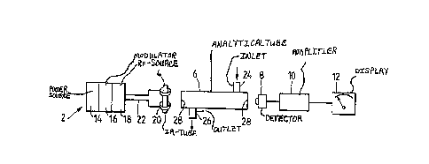
A basic embodiment of the IR-gas analyzer according to the
invention is illustrated in Fig. 3. There is seen the driver 2, which
comprises a power source 14, a modulator 16 which serves as an
electronic "chopper" producing, e.g., a square-wave like pulse of
selectable duty cycle and rate, and an oscillator 18 acting as an RF
source. The IR-tube 4 is capacitatively coupled to the RF-source 18
by means of metal rings 20 which serve a capacitor plates, and a
coaxial cable 22. Optical means can be used to direct the radiation
into the analytical cell.
The analytical cell 6 has an inlet 24 and an outlet 26, as well
as two windows 28 which, obviously, must be at least partially
transparent to the specific IR-radiation emitted by the source 4.
20For many applications, however, the gas sample need not be
confined in a cell. With the IR-radiation suitably concentrated or
. .
. .
~ .
~Z77~7
- 13 -
collimated by optical means per se known, measurements can be taken
also in free space over relatively large distances intervening between
the source 4 and the detector 8. It is thus possible to measure or
monitor CO levels in vehicular tunnels, or in chimneys, or the like.
The IR-detector 8 is of the commercially available type, e.g., a
lead selenide detector such as OE-15-54 manufactured by
Optoelectronics. It could also be an Eltec 408 pyroelectric type
detector, or a photoacoustic detector. A detector working on a
different principle consists of a cell having an IR-permeable window
and filled with an IR-absorbing gas which, in dependence of the amount
of radiation absorbed, heats up. temperature variations being measured
with the aid of a thermocouple.
In some cases the detector is arranged to process test and
reference signals in sequence, at different and specific times,
switching over being effected by an "information" link between the
IR-source and the detector.
The output of the detector 8 is processed and amplified in the
amplifier 10 and eventually reaches the display unit 12. The latter
can have many forms, analog or digital, giving the concentration in ~,
ppm, etc. Where absolute values or great accuracy are not required,
concentrations may be indicated by a number of LED's, with more LED's
* Trade Mark
' ~
. ' ~ , ~ , .
7507
- 14 -
lighting up the higher the concentration determined. Other indicating
means may include optical or acoustical or speech warning devices.
Fig, 4 schematically illustrates a further embodiment, in which
use is made of a reference cell 6', filled with a known concentration
of the target gas, say C02 or with a "transparent" solid or gas like
N2, and having its own detector 8'. The outputs from the two detectors
8 and 8' are fed to an electronic unit 30, where they are compared and
the thus processed signal amplified and transmitted to the display
unit 12 and/or to a control unit 13 used for controlling equipment
sucn as blowers, exhausters, humidifiers, etc., to maintain target-gas
concentrations within presettable limits.
Yet another embodiment is illustrated in the schematic drawing of
Fig. 5. A gas analyzer of this type is used for clinical purposes in
the determination of the C02-content of exhalation air. The patient
inhales and exhales through the tubular cell 6 which, during the
inhalation stroke ~, acts as reference cell, passing as it does the
room air with its known C02 content. During the exhalation stroke E,
C2 concentration in the tubular cell 6 - now acting as analytical
cell - increases, causing absorption to increase, and the detector
will consequently receive less radiation. Detector signals after each
stroke are compared in the comparator and amplifier unit 30, and the
exhalation value fed to the display unit 12.
. .
.
~277SC~7
-- 15 --
Fig, 6 represents an IR-source according to the invention. There
is seen the vial 4, the electrodes 20 which in this embodiment consist
of rings of metal foil attached to the vial and connected to the
driver 2 (Fig. l) by means of a coaxial cable 22. While in this
embodiment the vial 4 is capacitively coupled with the RF-source,
inductive coupling is also possible, as has already been mentioned, by
replacing the two electrodes 20 by a wire coil.
Electrical discharge takes place only in the zone 32 delimited by
the electrodes 20, the rest of the vial volume serving as reservoir 34
used to maintain the proper gas composition of the discharge zone 32.
In many applications, the IR-radiation would be emitted in direction
of arrow A. However, by appropriate choice of window material vs.
envelope material, radiation can also be emitted in direction of arrow
B.
Fig. 7 schematically represents another embodiment, in which the
IR-radiation is emitted over a relatively wide front, as indicated by
the arrows. Here, the extent, in depth, of the discharge zone 32 is
defined by the circumferential reach of the electrodes 20. The vial
volume below that reach constitutes the reservoir 34.
Fig. 8 shows an embodiment of the IR-source that simultaneously
emits test as well as reference signals. The vial 4 in this embodiment
is U-shaped, each limb of the U having a set of electrodes 20 and a
. : - .
.. . .
,
.
~;~77~;0'7
- l6 -
window 36. The gas filling of the vial is such as to produce two
different radiations, one of which is the test radiation T which is to
be absorbed by the target gas, the other is the reference radiation R,
which is not absorbed by the gas. Further provided are two filters 38,
40, the first one of which filters out the test radiation T, leaving
only the reference radiation R~ the other one filtering out the
reference radiation R, leaving only the test radiation T. The relative
intensities of T and R are at a known and fixeo ratio that will not
change with time, even if vial output should vary due to aging,
surges, or the like. The vial is connected to a driver which alterna-
tingly excites one pair of electrodes 20 at a time, and so the source
alternatingly emits radiations of different spectral composition from
different portions of the source.
The embodiment shown in Fig. 9 provides a solution to the
problem of molecular gases P which are fragmented in the presence of
energetic electrons such as those prevailing in an electrical
discharge and for which the embodiments discussed so far do not
provide a satisfactory rate of recombination.
As can be seen in Fig. 9, the vial 4 is subdivided by an
IR-transparent partition wall 4 into two chambers, a first chamber 44
and a second chamber 46. Chamber 44 acts like any of the sources
described above which contain an IR-active gas A, and chamber 46
~Z~77~07
- 17 -
contains a mixture of at least the gases A and P in an appropriate
ratio.
Resonant IR-radiation emitted by gas A from chamber 44 into
chamber 46 is absorbed by the gas component A in chamber 46, producing
excited vibrational states of molecules A. By v-v transfer, energy is
transferred from molecules A to molecules P, which now radiate their
specific IR-radiation when decaying to the ground state. This type of
activation is known as optical pumping.
To have an efficient v-v transfer between A and P, A has to be
chosen so as to have a close energy match with the relevant energy
levels of P.
It will be evident to those skilled in the art that the invention
is not limited to the details of the foregoing illustrative embodi-
ments and that the present invention may be embodied in other specific
forms without departing from the spirit or essential attributes
thereof. The present embodiments are therefore to be considered in
all respects as illustrative and not restrictive, the scope of the
invention being indicated by the appended claims rather than by the
foregoing description, and all changes which come within the meaning
and range of equivalency of the claims are therefore intended to be
embraced therein.
- . . -
., ,- . . . . .