Note : Les descriptions sont présentées dans la langue officielle dans laquelle elles ont été soumises.
~'~776~3~
The present invention relates to a mounting device for
front members of drawers, comprising ~ holding element fastened
to the front member and a supporting means fastened to the
drawer, said supporting means having ad~ustment means for the
vertical and lateral ad~ustment of the drawer as well as a fixed
fastening element and an adjustably mounted supporting element
carrying the holding element.
It is the function of a mounting device for front
members of the above-mentioned kind to hold the front member
:LU adjustably at the drawer so that, when the piece of furlliture i~
assembled, the position of the front member can be ad~usted in
such a manner that all drawer have equal ~oints. Furthermore,
the mounting d~vice for the front member should allow quick
secure mounting of the front member at the drawer.
1~
The present invention improves a mounting d~vice for
front members of the afore-mentioned kind. The mounting device
for front members according to the present invent1on in
particular allow an easy ad~ustment of the front member in the
~ 2U direction of the side and of the height of the piece of
- furniture.
; According to the present invention there is provided a
device for mounting a front panel of a drawer, said devic~
2~ comprising: a holdlng element fastenable to the front panel; a
fastenlng element to be fixed to a side wall of the drawer a hook
member extendiny substantially perpendicular to the front panel
and having a first end includlng means for engaglng sald holding
element; means for mounting a second end of said hook member for
pivotal movement about an axis extending substantially
horizontally and parallel to the front panel, and for selectively
shifting sald hook member and said holding e:lement relative to
said fastening element in a direction perpendicularly of the
front panel, thereby clamping the front panel in a mounted
position, means, operable between said fastening element and said
3~
, .
.
~' ~,..................................... .
~''
'' '
'
7~9~3
hook member, for selectively moving said hook member and sald
holding element laterally relative to said fastening element, and
thereby for adjusting the relative horizontal position of the
front panel with respect to the drawer; and means, operable
between said fastening element and said hook member, for
selectively pivoting said hook member and said holding member
about said axis relative -to aid fastening element, and thereby
for ad~usting the relative vertical position of the front panel
with respect to th~ dra~er.
Thus according to the inventlon the supporting element
L~ into which the holdlng element is
1~;
2~
3U
3~
- la -
.i,~. .. ~ .
'7~
- 2 -
engaged is a hook rotatable about a horizontal axis and
extending vertically to the front member, and a
clamping screw or the like by means of which the.hook
is vertically movable to the front member engaging at
said hook.
. ' .
. .
It is advantageously provided that the hook projects
into a vertical slot in the holding element and engages
therein at a bolt, the hook being snugly received in
the holding element. It is further advantageously
provided that a side adjustment screw which is hori-
~- zontally and parallel aligned to the front member
engages at the hook and abuts at the fastening element.
,
~ :~ This embodiment allows a simple.lateral adjustment of
.,
~ the front member.
:
. 15 The complete mounting device for the front member is
. . .
~ advantageously arranged between double walls, the
~ .
nner wall having perforations which allow access of
adjustment tools to the mounting device.for the front
member.
When the walls are made of metal, the.supporting element
is advantageously held at the walls by means of point
; welding.
.
, To improve the fit of the mounted front member at the
mounting device, a preferred embodiment provides that
'
' ~ :
'~ :
,
` ' '
7~
-- 3
that the hook has an undercut in the region of the bolt.
A further embodiment provides an exxentric mounted in
the hook and abutting at a horizontal flange of the
fastening element. Said eccentric serves for the
vertical adjustment of the hook and, hence, of the ~ront
member and is advantageously arranged between the side
adjustment, screw and the clamping screw.,
Clamping of the hook and, hence, of the front member is
advantageously achieved in that the clamping screw,
which is mounted in a female thread of the hook, has
a countersunk head which rests with one side against
the rim of a hole in the fastening element, said
fastening element having flaps which are bent
advantageously parallel to the front member and at
which the holding element abuts.
BRIEF DESCRIPTION OF THE FIGURES OF THE DRAWING
BeIow an embodiment of the invention will be described
in more detail with reference to the figures of the
drawing in which
Figure 1 shows a schematic side view of the mounting
device for front members according to the invention
Figure 2 shows a top view of a mounting device for front
members according to the invention, parts thereof in
section,
~igure 3 shows a side view of the holding element,
7~9~3
Figure 4 shows a top view of the holding element, and
Figure 5 shows a side view of the hook.
DESCRIPTION OF THE PREFERRED EMBODIMENT
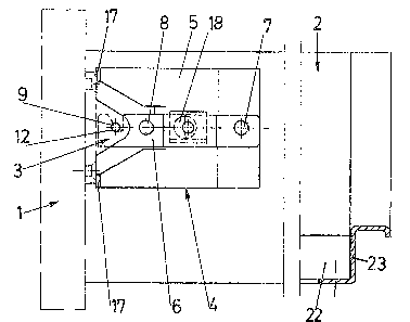
In the figures of the drawing reference number 1 shows
the front member, and reference number 2 shows the
double side wall.
The essential parts of the mounting device for the front
member are the holding element 3 fastened to the front
member 1 and the supporting means 4 fastened to the
drawer side wall 2.
The hook 6 is held at the fas-tening element 5 by means
of the clamping screw 7 and the side adjustment screw 8.
At the holding element 3, the hook 6 is engaged in a
bolt 9. As can be seen from Figs. 3 and 4, the holding
element 3 is symmetrical and comprises two cheeks 10
with a slot 11 being fromed therebetween into which the
hook 6 is inserted in the mounted position. The hook 6
is snugly received in the holding element 3 so that
the hook 6, if laterally displaced or bent, takes along
the holding element 3 and, hence, the front member 1.
In the region of bolt 9, the hook 6 is provided with an
undercut 12 which prevents the front member 1 from
disengaging unintentionally.
,t~769~
At the top and at the bottom the holding element 3 is
provided with inserting surfaces 13, which are triangu-
lar when viewed from the top and facilitate insertion
of the hook 6 into the holding element 3. ~ ;
The clamping screw 7 is provided at the other end of the
hook 6. Said clamping screw 7 is mounted in a ~emale
thread in the hook 6 and has a countersunk head 14. Said
head 14 projects into an oblong hole 15 in the fastening
element 5 and rests against 16 at the rim of said oblong
hole 15.
When the clamping screw 14 is fastened, the countersunk
~ : head 14 presses the hook in the.direction of arrow S of
:~ Fig. 2, and the holding element 3 engaged in the hook 6
is pressed against flaps 17 of the fastening element 5.
15~ A clamping arrangement of the parts is thus obtained
and an absolutely secure anchoring of the front member 1
to the drawer side wall 2 is guaranteed.
An eccentric 18 which rests against a horizontal flange
19 of the fastening element is mounted in the hook 6
between the clamping screw 7 and the side.adjustment
: screw 8. Turning of the eccentric 18 effects pivotal
movement of the.hook 6 about its bearing at the clamping
screw 7.
.
The side adjustment screw 8 is engaged behind a
7'76!3~3
projection 20 of the fastening element. There is to be
mentioned that the side adjustment screw 8 is only
provided at the mounting device for the front member at
one side of the drawer. At the other side of the front
member 1 the hook 6 yields resiliently , when lateral
adjustment is effected.
The internal wall 2' of the side wall is, as already
mentioned, provided with perforations 21 which allow
access of an adjustment tool, for example of a screw
driver, to the mounting device for the front member.
The mounting device for the front member according to
the invention first allows rapid fastening of the front
member 1 and adJustment thereof, and second dismounting
o~ the front member 1 f'rom the drawer side walls 2 at
any time.
At the right of Fig. 1, the drawer side wall 2 is turned
by 90 and a shelf 22 as wel] as a pull~out rail 23 are
illustrated.