Note : Les descriptions sont présentées dans la langue officielle dans laquelle elles ont été soumises.
~ 27~4~
CRYOGENIC REFRIGERATION SYSTEM
This invention relates to a refrigeration
system for vehicles, and more particularly to the
construction of storage compartments for utilizing
carbon dioxide as a refrigerant in transporting products
by vehicles such as trucks, trailers, rail cars and the
like.
Some mechanical systems utilizing expanded
carbon dioxide gas as the refrigerant have been proposed
heretofore. One such system is disclosed in Rubin U.S.
Patent No. 3,561,266 issued February 9, 1971. In the
Rubin patent, carbon dioxide gas was expanded within
containers at the top of the vehicle storage area so as
to form a deposit of snow within the containers. The
snow provided a cold surface on the bottom of the
containers to cool the circulating air within the
vehicle. In addition, in one embodiment a single vent
was provided in each container to permit carbon dioxide
gas to flow into the storage area. In another <
embodiment, the carbon dioxide gas was vented to the
atmosphere outside of the container.
In U.S. Patent 4,502,293, issued March 5, 1985,
to Paul R. Franklin Jr., a carbon dioxide cooling
system is shown wherein carbon dioxide snow is deposited
within a compartment positioned at one end of the
vehicle and within a passageway positioned just beneath
~ 27 ~
the top wall of the vehicle. Fans are provided to draw
air around the containers in the end compartment and
throuqh the passageway over the carbon dioxide snow so
that the cooled air would circ~late through the vehicle
and maintain the contents at the desired cold
temperature.
Other patents disclosing the use of carbon
dioxide either in the form of blocks or snow within
containers which are not open to the vehicle include:
U.S. Patents 1,975,177, the Sherrick; 2,325,371, Clerc;
1,731,807, Allyne; 3,783,633, Glynn et.al; 4,248,060,
Franklin, Jr.; 4,299,429, Franklin, Jr.; 4,376,511,
Franklin, Jr.; 4,381,649, Franklin, Jr.; and 4,404,818,
Franklin, Jr.
The American Frozen Food Institute conducted a
study program trying to develop a suitable cyrogenic
system for shipping frozen foods in rail cars. In a
Executive Summary Report dated March 1985, one prototype
railcar is described wherein liquid carbon dioxide is
stored in a series of elongated tanks spaced lengthwise
to the car beneath an aluminum floor. The liquid carbon
dioxide was vented onto the top of the load to form a
blanket of carbon dioxide snow on the top and around the
load. The blanket was rebuilt as necessary during
shipment.
Because of the direct contact of the snow with
the load, the products in some parts of the load were
reduced to below minus ninety degrees F. At such a low
~ Z77~4~
temperature, some products became very brittle and
broke. Also, because the loads are giving off moisture
the direct exposure of the snow making nozzles to the
moisture caused them frequently to freeze closed. And
the weight of the carbon dioxide tanks took away usable
payload.
Fink et al, U.S. Patent 4,593,536, represents a
further development of the American Frozen Food
Institute program. Therein a rail car is illustrated
wherein carbon dioxide snow is deposited in a bunker at
the roof of the car. Vents are provided along one
sidewall for the escape of carbon dioxide so that it can
flow downwardly along such side wall, throuqh lateral
passageways beneath the floor, and thence upwardly along
the opposite sidewall and back across the load, all by
convection. ~owever, in practice the cold carbon
dioxide gas did not effectively flow upwardly along the
opposite side wall and the product adjacent such wall in
a car so designed would get undesireably warm,
particularly in warm weather.
It is an object of the present invention to
provide an improved shipping container for frozen food
utilizing liquid carbon dioxide as the refrigerant.
More particularly it is an object of the
invention to provide a rail car construction utilizing
carbon dioxide snow as the refrigerant wherein all the
contents of the car will be maintained within desireable
temperature limits during shipment.
1~7~ 4 ~
In accordance with the illustrated embodiment a
railcar heavily insulated on all sides is provided with
a lengthwise compartment at its top in which a deposit
of carbon dioxide snow may be ~ormed. The bottom of the
compartment is provided with openings along each side
and end wall of the car through which sublimating carbon
dioxide gas may escape. Each of the walls is formed
with sinuous channels to permit flow of the carbon
dioxide gas towards the floor along the surface of the
adjacent load. The floor of the car is formed with open
top lengthwise channels to receive the carbon dioxide
gas and to conduct it in contact with the lower surface
of the load to one end of the car whereat a discharge
manifold collects the gas for discharge through the
adjacent end wall of the car. with such construction,
product within the car will be maintained within desired
temperature limits throughout transit.
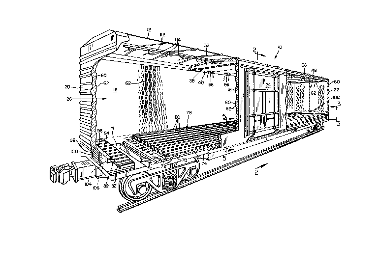
Fig. 1 is a perspective view partly broken away
of a refrigerated rail car incorporating the present
invention.
Fig. 2 is an enlarged cross-sectional view of
the rail car of Fig. 1 taken generally along line 2-2.
Fig. 3 is an enlarged, fragmentary
cross-sectional view of the rail car looking in the
direction of the arrows 3-~ of Fig. 1.
Fig. 4 is a fragmentary cross-sectional view of
the rail car taken generally along line 4-4 of Fig. 3.
Fig. 5 is a fragmentary sectional view taken
1277~34 ~
along line 5-5 of Fig. 1.
Fig. 6 is an enlarged fragmentary view of the
end of a snow making nozzle.
Fig. 7 is a view of t~e inlet plumbing.
Illustrated at 10 is a rail car constructed in
accordance with the present invention. While the
invention is illustrated in connection with a rail car,
it will be apparent that the invention could be
incorporated in other types of vehicles such as trucks
or trailers.
The rail car 10 is provided with a conventional
exterior roof 12, a floor 14, and opposite side walls
16, 18 extending between end walls 20, 22. Each of the
side walls 16, 18 is preferably provided with sliding
doors, only the door 24 in sidewall 18 being
illustrated, and which doors are preferably heavily
gasketed (not shown) to minimize leakage of air into or
refrigerant out of the interior of the rail car. The
foregoing elements define, of course, a storage area 26,
in which the product to be transported is positioned.
Referring first to the top of the rail car,
means are provided for maintaining above the storage
area 26 a deposit of carbon dioxide snow as a
refrigerant source for the load contained within the
storage area. Referring more particularly to Figures 1
and 2, the car 10 is formed with a compartment 32 at the
top for retaining a supply of carbon dioxide snow. The
compartment 32 has a top wall 34 formed of fiberglass or
1277E3d~ ~
other suitable material extending substantially parallel
to the roof 12. The wall 34 is spaced from the roof 12
by any suitable support and in which space is provided a
layer of suitable foam insulation 36. The bottom wall
38 of the compartment 32 is defined by a pair of
horizontally spaced panels 40, 42, which extend from one
side of the car to the other and between which is
positioned a further layer of foam insulation 44. As
shown in Figure 2, the panel 34 defining the top wall of
the compartment curves down at its opposite sides
adjacent stringers 46, 48 which extend the length of the
car. The opposite ends of the wall 34 are secured to
the adjacent stringer so that the wall is supported
there~y. Secured to the stringers 46, 48, respectively,
are a pair of L shaped brackets 50, 52, over which the
bottom compartment wall 38 extends and is supported
thereby. The stringers 46, 48 are suitably supported by
means not shown from the frame of the car 10. As will
be apparent the wall 38 also defines a ceiling for the
storage area 26.
The side walls and end walls of the car 10 are
likewise heavily insulated with a layer of foam
insulation 60. A liner 62 is provided on each of the
side walls 16, 18 and end walls 20, 22 on the inner side
of the insulation and which liner is preferably formed
of sinusoidal f iberglass sheets backed by plywood. Such
panels are shown in U.S. Patent 3,206,946, Lindersmith,
et al. The liners 62 are supported from the f rame of
l2rl~4.~
the rail car by conventional Nelson studs (not
illustrated), or other suitable means. The liners 62
define downwardly directed sinusoidal channels from
ceiling to floor as best shown-in Figure 1. The bottom
wall 40 of the compartment 32 is provided with a
plurality of openings 66 along each of the side walls
16, 18 and alonq each end wall 20,22 of the car and
which openings are preferably slanted toward the
adjacent wall. These openings are provided for the flow
of carbon dioxide gas sublimating from the snow
contained within the compartment 32 and which gas may
then flow downwardly along the adjacent wall through the
sinusoidal passageways defined thereby. The openings on
opposite walls preferably are offset with respect to
each other.
The floor of the car 10, over a conventional
decking layer 70, is provided with a plurality of
transverse stringers 72, between which is disposed a
layer 74 of foam insulation. Supported on and extending
over the transverse stringers 72 is a load supported
decking 78 which comprises a plurality of longitudinally
extending elements 80 defining channels 82 extending
longitudinally substantially the length of the car.
Preferably the decking 78 is that sold under the
trademark "All - Air" and conventionally utilized for
flooring in trucks and other refrigerated containers.
Such deckinq comprises a base plate 84 from which the
floor elements 80 extend upwardly. Except for the
~277~4~`~
floor elements 80' adjacent the side walls 16 and 18 the
elements 80 are T-shaped. However, the floor elements
80' next adjacent the sidewalls as best shown in Fig. 5,
are simply an upstanding flange so as to provide an
unobstructed opening into a channel 82' defined by the
element 80' and the adjacent element 80. Thus carbon
dioxide gas flowing down a side wall 16, 18 may flow
freely into the adjacent channel 82'.
The floor elements 80, 80', terminate short of
the end wall 22 so as to provide a plenum 86 between the
liner 62 of the end wall 22 and the ends of the floor
elements, the purpose of which will be made apparent
hereinafter. A perforated plate 92 preferably extends
across the width of the car between the sidewalls 16, 18
between the ends of floor elements 80, 80' and the
adjacent liner 62 of wall 22, see Fig 3.
Adjacent to the opposite end 20 of the car, a
collecting manifold 94 is provided and which is arranged
to open into all of the channels 82 but excluding the
sidemost channels 82'. The manifold 94 is arranged to
exhaust carbon dioxide gas to the outside through an
opening 96 positioned in the end wall 20 directly
opposite the manifold. A duct 98 connects the manifold
to the opening. Downwardly slanted fixed louvers 100
preferably are positioned in the opening to provide
protection from rain or the like. In addition an
automatic back draft shutter is preferably provided in
the duct 98 to permit flow through the duct only when
1277~34~
the pressure inside the car 10 is greater than that of
the surrounding atmosphere. Such shut'ter preferably
comprises a plurality of free swinging horizontally
hinged vanes 104 having weatherstrips 106 on each to
provide an effective seal in the closed position thereof.
Means are provided for filling the compartment
32 with carbon dioxide snow. In the illustrated
embodiment a distribution pipe 112 extends from car end
22 substantially the length of the car through the top
insulation 36. Extending downwardly from the
distribution pipe 112 into the compartment 32 arè a
plurality of distribution nozzles 114. Each of the
nozzles 114 consists of a pipe closed at its bottom end
but provided with two diametrically opposite apertures
116 above the closed end which have the dual purpose of
permitting carbon dioxide liquid to spray outwardly and
form a snow as the compartment is filled and also of
draining any liquid carbon dioxide from the nozzle after
filling of the compartment has been completed so that
the nozzle remains free and open in the event that
additional snow has to be formed within the compartment
during a shipment.
The distribution pipe 112 is connected to a
downwardly extending filler pipe 118 that is connected
to a filling assembly 108 which in turn is duplicated on
opposite sides of the car so the assembly can be
connected to a source of liquid carbon dioxide at either
side of the railroad track. The filling assembly
g
i~7~34~
comprises on each side a quick connect adapter 122 for
connection to a liquid carbon dioxide source, a strainer
124, a drain line 126, a pressure relief safety valve
128, and a shut off valve 130.-
Suitable temperature sensors can be provided atdesired locations within the car and connected to a
temperature gauge 130 or gauges which may be located at
the end 22 or at some other convenient location on the
exterior of the car.
Preferably the foam insulation in the ceiling,
floor and walls is formed in place in conventional
manner after the linings, floor structure, etc. is in
place so as to fill as nearly possible all the space
where insulation is desired.
When the car is to be utilized for the
transport of frozen foods, the compartment 32 is charged
with carbon dioxide snow and the car permitted to stand
until the temperature has been sufficiently reduced for
loading. As the carbon dioxide snow within the
compartment 32 sublimates, the cold carbon dioxide gas
will discharge through the gas ducts 66 in the bottom
wall 40 of the compartment and will flow downwardly
along the sides of the car and primarily into the
sidemost channels 82'. If the car is not loaded, some
of the carbon dioxide gas will, of course, spill across
the top of the side most floor elements 80' and into the
-- 10 --
34~
inner channels 82. The gas will flow towards the
discharge manifold 94 and exhaust through the exit
opening 96.
When the temperature bas been lowered
sufficiently, the car doors can be opened and the car
loaded with the frozen product that is to be shipped.
Usually the load will be compacted snugly positioning
product adjacent to the liners 62 of the side walls 16,
18 and the end walls 20, 22. When the car is fully
loaded, the doors will again be closed and the
compartment 32 fully charged with carbon dioxide snow.
A 60 foot car, for example, will accept-a charge of
about 12 tons of carbon dioxide and with five inches of
urethane foam insulation on the outer walls such a
charge is sufficient to maintain temperatures of zero
degrees Fahrenheit or below for a period of twelve days
during summertime conditions.
When loaded, the carbon dioxide sublimating
from the snow will escape through the gas discharge
openings 66 and will flow downwardly along the sides and
the ends of the car through the sinusoidal channels
defined by the liners 62 and the adjacent load. The gas
flowing down the sides 16, 18 will flow into the side
channels 82' and thence will flow towards the end 22 of
the car, and into the plenum 86, thence into the center
channels 82 through which the cold carbon dioxide will
flow towards the opposite car end 20 and into the
collecting manifold 94. The carbon dioxide flowing down
1~77~34~-~
the end wall 22 will flow through plate 92 into the
plenum 86 and thence into the inner channels 82 while
the gas flowing down the end wall 20 will flow directly
into the collecting manifold 94. Flow of the cold
carbon dixoide gas through the channels 82, 82' is
desired, of course, so as to provide a refrigerating
layer beneath the load that is supported on the floor
elements 80. Some of the carbon dioxide gas will, of
course, seep through the cracks and crevices of the
load and directly into the channels 82 and thence to the
manifold 94. As the carbon dioxide warms and pressure
within the car increases some of the gas will escape
through the opening 96.
Because the carbon dioxide snow is not
deposited directly upon the load but is maintained in
the compartment 32, which is insulated from the top of
the load by the bottom compartment wall 38, the product
shipped within the car will not be reduced to an
unacceptable temperature to impair its durability.
Moreover, because the cold carbon dioxide gas is flowing
downwardly on each of the opposite sides and on the ends
of the car and in direct contact with the bottom of the
load, all parts of the load will be maintained at a
desirably low temperature to preserve the quality of the
product shipment.
Obviously, if the duration of the shipment is
such that the snow begins to exhaust and the temperature
within the car begins to rise towards unacceptable
- 12 -
~27~4~
levels, the compartment 32 can easily be recharged with
a supplemental supply of carbon dioxide snow so that the
desired temperature are maintained until the car is
unloaded.
Having illustrated and described the preferred
embodiment of the present invention, the scope of the
present invention should be determined by the following
claims.