Sélection de la langue

Search

Sommaire du brevet 1278484 

Énoncé de désistement de responsabilité concernant l'information provenant de tiers

Une partie des informations de ce site Web a été fournie par des sources externes. Le gouvernement du Canada n'assume aucune responsabilité concernant la précision, l'actualité ou la fiabilité des informations fournies par les sources externes. Les utilisateurs qui désirent employer cette information devraient consulter directement la source des informations. Le contenu fourni par les sources externes n'est pas assujetti aux exigences sur les langues officielles, la protection des renseignements personnels et l'accessibilité.

Disponibilité de l'Abrégé et des Revendications

L'apparition de différences dans le texte et l'image des Revendications et de l'Abrégé dépend du moment auquel le document est publié. Les textes des Revendications et de l'Abrégé sont affichés :

  • lorsque la demande peut être examinée par le public;
  • lorsque le brevet est émis (délivrance).
(12) Brevet: (11) CA 1278484
(21) Numéro de la demande: 1278484
(54) Titre français: APPAREIL D'OSTOMIE
(54) Titre anglais: OSTOMY APPLIANCE
Statut: Durée expirée - après l'octroi
Données bibliographiques
(51) Classification internationale des brevets (CIB):
  • A61F 05/448 (2006.01)
(72) Inventeurs :
  • STEER, PETER LESLIE (Royaume-Uni)
(73) Titulaires :
  • E.R. SQUIBB & SONS, INC.
(71) Demandeurs :
  • E.R. SQUIBB & SONS, INC. (Etats-Unis d'Amérique)
(74) Agent: OSLER, HOSKIN & HARCOURT LLP
(74) Co-agent:
(45) Délivré: 1991-01-02
(22) Date de dépôt: 1986-12-05
Licence disponible: S.O.
Cédé au domaine public: S.O.
(25) Langue des documents déposés: Anglais

Traité de coopération en matière de brevets (PCT): Non

(30) Données de priorité de la demande:
Numéro de la demande Pays / territoire Date
8530369 (Royaume-Uni) 1985-12-10

Abrégés

Abrégé anglais


ABSTRACT
OSTOMY APPLIANCE
An ostomy appliance intended for attachment
to a peristomal area of a wearer includes a pad of
medical-grade skin-attachable adhesive material, a
first coupling element secured thereto, the element
having a medically-extending flange attached to a
surface of the pad and an upstanding rib of closed
loop form constructed to couple with a counterpart
(second) coupling element on a bag or pouch. An
inner chute member is located radially within and
adjacent to the first coupling element, the chute
member having a substantially cylindrical wall
covering the whole of the radially inner surface of
the first coupling element. At one of its ends,
the chute has a radially outwardly extending flange
positioned so that it traps the chute member in
position when the two coupling elements are coupled
together.

Revendications

Note : Les revendications sont présentées dans la langue officielle dans laquelle elles ont été soumises.


- 5 -
The embodiments of the invention in which an
exclusive property or privilege is claimed are defined as
follows:
1. An ostomy appliance intended for attachment
to a peristomal area of a wearer including a pad of
medical-grade skin-attachable adhesive material, a first
coupling element secured thereto, the element having a
medically-extending flange attached to a surface of the
pad and an upstanding rib of closed loop form constructed
to couple with a counterpart second coupling element on a
bag or pouch having a stomal orifice; said second
coupling element comprising inner and outer parallel and
upstanding spaced apart walls which form a channel
surrounding the stomal orifice to accept the upstanding
rib of the first coupling element, and a separate inner
chute member located radially within and adjacent to the
first coupling element, the chute member having a
substantially cylindrical wall covering the whole of the
radially inner surface of the first coupling element and,
at one of its ends, a radially outwardly extending flange
positioned so that it traps the chute member in position
when the two coupling elements are coupled together.

Description

Note : Les descriptions sont présentées dans la langue officielle dans laquelle elles ont été soumises.

r~
~.~7~ L XF 5 3
OSTOMY APPLIANCE
This invention relates to a body-side ostomy
appliance, for attachment to the peristomal area
of a wearer, to permit removable attachment of a
bag or pouch thereto.
Ostomy appliances are known in which a
coupling element on the bag is engaged with one on
an adhesive pad, the latter being stuck onto the
wearer. One successful design is that shown in
United States Patent No. 4,460,363.
It is an aim of the invention to provide a
design of ostomy appliance in which the chance of
lodgment of faecal material in crevices of the
appliance is greatly reduced, if, indeed, it is not
wholly avoided.
According to the invention, an ostomy
appliance intended for attachment to a peristomal
area of a wearer includes a pad of medical-grade
skin-attachable adhesive material, a first coupling
element secured thereto, the element havlng a
medically-extending flange attached to a surface of
the pad and an upstanding rib of closed loop form
constructed to couple with a counterpart (second)
coupling element on a bag or pouch, and an inner
, . . ., ~,. ~. ;, ~ -

7~
X~53
--2--
chute member located radially within and adjacent
to the first coupling element, the chute member
having a substantially cylindrical wall covering
the whole of the radially inner surface of the
first coupling element and, at one of its ends, a
radially outwardly extending lip positioned so that
it traps the chute member in position when the two
coupling elements are coupled together.
The present invention is applicable, with
minor obvious modifications, to a variety of ostomy
appliances, in particular those having a pair of
interchangeable coupling elements, one on each of
the pad and the pouch.
In a preferred version of the invention, a
first coupling element has a rib and the second
coupling element has a channel surrounding the
stomal orifice, and the flange of the chute member
is positioned to engage under the end of the
radially inner channel wall.
The invention will be better understood from
the following non-limiting description of an
example thereof given with reference to the
accompanying drawings.
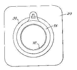
Figure 1 is a front elevation view, omitting
the bag or pouch, of two coupling elements together
and including a chute member; and
Figure 2 is a vertical axial cross section,
with the bag or pouch indicated diagramatically,
through an assembled ostomy appliance showing two
coupling elements and a chute member.

~Z78~
XF53
The illustrated ostomy appliance according
to the invention ls intended for attachment to a
peristomal area of a wearer and includes a pad 20
of medical grade skin-attachable adhesive material,
a first coupling element 22, and a chute member 24.
The pad 20 is substantially rectangular in form and
may have on its rear surface 26 a stripable
protective layer. As shown in Figure 2, a central
stomal orifice 28 has been cut therein, but as sold
to the purchaser, the pad may constitute a
substantlally continuous rectangular patch.
The coupling element 22 comprises a radially
outwardly extending flange 30 and a rib member 32
extending therefrom to encircle the stomal orifice.
The rib 32 has a rim 34 thereon and an integral
deflectable sealing strip 36. For a fuller
description of the manner of operation of these
parts attention is directed to the disclosure of
United States patent 4,460,363.
The first coupling element 22 is intended to
cooperate with a second coupling element 56. This
is of channel form and is annular also surrounding
the stomal orifice. The second coupling element 56
has an inner wall 50, an outer wall 52 and a
channel base 54. The axis of the ostomy appliance
is indicated at 62. A pouch or bag is
diagramatically indicated at 64. The bag wall 66
has a stomal aperture therein, and the wall 66 is
secured to the second coupling element 56 in any
suitable manner, for example by a a plastics weld
seam indicated at 68.
In accordance with the present invention, a
chute member 24 is provided to guard against the

~2~34i!~L
XF53
possibility of faecal material becoming trapped in
parts of the coupling. The preferred chute member
24 has a flange portion 70 which extends radially
outwardly and underlies the assembled coupling
elements 22 and 56 and the flange 70 is integral
with a cylindrical tube or sleeve portion 72 which
is located within and close to the inner wall 50 of
the second coupling element 56. As can be seen
best from Figure 2, presence of the chute member 24
wholly prevents or greatly minimizes the chance of
any faecal material becoming lodged in the parts of
the coupling and the crevices and recesses
necessarily defined thereby~

Dessin représentatif
Une figure unique qui représente un dessin illustrant l'invention.
États administratifs

2024-08-01 : Dans le cadre de la transition vers les Brevets de nouvelle génération (BNG), la base de données sur les brevets canadiens (BDBC) contient désormais un Historique d'événement plus détaillé, qui reproduit le Journal des événements de notre nouvelle solution interne.

Veuillez noter que les événements débutant par « Inactive : » se réfèrent à des événements qui ne sont plus utilisés dans notre nouvelle solution interne.

Pour une meilleure compréhension de l'état de la demande ou brevet qui figure sur cette page, la rubrique Mise en garde , et les descriptions de Brevet , Historique d'événement , Taxes périodiques et Historique des paiements devraient être consultées.

Historique d'événement

Description Date
Inactive : Périmé (brevet sous l'ancienne loi) date de péremption possible la plus tardive 2008-01-02
Inactive : TME en retard traitée 2003-12-17
Accordé par délivrance 1991-01-02

Historique d'abandonnement

Il n'y a pas d'historique d'abandonnement

Titulaires au dossier

Les titulaires actuels et antérieures au dossier sont affichés en ordre alphabétique.

Titulaires actuels au dossier
E.R. SQUIBB & SONS, INC.
Titulaires antérieures au dossier
PETER LESLIE STEER
Les propriétaires antérieurs qui ne figurent pas dans la liste des « Propriétaires au dossier » apparaîtront dans d'autres documents au dossier.
Documents

Pour visionner les fichiers sélectionnés, entrer le code reCAPTCHA :


Pour visualiser une image, cliquer sur un lien dans la colonne description du document. Pour télécharger l'image (les images), cliquer l'une ou plusieurs cases à cocher dans la première colonne et ensuite cliquer sur le bouton "Télécharger sélection en format PDF (archive Zip)" ou le bouton "Télécharger sélection (en un fichier PDF fusionné)".

Liste des documents de brevet publiés et non publiés sur la BDBC .

Si vous avez des difficultés à accéder au contenu, veuillez communiquer avec le Centre de services à la clientèle au 1-866-997-1936, ou envoyer un courriel au Centre de service à la clientèle de l'OPIC.


Description du
Document 
Date
(aaaa-mm-jj) 
Nombre de pages   Taille de l'image (Ko) 
Revendications 1993-10-14 1 27
Abrégé 1993-10-14 1 20
Dessins 1993-10-14 1 19
Description 1993-10-14 4 103
Dessin représentatif 2001-09-04 1 7
Taxes 1996-12-18 1 81
Taxes 1995-12-18 1 69
Taxes 1994-12-18 1 69
Taxes 1993-11-04 1 59
Taxes 1992-12-08 1 26