Note : Les descriptions sont présentées dans la langue officielle dans laquelle elles ont été soumises.
12792~0
1 BALL CHECK VALVE
Background of the Invention
1. Field of the-Invention
-
This invention relates to a check valve
assembly wherein a ball is movable along a curved
path of travel between a first, flow impeding
position adjacent a fluid inlet and a second, flow
enabling position spaced from the inlet, and
wherein the second position i~ disposed laterally
of a substantially straight fluid passageway
between the fluid inlet and a fluid outlet. A
housing for the assembly includes two opposed,
spaced members for guiding the ball between the
first position and the second position, and the
configuration of the members as well as the hous-
ing walls is such that the ball is continuously
cleansed of solid matter by fluid flow around the
ball when the latter is in its second, flow enab-
ling position.
2. Description of the Prior Art
A variety of check valves have been
proposed in the past for permitting the flow of
fluids through a conduit in a first direction,
while substantially precluding flow of fluids
through the same conduit in an opposite direction.
Some check valves are of a "flapper" type and have
a hinged valve plug or panel which is shiftable
toward a fluid inlet for ob~tructing flow in one
direction, and which is swingable to an open
position spaced from the inlet for permitting flow
in the opposite direction. It has been found,
however, that flapper valves are not entirely
satisfactory for certain applications, including
instances where.the flowing fluid carries solid
(Docket No. 18975)
12~79Z;~O
1 matter or debris which can become entangled with
the valve hinge or otherwise impede smooth, free
action of the hinge such that the valve does not
open and close within desired specificàtions.
Other types of check valve assemblies
utilize a ball which is shiftable within a chamber
of a housing between a flow impeding position
adjacent a fluid inlet and a flow enabling posi-
tion spaced from the fluid inlet. The ball has a
diametric cross section larger than the diameter
of the fluid inlet, and the housing is provided
with a spherical seat for the ball adjacent the
fluid inlet so that the ball and seat form a fluid
resistant seal to substantially prevent fluid flow
in an opposite direction from the chamber and back
through the inlet.
Certain types of ball check valves have
housings with an internal fluid chamber of a
generally "Y" configuration. In these valves, the
fluid inlet is located adjacent the juncture of
two diverging passageways, and one of the passage-
ways functions as a guiding channel for movement
of the ball while the other passageway has a fluid
outlet at its outermost end and serves as a fluid
conduit between the inlet and outlet. Unfortu-
nately, fluid captured in the channel for the ball
is stagnant, which facilitates the collection of
solid debris and other foreign matter occasionally
to such a degree thst the valve is rendered in-
operable.
Another type of ball check valve assem-
bly is shown in U.S. Patent No. 3,741,243 to
Deibler et al., which is assigned to the assignee
of the present invention. The check valve assem-
bly of this patent has 8 ball contained within a
1279230
1 housing chamber and movable in approximately a
straight line between a position adjacent the
fluid inlet and a position intermediate the inlet
and an outlet port. The chamber includes a bypass
region of sufficient cross sectional area to
permit fluid flow around the ball when the valve
is in its open position. While the check valve
shown in U.S. Patent No. 3,741,243 represents a
significant advance in the art due to elimination
of stagnant pockets of fluid, this type of valve
can satisfactorily handle fluids carrying solid
matter of limited size, since the fluid flow is
confined to a somewhat restricted pathway past
ball guiding structure and around the surface of
the ball until the fluid outlet is reached.
As can be appreciated, it would be a
desirable advance in the art if a ball check valve
assembly was provided wherein stagnant pockets of
fluid are eliminat~d and the ball is guided away
from a straight fluid passageway betwçen a fluid
inlet and an outlet so that the ball does not
obstruct or otherwise hinder flow of fluids
through the valve assembly. Moreover, the check
valve housing and ball guiding structure should be
configured to eliminate flutter of the ball when
the latter is shifted toward a flow enabling
position, since such flutter could otherwise cause
turbulence in the flow and lead to cavitation.
Summary of the Invention
The present invention overcomes the
above noted disadvantages of prior ball check
valve assemblies by provision of a valve housing
with ball guiding structure that is operable to
shift a ball to a position laterally of a sub-
~279Z30
1 stantially straight fluid passageway between afluid inlet and outlet, so that the fluid encoun-
ters little resistance to flow and relatively
large solid matter carried by the fluid can easily
pass through the valve housing without encounter-
ing obstructions. Stagnant areas of fluid within
the housing are eliminated and a small portion of
the fluid is diverted around the ball for cleans-
ing the latter. The ball is maintained in its
flow enabling position with a minimum of force, so
that ball flutter is substantially eliminated.-
In more detail, the ball guiding struc-
ture of the present invention comprises two op-
posed, spaced members which engage opposite side
regions of the ball and which are configured to
guide the ball along a pathway having a variable
slope. The pathway of the ball approaches a
horizontal axis as the flow enabling position of
the ball is reached, so that a minimum amount of
force is required to retain the ball in its flow
enabling position and, as a result, ball flutter
is substantially reduced or eliminated. However,
the ball guiding members are configured so that
the motion of the ball is not truly horizontal
as the latter reaches its flow enabling position,
so that the ball can quickly return by gravity to
its flow obstructing position adjacent the inlet
whenever the flow rate of fluid through the valve
approaches zero or begins to travel in a reverse
direction through the valve.
The valve housing includes a generally
bell shaped casing having a flared, opened end
section and a fluid inlet opposite the opened end
section. The valve housing also includes a body
which is removab.ly connected to the casing flared
lX792:~0
1 end section for covering the latter, and the body
includes a fluid outlet as well as two outwardly
projecting ball guiding members which matingly fit
within opposed walls of the flared,~opened end
section of the casing. As such, the valve housing
can be easily opened for inspection and mainten-
ance if necessary, and the ball may be readily
removed for replacement.
The body of the valve housing has a stop
which engages the ball when the latter is in its
flow enabling position. The stop is constructed
to contact only a relatively small segment of the
ball, so that a portion of the fluid flowing
through the valve can flow around the ball~and
flush solid matter from the surface of the ball.
The configuration of the valve casing and cover
body is such that stagnant pockets of fluid in the
valve are eliminated whenever fluid is flowing
through the same, so that debris and other solid
matter does not accumulate within the valve during
normal use of the latter.
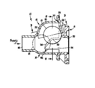
Brief Description of the Drawing
Figure 1 is a side cross sectional view
of the check valve assembly of the present inven-
tion, wherein the assembly includes a housing
- having a casing and a cover body in mating contact
with the casing, and wherein a ball of the valve
assembly is shown in full line to represent its
flow enabling position and in broken line to
depict its flow obstructing position;
Fig. 2 is an end sectional view taken
along line 2-2 of Fig. l;
Fig. 3 is a cross sectional view taken
along line 3-3 of Fig. l; and
~.~792~0
1 Fig. 4 is a view similar to Fig. 1
wherein the ball is intermediate its flow enabling
position and flow obstructing position, and the
arcuate pathway of travel of the bal-l is repre-
sented by a line passing through the center of the
ball.
Detailed Description of the Drawing
A check valve assembly is shown in Figs.
1-4 and is designated broadly by the numeral 10.
In general, the assembly 10 comprises a housing 12
which includes a casing 14 and a cover body 16.
The assembly 10 also includes a spherical ball 18
which optionally can be comprised of a synthetic
rubber material such as neoprene and preferably
has a specific gravity at least ten percent great-
er than the fluid encountered by the assembly 10.
- More specifically, the casing 14 is
generally bell shaped and has walls 20 defining a
chamber 22 which is generally of an oval config-
uration in vertical section, as best illustrated
in Fig. 2. The casing 14 presents a flared, open
end section 24 and an outwardly extending, cylin-
drical fluid inlet 26 (Figs. 1 and 4) in generally
opposed relationship to the flared, open end
section 24.
- The body 16 is removably connected by
fasteners (not shown) to the casing 14 in order to
generally cover the open end section 24 when the
assembly 10 is in use. The fasteners pass through
holes 28 (Fig. 2) provided in the end section 24
to engage surfaces of the body 16, and an 0-ring
30 seated within a groove of the end section 24
provides a seal between the casing 14 and the body
16 to resist the leakage of fluid therebetween.
~2792;~0
1 The body 16 also has an outwardly projecting, sub-
stantially cylindrical fluid outlet 32, so that a
generally straight fluid passageway 34 is provided
in the chamber 22 between the inlet~26 and the
Outlet 32.
The body 16 has ball guiding structures
or members 36, 36 for guiding the ball 18 along a
path of travel between a first, flow impeding
position adiacent the inlet 26 and a second posi-
tion spaced from the inlet 26. The members 36, 36
are each disposed in spaced, opposed relationship
on opposite upright portions of the housing walls
20, and are engageable with opposed side regions
of the ball 18, as best seen in Figs. 2 and 3.~ As
lS shown, the members 36, 36 each have top surfaces38 which are inclined outwardly in opposite direc-
tions. The surfaces 38, 38 are each curved at an
area designated as 40, the latter of which lies at
an upper portion of the members 36, 36.
The path of travel of the center of the
ball 18 as the latter shifts between its first,
flow obstructing position adjacent the inlet 26
and its second, flow enabling position spaced from
the inlet 26 is shown in Fig. 4 by a line desig-
nated 42. The members 36, 36 are spaced a suffi-
cient distance from the fluid inlet 26 such that
- the ball when moving away from the inlet 26 tra-
vels along a short horizontal path before engaging
the members 36, 36 and beginning an upwardly
inclined movement. Thereafter, kinetic pressure
of the fluid flowing through the chamber 22 be-
tween the inlet 26 and toward the outlet 32 exerts
a force on the ball 18 to propel the same upwardly
along an inclined path of travel in engigement
with the surfaces 38, 38. Next, as the bal~ 18
lX'792;~0
1 approaches its second, upwardmost position, the
curved areas 40, 40 on the members 36, 36 respec-
tively shift the inclination of the path of travel
of the ball 18 in such a fashion that the slope of
the path of travel approaches zero. Referring to
Fig. 4, the line 42 representing the path of
travel of the ball 18 includes an upwardmost
curved portion which reflects movement of the ball
18 as the latter engages the curved areas 40, 40.
However, the path of travel of the ball 18 as the
latter approaches its second, upwardmost position
should preferably not have a slope which equals
zero so that the ball 18 quickly returns by gravi-
ty to its flow blocking position adjacent the
fluid inlet 26 whenever flow of fluids through the
chamber 22 is interrupted or is oriented in a
reverse fashion, from the normal outlet 32 of the
assembly 10 and toward the normal fluid inlet 26.
The variable slope of the line 42 repre-
senting the path of travel of the ball 18 enables
the pressure of fluid flowing through the chamber
22 to retain the ball 18 in its upwardmost posi-
tion with a minimum.of expended force. Since the
movement of the ball 18 approaches a horizontal
axis, a large portion of the force exerted by the
weight of the ball 18 is supported by the members
36 and only a relatively small force need be
exerted by the flowing fluid on the ball 18 to
retain the latter in its second position. Conse-
guently, flutter of the ball 18 is substantiallyreduced and in most cases eliminated, thus reduc-
ing fluid turbulence within the chamber 22 which
could otherwise lead to cavitation. Such an
advantage is particularly useful in applications
utilizing low pressure pumps.
lZ792;~0
1 The cover body 16 is provided with an
inclined, curved wall or stop 44 which contacts
the ball 18 when the latter is in its second,
upwardmost position. ~y comparison of Figs. 1 and
3, it will be seen that the stop 44 engages in
point contact only a very relatively small surface
portion of the ball 18. As such, the ball 18 in
its upwardmost position rests in three point
contact against the two surfaces 38, 38 and the
stop 44, while the remaining portions of the
housing 12 are sufficiently spaced from the ball
18 to enable fluid to completely flow around the
remaining portions of the ball 18 and to continu-
ally flush solid matter from the ball 18 whe~ever
fluid flows through the assembly 10. As illus-
trated in Fig. 3, two channels 46, 46 are thus
provided between the stop 44 and the surfaces 38,
38 to enable the flow of fluids completely~around
the remaining areas of the ball 18 and to prevent
the accumulation of stagnant fluid within the
chamber 22.
The substantially straight configuration
of the fluid passageway 34, as best understood by
reference to Figs. 1 and 4, exerts a minimum
amount of pressure drop on the fluid as the latter
flows from the inlet 26, through the chamber 22
and toward the outlet 32. At the same time, the
configuration of the ball guiding members 36 is
such to shift the ball 18 toward a position spaced
laterally from the fluid passageway 34 and the
fluid inlet 26 so that the ball 18 when in its
upwardmost position does not hinder the flow of
fluids through the housing 12. Consequently, the
assembly 10 can easily pass fluids containing
large quantities of solid matter, such as parti-
.
1 279230
1 culates or debris, even when such solid matter is
of a relatively large size.
Advantageously, the cover body 16 can be
readily removed from the casing 14 for inspection
and repair, if necessary, of the assembly 10. The
provision of the outwardly extending members 36,
36 which matingly fit with inner surfaces of the
casing 14, enables the ball 18 to be removed from
the chamber 22 as soon as the casing 14 is sepa-
rated from the body 16.