Sélection de la langue

Search

Sommaire du brevet 1279357 

Énoncé de désistement de responsabilité concernant l'information provenant de tiers

Une partie des informations de ce site Web a été fournie par des sources externes. Le gouvernement du Canada n'assume aucune responsabilité concernant la précision, l'actualité ou la fiabilité des informations fournies par les sources externes. Les utilisateurs qui désirent employer cette information devraient consulter directement la source des informations. Le contenu fourni par les sources externes n'est pas assujetti aux exigences sur les langues officielles, la protection des renseignements personnels et l'accessibilité.

Disponibilité de l'Abrégé et des Revendications

L'apparition de différences dans le texte et l'image des Revendications et de l'Abrégé dépend du moment auquel le document est publié. Les textes des Revendications et de l'Abrégé sont affichés :

  • lorsque la demande peut être examinée par le public;
  • lorsque le brevet est émis (délivrance).
(12) Brevet: (11) CA 1279357
(21) Numéro de la demande: 1279357
(54) Titre français: ENSEMBLE MANCHON ET PIVOT, ET SON EMPLOI
(54) Titre anglais: PIVOT BUSHING ASSEMBLY APPLICATION
Statut: Durée expirée - après l'octroi
Données bibliographiques
(51) Classification internationale des brevets (CIB):
  • F16F 01/38 (2006.01)
  • B60G 07/02 (2006.01)
  • B60G 13/00 (2006.01)
  • B60G 15/02 (2006.01)
  • F16F 07/00 (2006.01)
(72) Inventeurs :
  • KRAJEWSKI, CASIMIR (Etats-Unis d'Amérique)
  • MELVILLE, RANDOLPH I. (Etats-Unis d'Amérique)
  • PORTER, WILLIAM W. (Etats-Unis d'Amérique)
(73) Titulaires :
  • GENERAL MOTORS CORPORATION
(71) Demandeurs :
  • GENERAL MOTORS CORPORATION (Etats-Unis d'Amérique)
(74) Agent: GOWLING WLG (CANADA) LLP
(74) Co-agent:
(45) Délivré: 1991-01-22
(22) Date de dépôt: 1988-03-21
Licence disponible: S.O.
Cédé au domaine public: S.O.
(25) Langue des documents déposés: Anglais

Traité de coopération en matière de brevets (PCT): Non

(30) Données de priorité de la demande:
Numéro de la demande Pays / territoire Date
090,845 (Etats-Unis d'Amérique) 1987-08-31

Abrégés

Abrégé anglais


PIVOT BUSHING ASSEMBLY APPLICATION
Abstract of the Disclosure:
A suspension rubber bushing pivot installation
for automobiles and the like incorporates an upsetting
washer and expedients associated therewith in the
bushing proper which coact under tightening of a
fastener bolt to enhance the rattle-free frictional
engagement of the latter with its supporting chassis
bracket.

Revendications

Note : Les revendications sont présentées dans la langue officielle dans laquelle elles ont été soumises.


The embodiments of the invention in which an
exclusive property or privilege is claimed are defined
as follows:
1. In a pivot bushing installation for
automotive suspension apparatus and the like, including
support means defining a spaced pair of walls of a
material deformable under predetermined stress, the
walls being apertured on a common axis for reception of
a fastener bolt,
the combination comprising, an elastomeric
pivot bushing assembly received between said walls and
including an inner metallic sleeve having its
longitudinal bore aligned on said axis and its end
surfaces adapted each for engagement with a respective
said wall,
centrally apertured upsetting washer means of
a material relatively substantially less deformable
under said stress than said wall material and including
protuberance means adjacent the central aperture
juxtaposed at the exterior of the respective one of
said walls to an end surface of said sleeve,
and threaded bolt and nut fastener means in
the aligned apertures and bore of said walls, said
sleeve and said washer means whereby under thread
tightening of the fastener means said washer means is
operable to deform the portion of said one wall
intervening said protuberance means and said chamfer
means to enhance frictional engagement of said sleeve
between said walls.

2. In a pivot bushing installation for
automotive suspension apparatus and the like, including
support means defining a spaced pair of walls of a
material deformable under predetermined stress, the
walls being apertured on a common axis for reception of
a fastener bolt,
the combination comprising, an elastomeric
pivot bushing assembly received between said walls and
including an inner metallic sleeve having its
longitudinal bore aligned on said axis and its end
surfaces adapted each for engagement with a respective
said wall, an end surface of said sleeve featuring
chamfer means merging with such longitudinal bore,
centrally apertured upsetting washer means of
a material relatively substantially less deformable
under said stress than said wall material and including
an annular protuberance means adjacent the central
aperture juxtaposed to said sleeve chamfer means at the
exterior of the respective one of said walls,
and threaded bolt and nut fastener means in
the aligned apertures and bore of said walls, said
sleeve and said washer means whereby under thread
tightening of the fastener means said washer means is
operable to deform the portion of said one wall
intervening said annular protuberance and said chamfer
means to enhance frictional engagement of said sleeve
between said walls.

Description

Note : Les descriptions sont présentées dans la langue officielle dans laquelle elles ont été soumises.

9~7
G-508 - C-3955
PIVOT BUSHING ASSEMBLY APPLICATION
The present invention deals with rubber
"bushing" pivot assemblies for automotive road-wheel
suspensions and like applications.
Typically, such pivot bushings comprise inner
and outer metallic sleeves with an intervening rubber
or elastomer cylindrical body of substantial thickness
and, with the outer sleeve joined to a movable
suspension member and the inner sleeve to a chassis
support element, the piYot bushing provides a sturdy,
long-life, non-lubricable pivot bearing meeting the
challenges of automotive use. It is desirable in all
instances to prevent relative movement in the joined
parts other than through the flexure of the elastomer
and, to this end, the inner sleeve is usually
frictionally engaged or clamped at its opposite ends
between spaced arms of the chassis support under the
compression of a threaded bolt and nut fastener applied
through aligned apertures of the support arms and the
central through-bore of the inner sleeve.
Whether due to rust-preventing paints, waxes
or like treatment of the chassis support or bushing, or
due to other events, it is sometimes possible that the
clamping compression on the inner sleeve from the mere
tightening of conventional bolt fasteners will be
insufficient for the desired frictional securement
against the relative movement that might be induced in
some high-force conditions in the vehicle.
By the present invention, a generally
conventional pivot bushing is substantially improved to
meet such conditions. ~he improved bushing
incorporates an upsetting washer and associated
; I ~

3~7
expedients in the bushing inner sleeve cooperable with
an otherwise conventional bolt and nut fastener to
employ thread tightening of the latter in a way to
deform, pinch and enhance the clamped engagement of the
chassis support and inner sleeve together against
relative movement under severe conditions.
The foregoing and other objects, features and
advantages of the invention will be readily apparent
from the following specification and from the drawings,
wherein:
Figure 1 is a fragmentary, perspective view of
an automotive suspension assembly including a pivot
bushing installation according to this invention;
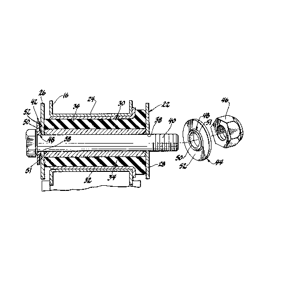
Figure 2 is an enlarged sectional view, partly
exploded, taken generally along the plane indicated by
line 2-2 of Figure 1; and
Figure 3 is an enlarged view of a portion of
Figure 2.
Referring now to Figure 1 of the drawings7 the
sam~ illustrates a conventional automotive suspension
assembly including a wheel carrier 10 rotatably mounted
on a knuckle 12 affixed at its upper regions to a
strut-type telescopic hydraulic damper 14. At its
lower end regions, the knuckle 12 is suitably pivotally
joined with the outboard end of a wishbone-style lower
control arm 16, such lower joint being, for example, a
ball joint 18. The control arm 16 conventionally
requires pivotal mounting of its inboard regions on a
longitudinal axis defined on the vehicle chassis
understructure, such structure being indicated at 20.
Thus, a spaced pair of generally U-section chassis
brackets 22 extend from the understructure 20 generally
.

93~7
aligned on such a longitudinal axis, and the inboard
regions of control arm 16 comprise spaced wishbone legs
which terminate in circular-s~ction apertured bosses 24
each received between the legs of a respective bracket
22 to be pivotally joined thereto.
A pivot bushing installation according to this
invention accomplishes each such joint. Referring to
Figure 2, one joint is illustrated in a partially
complete installation wherein numerals 26 and 28
indicate the laterally spaced pair of flanges or walls
of the bracket 22.
A substantially conventional pivot bushing
assembly 30 is, with its respective lower control arm
boss 24, placed between such walls. The bushing
assembly comprises an outer metallic sleeve 32 press
fitted, spot-welded or otherwise relatively
non-rotatably joined with boss 24, an inner metallic
sleeve 34, and a rubber or other elastomer cylindrical
body or bushing 36 between the two slèeves. As is
conventional, inner sleeve 34 extends in length greater
than the outer sleeve and generally equal the gap
between walls 26 and 28. In this fashion, with a
fastener bolt assembly installed to compress such walls
onto the ends of the inner sleeve, such pressure
typically serves to frictionally prevent relative
motion of the inner sleeve on those walls during
movement of the remainder of the pivot bushing, thereby
to eliminate noise, wear, etc.
In contemplation of the present invention, a
fastener bolt 40 indeed is placed through inner sleeve
34 and through apertures 38 aligned on a common axis of
walls 26, 28. A pair of upsetting washers are placed
,
- ~

335~
one, indicated at 42, under the bolt head against wall
26, and the other, indicated 44, over the threaded bolt
end and under a fastening nut 46. The two washers are
generally alike, washer 44 for example, including a
generally frusto-conical protuberance or raised riny 4
featuring a flat end surEace 50.
Referring also to Figure 31 each end surface
of inner sleeve 34 features a generally conical chamfer
52 adapted for juxtaposition to raised ring 48 of
either washer 42 or 44, and opening to the central bore
of the sleeve with a largest diameter generally equal
to the outer diameter of flat 50. The result is that,
upon thread tightening of the bolt and nut fastener 40,
46, the usual frictional clamping of inner sleeve 34
between the bracket walls is enhanced by a deformation
of the regions of walls 26, 28, immediate to the
apertures 38 therein, inwardly into the
chamfer-relieved ends of the sleeve. Simultaneously,
the non-chamfered end surfaces of sleeve 34 are gripped
in the normal manner under the pressure of the flat
annular regions 52 of the washers 42, 44.
Figure 3 illustrates the foregoing effect as
accomplished in the completed installation by full
thread tightening of the bolt fastener to a
predetermined torque value. Of course, the material of
washers 42, 44 is relatively substantially less
deformable under thP stress of such tightening than is
the material of bracket 2, so as preferably to confine
upsetting of material in the latter. Thus, the`bracket
may be of mild steel and the washers of substantially
harder steel.

79~7
It will be appreciated that a variety of
deforming expedients might be employed in the washers
in preference to the specifically disclosed annular
protuberance or raised ring 50, and that the cham~er 52
might be eliminated in favor of similar geometry in
sleeve 34/bolt 40 accommodating and utilizing the
particular deforming expedient chosen, all within the
spirit of the invention.

Dessin représentatif
Une figure unique qui représente un dessin illustrant l'invention.
États administratifs

2024-08-01 : Dans le cadre de la transition vers les Brevets de nouvelle génération (BNG), la base de données sur les brevets canadiens (BDBC) contient désormais un Historique d'événement plus détaillé, qui reproduit le Journal des événements de notre nouvelle solution interne.

Veuillez noter que les événements débutant par « Inactive : » se réfèrent à des événements qui ne sont plus utilisés dans notre nouvelle solution interne.

Pour une meilleure compréhension de l'état de la demande ou brevet qui figure sur cette page, la rubrique Mise en garde , et les descriptions de Brevet , Historique d'événement , Taxes périodiques et Historique des paiements devraient être consultées.

Historique d'événement

Description Date
Inactive : Périmé (brevet sous l'ancienne loi) date de péremption possible la plus tardive 2008-03-21
Inactive : CIB de MCD 2006-03-11
Accordé par délivrance 1991-01-22

Historique d'abandonnement

Il n'y a pas d'historique d'abandonnement

Titulaires au dossier

Les titulaires actuels et antérieures au dossier sont affichés en ordre alphabétique.

Titulaires actuels au dossier
GENERAL MOTORS CORPORATION
Titulaires antérieures au dossier
CASIMIR KRAJEWSKI
RANDOLPH I. MELVILLE
WILLIAM W. PORTER
Les propriétaires antérieurs qui ne figurent pas dans la liste des « Propriétaires au dossier » apparaîtront dans d'autres documents au dossier.
Documents

Pour visionner les fichiers sélectionnés, entrer le code reCAPTCHA :


Pour visualiser une image, cliquer sur un lien dans la colonne description du document. Pour télécharger l'image (les images), cliquer l'une ou plusieurs cases à cocher dans la première colonne et ensuite cliquer sur le bouton "Télécharger sélection en format PDF (archive Zip)" ou le bouton "Télécharger sélection (en un fichier PDF fusionné)".

Liste des documents de brevet publiés et non publiés sur la BDBC .

Si vous avez des difficultés à accéder au contenu, veuillez communiquer avec le Centre de services à la clientèle au 1-866-997-1936, ou envoyer un courriel au Centre de service à la clientèle de l'OPIC.


Description du
Document 
Date
(aaaa-mm-jj) 
Nombre de pages   Taille de l'image (Ko) 
Abrégé 1993-10-14 1 12
Revendications 1993-10-14 2 65
Dessins 1993-10-14 1 46
Description 1993-10-14 5 163
Dessin représentatif 2001-07-10 1 24
Taxes 1998-01-07 1 38
Taxes 2000-01-06 1 28
Taxes 1999-01-07 1 31
Taxes 2001-01-07 1 28
Taxes 1994-01-06 1 31
Taxes 1997-01-07 1 23
Taxes 1995-01-05 1 38
Taxes 1996-01-07 1 29
Taxes 1993-01-07 1 30