Note : Les descriptions sont présentées dans la langue officielle dans laquelle elles ont été soumises.
~.~'7~6~1~
10414-6/BBBBB2
REGISTRATION SYSTEM FOR AN
ELECTROSTATIC PRINTER/PLOTTER
BACKGROUND OF THE INVENTION
A color image formed on a piece of paper or
other electrographic media by an electrostatic plotter
consists of a matrix of dots of selected primary colors.
The dots are arranged in vertical image lines or "rasters
lines" which combine to form an image. The spacing
between dots is dy and the spacing between lines is L.
The color image is a composite image formed
by superimposing primary images of the selected primary
colors. The primary images must be precisely regis-
tered so that the colored dots in each primary image
are located in the proper position of the composite
mage .
Each primary image is formed by affixing dots
of colored toner to a piece of paper. The affixation
of a dot includes the steps of forming electrostatically-
charged dots on the paper, applying toner to the paper,and removing the excess toner. The attraction between
the toner and the electrostatic dot causes colored par-
ticles in the toner to adhere to the paper. The toner
also neutralizes the electrostatic dot, so that the dot
will not attract toner of a different color during the
formation of other primary images.
Accordingly, the image is formed by position-
ing electrostatic dots in selected locations. These
electrostatic dots are formed by wire styli imbedded in
a plotter head in an elongate arrangement. One entire
image line of a primary image is formed at a time. The
positions of the styli correspond to the positions of
the dots in a line of primary image. Those styli in
positions where a colored dot is desired are activated
by impressing a voltage differential between the desired
-2- 64157-200
styli and a backplane positioned near the styli. Thls voltage
causes charge to be stored on a dot of the paper near the vicinlty
of the styli. The particular styli activated are selected by a
write controller.
To form an entire image, the paper and plotter head are
placed in relative motion. Typically, either the paper is moved
relative to the plotter head or the head is moved relative to the
paper. For the moving paper case, a line of the image is formed
at time intervals dtX. The time interval dtX and paper speed are
selected so the distance between lines is L.
The composite color image is produced by forming the
corresponding primary images in sequence. These primary images
may be formed by a multi-pass system where the same piece of paper
is passed through a print station to form a first primary image,
rewound, passed through the print station to form a second primary
image, rewound, and so on.
Alternatively, a single-pass multi-stationed color
printer, as described in a commonly-assigned Canadian patent
application, Serial No. 506,393 (Kamas et al.), may be utilized to
form the primary images.
A major problem associated with either type of printer
is maintaining precise registration of each successively-formed
primary image relative to the previously formed image on the
paper. Changes in humidity cause the paper to change size and
mechanical stress causes the paper to elongate. The dots formed
in each primary image must be precisely positioned relative to the
dots of the other primary image to form a high resolution
composite image.
-2a- 64157-200
In systems having flxed heads and moving paper,
mechanlcal paper-guidlny systems have been developed to mlnlmize
paper wanderlng and stretchlng. In systems having movable heads,
mechanlcal servo systems for positionlng the head to compen~ate
for paper wandering and stretching have been developed.
~:7~ 4
64157-200
These mechanlcal compensation systems are bulky,
expensive, and o~ limlted accuracy.
SUMMARY OF THE INVE:NTION
The present invention is a system for registering
superimposed primary images to form a composite color image of
high resolution. The system receives virtual image data from a
data source, e.g., a color controller, with the virtual image data
utilized to form image lines including NW dot positions.
The invention provides in an electrostatic plotter
system of the type that forms a composite color image by
superimposing a second primary image of a second primary color
over a first primary image of a first primary color formed on an
image medium, where each primary image consists of image lines of
dots, where the image lines are printed by a print head, where the
image provided to the plotter system from an image source is in
the form of virtual image data, with each lmage line of the
virtual image in the form of NW binary data elements, where each
primary image is formed by positioning the medium at a first
position relative to a print head, printing a first image line on
the medium, positioning the medium in a second position relative
to the print head, and so on until NL image lines have been
printed, a system for registering the second primary ima~e to the
first primary image formed at a first print head comprising: a
second print head for forming a second primary image having NP
styli, with NP greater than NL, with each styli for forming a dot
on said image medium when activated, with the styli disposed in an
elongate, substantially e~uidistant array positional substantially
{3~
64157-~oo
perpendicular to the directlon of relatlve motion between sald
plotter head and said image medium, with the styli labeled Si, i -
1, . . ., NP, and wlth Sl being the stylus on the first end of the
print head and ~ith SNp being the stylus on the second end of the
print head; means for defining an active region of NA adjacent
styli at said second print head with SA being a stylus on the
first boundary of the active region and SA+NA being the stylu~ on
the second boundary of the active region, with said active region
for printing the dots in an image line of said second primary
image; means for forming a first registration mark on said medium
with said means ~or forming having a fixed lateral position
relative to said print head; means, at said second print head, for
sensing the lateral position of said first registration mark on
said medium when said mark is positioned below said print head;
and means, coupled to said sensing means and said second print
head, for adjusting the value A to position the stylus SA a
selected distance from said sensed first registration mark on the
medium.
The invention also provides in an electrostatic plotter
of the type that superimposes a second primary image over a first
primary image, where both primary images are formed of image lines
terminated at first and second margins, a system for registering
said primary images comprising: means for determining change of
paper size in the longitudinal direction; and means for adjusting
the spacing between lines of one of said primary images to
compensate for longitudinal change in paper size. means for
determining the position of the first margin of the image lines of
~ ;~'7~3~i~4
64157-200
one of said primary images; and means for shifting the position of
the first margin of the imaqe lines of the other one of said
primary imayes to register the left margins of the image lines of
the first and second primary images. means for determining the
position of the second margin of the image lines of one of said
primary images; and means for adjusting the length of the image
lines of the other one said primary images, having their first
margins registered with the image lines of the other primary image
so that the second margins of the image lines of the first and
second primary images are registered.
From another aspect, the invention provides a method for
ensuring superimposed color component images on a section of
recording medium in the production of a sequence of individual
color component images to form a multicolor composite image by a
color electrographic recording apparatus, with each component
image formed by a series of lines of a specified color, and with
the recording apparatus of the type having a print head for
printing one line of a component image at a time with the print
head including an array of styli, characterized by a length
disposed perpendicularly to the direction of medium transport
through the recording apparatus, where the array includes an
active region utilized to form a line of a color component of the
composite image and left and right slack regions disposed to the
left and right, respectively, of the active region which are not
used to form a component line said method comprising the steps of:
forming a tracking indicia on the medium to indicate the lateral
position, along the length of the array, of a given line in a
~;~'7~
64157-200
specific one of the individual color components in the sequence;
observing sald ~.racking indicla to de!termine a measure of the
lateral displacement, along the length of the array, of said given
line relative to the active region; shifting the position of the
active reyion in ~he array, in response to said determined
measure, to reduce the displacement of said given line relative to
the active region of styli.
The invention further provides a method for ensuring
superimposed color component images on a section of recording
medium in the production of a sequence of individual color
component images to form a multicolor composite image by a color
electrographic recording apparatus, with each component image
formed by a series of lines of a specified color, and with the
recording apparatus of the type having a print head for printing
one line of a component image at a time with the print head
including an array of styli, characterized by a length disposed
perpendicularly to the direction of medium transport through the
recording apparatus, where the array includes an active region
utilized to form a line of a color component of the composite
image and left and right slack regions disposed to the left and
right, respectively, of the active region which are not used to
form a component line, said method comprising the steps of:
forming a tracking indicia on the medium to indicate the
difference of length due to stretching or shrinking of the medium,
between a given line in a specific one of the individual color
components in the sequence and the length of the active region;
observing said tracking region to determine a measure of said
5a
1;~7~ 4
64157-200
dlfference of lenyth; and changlng the length of the active reglon
in the rectangular array, ln response to sald determined measure,
to reduce the difference hetween the length of sald glven llne and
the length of the actlve reglon of styli.
As dlsclosed herein, the print heads include NP styli
where NP is greater than NW. An active region of NA styli is
utilized to prin~ the image lines of a prlmary image. Left and
right slack regions of unused styli are posltioned at each margin
of the actlve reglon. If the paper shifts or stretches in the
lateral dlrection, then the flrst margins of the image lines of
the primary lmages are laterally registered by shiftlng the
positions of the active regions at the print heads.
If the paper changes slze ln the lateral direction, then
the magnitude of NA is adjusted to lncrease the size of the active
region. The second margins of the image lines are registered by
adjusting NA so that the image lines of the first and second
primary images are of the same length.
The size of the active region is adjusted by adding NADD
styli to the active region where NADD + NW is equal to NA.
The NADD added styll are positioned randomly within
windows centered at first order styll positions evenly distributed
across the active region to prevent the formation of artifacts in
the composite image.
A determination of whether a particular added stylus is
to be activated durlnq the printing of a particular image line is
made. The added stylus is no~ activated if spacing between dots
in the virtual image would be elimlnated.
5b
1~796;~
64157-200
All image lines are enhanced to a mlnimum thickness and
spacing between lines i~s preserved.
The position of the first margin of an lmage line is
determined by detecting a first registration line formed on the
medium at a marker station. In one embodiment, the registration
line is a visible line formed on the medium and the detector is a
charge-coupled device. The charge-coupled device is positioned at
a print head and detects the position of the first registration
line relative to the print head. In an alternative embodiment,
the first registration line is formed by electrostatic charge
deposited on the medium. This electrostatic charge is detected by
styli in the slack regions of a print head.
The image lines of a first and second primary image are
registered in the longltudinal direction to compensate for change
of medium size in the longitudinal direction. The position of the
first image line in the first primary image is sensed and the
first image line of the second prlmary image ls reglstered
thereto. The longitudinal spacing of the image lines in the
second primary image is adjusted to compensate for an increase in
paper size in the longitudinal direction and to longitudinally
register the image lines of the first and second primary images.
A longitudinal transfer system advances the print medium
in microstep increments in response to microstep pulses generated
at a selected rate by a motor controller. A set of fiducial
marks, separated by a distance of a fixed number of microsteps, is
formed on the print medium. Successive fiducial marks are
detected at the second print head and the number of microstep
5c
1~7~ 4
64157-200
pulses generated bet~1een detection of successive fiducial marks 1
counted. This counted number is compared to the fixed number to
determine the magnitude of longitudinal change in the slze of the
medium.
An adjustment value, heing the difference between the
fixed and counted number of microstep pulses, is determlned. This
adjustment value is utilized to determine an interval value. The
spacing between the image lines of the second primary image is
adjusted by one microstep for image lines separated by the
interval to compensate for longitudinal change of medium size and
to longitudinall~ xegister the image lines of the first and second
primary images.
Other advantages and features of the present invention
will be apparent in view of the drawings and the following
detailed description of the preferred embodiments.
BRIEF DESCRIPTION OF THE DRAWINGS
Figure 1 is a perspective view of a print station.
Figure 2 is a schematic diagram illustrating image
formation.
Eigure 3 is a block diagram of a print station.
Figure 4 is a block diagram of a single-pass full color
plotter.
Figure 5 is a schematic diagram illustrating left margin
registration.
Figure 6 is a schematic diagram of a print head.
Figure 7 is a block diagram of a lateral registration
system.
5d
~.~'7~3~
Fig. 8 is a graph depicting a virtual/physical
data transform.
Fig. 9 is a circuit diagram of an embodiment
of the write controller.
Fig. 10 is a schematic diagram illustrating
right margin registration.
Figs. llA-llC are schematic diagrams illus-
trating added styli placement.
Fig. 12 is a schematic diagram of a longitu-
dinal registration system.
Figs. 13 and 14 are schematic diagrams illus-
trating longitudinal registration.
Fig. 15 is a schematic diagram illustrating
dithering.
Figs. 16-18 are schematic diagrams depicting
embodiments of sensor systems.
DETAILED DESCRIPTION OF THE PREFERRED EMBODIMENTS
The present invention is a system for pre-
cisely registering successively-formed primary images
formed by an electrostatic printing presses. These
images are formed on an electrographic medium such as,
for example, paper.
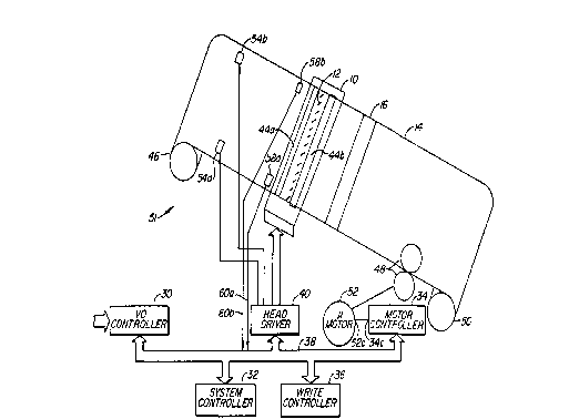
Referring to Fig. 1, a perspective view of a
print station 9 is presented. In Fig. l, a print head
10 includes a set of equally-spaced styli 12 disposed
in an elongate array. A sheet 14 of a print medium,
e.g., paper, is disposed below the print head and is
transported beneath the print head in the X direction
(longitudinal direction). The elongate array of styli
12 is oriented in the Y direction (lateral direction).
A toning station 16 is disposed beneath the paper 14
and displaced in the X direction from the print head
10. The toning station 16 includes means for flowing a
toning fluid onto the paper 14. The paper is dried
after the toning step. The print head and toner in
~ 3~
combination form a monochromatic primary image 18 of a
selected primary color.
The formation of a pr:imary image on the paper
14 will now be described in more detail with reference
to Fig. 2. In Fig. 2, two image lines 20A and 20B of
the image 18 are depicted. The second image line 20B
is disposed above the print head 10 and is being formed
by the styli 12. The styli 12, when activated, form
negatively-charged electrostatic dots 22A and 22B on
the paper 14. Each line 20 of the image 18 is formed
by a single scan of the styli 12.
The paper 14 is transported beneath the print
head 10 in the longitudinal direction at a near con-
stant rate. The time between scans is set so that the
distance, L, between image lines in the image is equal
to the distance, dy, between the dots in a particular
line 20 of the image, i.e., dy is equal to L.
The electrostatic dots 22A are not visible.
However, as the dots pass over the toner station 16
toning fluid is flowed onto the paper 14. This toning
fluid contains a liquid medium and positively-charged
colored pigment. The colored pigment adheres to the
paper 14 at the negatively-charged dots 22 and neutra-
lizes the dots. Thus, a rectangular array of colored
dots is formed which produces the desired image.
Colored areas of the image are formed where
negatively-charged dots 22 were printed by the activated
styli 12 and white areas of the image are formed in
those areas where styli 12 were not activated. As de-
picted in Fig. 2, each line 20 of the image includes NWdot positions or styli positions Si. The absence of a
negatively-charged dot 22 formed by an activated styli
12 results in a white dot in the final image. Accord-
ingly, colored or positive image dots result from a
negatively-charged electrostatic dot formed by a stylus
and white or negative dots result from the absence of a
negatively-charged electrostatic dot. The image 18
includes NL lines of dots.
Fig. 3 illustrates, in greater detail, an
embodiment of a print station 9 utilized in the present
invention. In Fig. 3 data and command information is
supplied from a source of data, e.g., a color control-
ler, to an I/O controller 30 which functions as an in-
telligent buffer for the information to be printed. A
system controller 32, motor controller 34, and write
controller 36 are connected by a command/control data
path 38. Write controller 36 is coupled to a head
driver 40 by the data path 38. Head driver 40 is coupled
to the print head 10. In addition to the elongate array
of styli 12, the print head also includes first and
second back planes 44A and 44B. A supply roller 46,
drive roller and pinch roller 48, and optional take-up
roller 50 form a transport path 51 for the medium 14.
A microstep motor 52 has its control input
52C coupled to the control output 34C of the motor con-
troller 34.
Marking stations 54A and 54B are coupled to
the write controller 36 by control line 56. Sensors 58A
and 58B are coupled to system controller 32 by sense
lines 60A and 60B.
The operation of the system depicted in Fig.
3 will now be described. Status information relative
to the operation of the print station is generated by
the write controller 36 and communicated to the input
controller 30 via the command/control data path 38, and
made available for transmission to a data source, e.g.,a color controller (not shown), by the I/O controller
30.
The motor controller 34 provides timed micro-
step pulses to the microstep motor 52. The microstep
motor 52 advances a fixed distance, a microstep, upon
the receipt of each microstep pulse. The microstep
motor 52 causes the paper 14 to advance by one micro-
~ ~7~t3~
step via the driver roller and pinch roller system 48 inresponse to the micropulse. Although the paper 14 is
advanced in microstep increments, the motion of the
paper is substantially continuous within the context
of the printing process.
The write controller 36 receives the micro-
pulses generated by the motor controller 34 via the
data path 38 and counts the microstep pulses. The write
controller 36 issues a write signal at upon counting a
set number of microstep pulses ( a step). This write
signal causes the head driver 40 to initiate a printing
scan to form a line of a primary image.
The number of microstep pulses in the step
between write signals determines the spacing between
the lines of the image. Because the timing between
write signals and the transport rate of the paper is
synchronized to the micropulses, the distance between
lines is determined by the number of micropulses in the
steps between write signals.
Fig. 4 is a schematic diagram of a single
pass electrostatic color printer. The paper 14 is ad-
vanced in the X direction by the transport path 51.
Each print station 9A, 9B, 9C, and 9D prints a primary
monochromatic image of a selected color. A full colored
image may be created by superimposing primary images of
the colors yellow, cyan, and magenta. Colors in the
visual spectrum are created by combining dots of these
primary colors in a region of the image. The dots may
be directly superimposed, e.g., the super imposition of
magenta and yellow produces a red dot, may be disposed
side-by-side, or may be disposed in a combination of
overlap and side-by-side registration. It has been
found however that a true black cannot be produced by
superimposition of the three primary colors and there-
fore an independent black print station 9D is included.
The raster data required to form a given colorimage is supplied to the plotter system from a color
~ ;~7~
-10-- 64157-200
controller (not shown). A system for supplying this raster data
is disclosed in a commonly assigned Canadian patent application
No. 522,023 entitled Color Plotter Controller (by Deering et al).
This data is received through the I/0 controller 30 and directed
to the write controller 36. The color controller 30 breaks a
color image into its primary components. The raster data for each
primary image is utilized by the write controller 36 to generate
physical data for controlling the activation of the styli 12 at
the print stations 13B through 13E. The raster data supplied from
the color controller consists of virtual data elements that
represent a virtual image. This virtual data is transformed in
the write controller 36 to physical data which is utilized by the
head driver 40 to control the activation of individual styli 12 in
the various print heads.
The physical color image formed by the printer/plotter
system is a superimposition of four primary images where the first
primary image is a monochromatic yellow and white image, the
second primary image is a monochromatic cyan and white image, the
third primary image is a monochromatic magenta and white image,
and the fourth primary image is a monochromatic black and white
image. As described above, the resulting colors in the composite
image are determined by the superimposition and close registration
of the various primary-colored dots. The primary images formed at
each of the print heads 9A through 9D must be precisely registered
to cause this superimposition and lateral registration to
accurately reproduce the colors of the virtual image and to
provide a high resolution image on the paper.
3~
-lOa- 64157-200
From Figure 4, it is apparent that the four prlmary
images of the final composite lmage are formed sequentially in
time. The yellow monochromatic primary image is formed flrst as
the paper passes below the yellow print station 9A. The yellow
primary image is passed below the cyan print station 9B where the
cyan
",, ~
primary image is superimposed on the first primary image.
Next, the magenta primary image is superimposed on the
composite yellow and cyan primary images at the magenta
print station 9C. Finally, the black primary image is
superimposed upon the combined yellow, cyan, and magenta
primary images to form the composite full-color image
at the black print station 9D.
The position of the print heads 9A through 9D
relative to the paper transport system 51 is mechani-
cally fixed. However, the paper may shift in the lat-
eral direction, stretch in the longitudinal direction,
and change in size (expand or contract) as a given area
of the paper is transported from one print station to
another. The expansion or contraction of the paper is
due primarily to humidity differences to which it is
subjected when rolled and unrolled.
Thus, even if the print heads 10 are mechan-
ically aligned and spaced relative to the transport
path 51, the primary images printed may not be regis-
tered due to lateral shift, longitudinal stretch, and
change of size of the paper. The present system pro-
vides for accurate, longitudinal, and lateral registra-
tion of the primary images formed at each print station
to provide a high resolution composite color image.
The operation of the invention will first be
described for the case of registering a second primary
image to a first primary image previously formed on the
paper. Without loss of generality, the case where the
first primary image is formed by a first printing sta-
tion 9A and the second primary image is formed by a
second printing station 9B will be described.
The lateral registration system of the present
invention will be described first. Fig. 5 illustrates
a first aspect of the lateral registration problem.
Referring to Fig. 5, line 20A is the first line of the
primary image and line 20B is the first line of the
secondary images. These lines are shown longitudinally
3~
-12- 64157-200
displaced to simplify the descrlption of the lateral registratlon
problem. In actuality, the line should be superimposed. In
Figure 5, the left margin 20BL of the first line prlnted in the
second primary image is displaced from the left margin 20AL of the
first line in the first primary image by a distance DY. This
displacement may be due to lateral paper shift in the transport
path 51.
Figure 6 depicts the stylus configuration of the print
head utilized in the present invention. For ease of description,
the styli 12 are shown disposed in a linear equi-spaced array. In
a preferred embodiment, a bi-scan print head having two rows of
styli 12 positioned in a staggered arrangement is utilized. These
print heads are fully-described in U.S. Patents Nos. 3,622,396;
3,653,065; 3,611,419; 3,657,005; and 3,342,164. The function of
the present system will be described with reference to the simpler
arrangement depicted in Eigure 6. The extension of these concepts
to a bi-scan head as described in the above-referred to patents or
a quadrascan head as described in United States Patents Nos.
4,419,679 and 4,417,391 by Rutherford et al., will be apparent to
persons of skill in the art.
-12a- 64157-200
Referring now to Figure 6, a total of NP styli 14 are
included in the array. Each raster line in the virtual image
includes NW virtual data elements. These vlrtual data elements
are transformed into physical data elements at the write
controller 36. The physical data elements are utilized to control
the states of NW styli to form the lines of the primary image.
Each stylus position is labelled by the index, i where Si is the
position of the ith stylus in the stylus array. The physical data
field includes NP physical data elements with the jth physical
data element determining whether the stylus at position 5i~ i ~ j,
is activated
~ 4
during a given scan. The write controller 36 trans-
forms the NW virtual data elements of a given raster
line into NW physical data elements corresponding to an
active region of NA styli. In this example, NA = NW.
The first stylus in the active region is at position
SA. The write controller 36 maps the first data element,
Vl, of the virtual raster line into the Ath physical
data element, PA. The unused styli at each side of the
active region form left and right slack regions.
Fig. 7 depicts the system utilized for deter-
mining the value of the quantity A needed to maintain
registration between the left margins of the image lines
of the first primary image and the second primary image.
In Fig. 7, the first primary image printing station 9A
and second primary image printing station 9B are de-
picted. The left registration marking system 54A pro-
duces a left registration line 60 on the paper 14. The
position of the left registration marker station 54A is
fixed relative to the styli positions in the printer
heads 10 at the first and second print stations 9A and
9B.
In fact, in the present embodiment, the marker
station utilizes styli in the slack regions of the first
print head lOA ànd special toning stations positioned
outside the image 18 to form the registration lines.
The active region of the first print head lOA forms image
lines of the first primary image which are toned yellow
and selected styli in the blask regions form the regis-
tration lines which are toned black. Alternatively,
the registration lines could be toned yellow and filters
utilized at the sensors to detect the registration lines.
Since the stylus positions, Si, utilized to generate the
registration line 60 is known, the position of the regis-
tration line 60 at the first print head lOA is known.
Sensor 58 at the second printing station 9B
measures the position of the registration line 60 rela-
tive to the stylus positions at the first printing head
lOB. The write controller 36 receives the stylus posi-
1~7~'3~
tion Si corresponding to the position of the registration
line measured at each head. The write controller 36 then
adds a fixed stylus increment, SI, to the stylus location
of the registration line 60 to determine the position of
the first stylus in the active region, SA. The distance
of the first stylus, SAl, of the active region in the
first print head 9A from the registration line 60 is D1.
The distance of the second stylus, SA2, in the second
print head 9B from the registration line 60 is D2.
In operation, a preliminary length of the
registration line 60 is generated prior to formation of
the primary images. The position of the registration
lines at print stations 9A and 9B is measured and
preliminary values of the first stylus position of the
active region, SA1 and SA2, are then determined so that
the left margins of the active regions at the two print
stations are laterally registered and D1 is equal to
D2.
During printing D2 is periodically measured
to determine any change in magnitude due to lateral
paper shift or change in size of the paper. If the
magnitude of D2 has changed, then the quantity A2 is
updated by the write controller 36 so that the magni-
tude of the distance from the registration line 60 to
the left margins of the corresponding lines in the first
and second primary image are e~ual. Thus, the left
margins of the first and second primary images are main-
tained in precise lateral registration.
Fig. 8 illustrates the virtual/physical data
transformation. In Fig. 8, the virtual data elements
VO through VNw are mapped into the physical data ele-
ments PA through PA+Nw. In the present embodiment, if
Pi is equal to one, then the stylus at position Si is
activated during a scan and, if Pi is equal to zero,
the stylus is not activated. In the transformation
illustrated, all Pi for i less than A and i greater
than A+NW are set to zero. These Pis define left and
7~3~
right slack regions, S1 through SA_1 and SA+N~+1 through
SNp in the stylus array. The active region of the sty-
lus array includes the stylus positions SA through SA+Nw.
The position of the active region of the stylus array
is varied by adjusting the value of the quantity A.
A block diagram depicSing circuitry in the
write controller 36 for implementing lateral registra-
tion correction and line enhancement is depicted in
Fig, 9.
Referring now to Fig. 9, the data path 38 is
coupled to input buffer 70. Input buffer 70 is coupled
to a parallel to serial virtual data shift register 72
by bus 74. The virtual data shift register 72 is coupled
to a serial to parallel physical data shift register 76
by serial bus 78. The physical data shift register 76
is coupled to output buffer 80 by data path 82.
Each shift register 72 and 76 includes parallel
and serial clock inputs. A transform unit 84 includes
CLK, OFFSET, and INCREMENT inputs and CLK 1 and CLK 2
outputs. The CLK input is coupled to a system clock
input 86, the OFFSET input is coupled to the output of
an OFFSET counter 88, and the INCREMENT input is coupled
to the output of an INCREMENT counter 90.
Both the INCREMENT and OFFSET counters 88 and
90 include counting inputs 88c and 90c coupled to the
CLK terminal 86 and data inputs 88d and 90d for receiv-
ing initial counter values from the system controller
32.
The serial clock input port of the virtual
data SR72 is coupled to the CLK 1 output and the serial
clock input of the physical data SR 76 is coupled to
the CLK 2 output.
An input counter 92 has a counter input cou-
pled to the CLK 1 output and an output port coupled to
the parallel clock input of the virtual data SR 72. An
output counter 94 has a counter input coupled to the
t~
16
CLK 2 output and an output coupled to the parallel clock
input of the physical data SR 76.
The output register 80 output ports are cou-
pled to the input ports of a delayed line buffer memory
96 and a vertical line enhancement and marker data gen-
erating unit 97. The unit 97 includes inputs coupled
to the outputs of a marker data generator 98a, a line
counter 98b, and a byte counter 9~c. The outputs of
line and byte counters 98b and 98c are also coupled to
the inputs of memory 96.
The operation of the circuit depicted in Fig.
9 will now be described. The virtual data is loaded
into the virtual data shift register 70 so that the
data element V1 is shifted onto the serial bus 78 first
and the data element VNw is shifted last.
The system controller 32 presets the initial
counter value of the OFFSET counter 88 to a value deter-
mined by the value of A required to register the left
margins of the lines of the first and second primary
images. Both the CLK 1 and CLK 2 output signals are
derived from the system CLK signal. The INCREMENT coun-
ter output is utilized by transformation unit 84 to
inhibit the CLK 1 signal for (A-1) counts while the CLK
2 signal causes (A-1) zeros to be shifted into the phy-
sical data SR 76. Accordingly, the physical data ele-
ments P0 through PA 1 are set equal to zero. The CLK 1
and CLK 2 signals are then clocked together for NW
counts to map the virtual data elements Vl through VNw
into the physical data elements PA through PA+NW. Fin-
ally, the CLK 1 signal is again inhibited for (NP-A-NW~
counts while the CLK 2 signal causes zeros to be shifted
into the physical data SR 76 to set the physical data
elements PA+NW through PNp equal to zero.
The input counters 92 and output counter 94
monitor the CLK 1 and CLK 2 signals, respectively, and
provide signals to cause a parallel data shift into SR
72 and out of SR 76 at the appropriate times.
7~
17
A detailed circuit diagram corresponding to
the block diagram of Fig. 9 is E;et forth in an Appen-
dix.
The second aspect of lateral registration
problem relates to aligning the right margins of the
lines of the first and second primary images. If the
left margins of the lines are aligned then misalignment
of the right margins is due to change of paper size
between the time that a given line in the first primary
lo image is printed and the time that the corresponding
line in the second primary image is printed.
Fig. 10 illustrates the case where the paper
has increased in size between the time that the lines
in the first primary image were printed and the time
that the line in the second primary image is to be
printed.
Referring to Fig. lO, the first primary image
line 20A has increased in size from Ll to L2 due to
paper stretch. The left margin of the first primary
line 20A and of the active region of the printer head
have been aligned as previously described. However,
the length of the active region of the second plotter
head is Ll. Thus, if a second image line were to be
printed, the second image line would be shorter than
the first image line and would not be laterally regis-
tered at the right margin. This lack of registration
results in poor resolution and poor color reproduction.
Accordingly, the present system adds styli to the active
region where the number of styli added is equal to NADD.
The number NADD is selected so that NADD is multiplied
by the distance between styli is equal to the differ-
ence between the length of the first line at the second
plotter head and the length of the active region, i.e.,
L2-Ll.
In the present embodiment, the ~uantity NA is
increased from NW by adding styli to the active region.
If the paper decreases in size from the first print
7~3
station 9A to the second print station 9B then image
lines 20b in the second primary image having NW dot
position (length Ll) would be longer than the image
lines 20a of the first primary image. Thus, the NA
adjustment must be made at the first print station 9A
because the NA of the active region cannot be less than
NW. A preliminary length of the first and second regis-
tration lines is sensed at the second print station 9B,
the distance between the registration lines, DR1 and DR2,
is determined, and the magnitude of the number of styli
(NADD) that must be added to the active region at the
first print head lOA is determined. The decrease in
paper size between the print stations cause the NW ~ NADD
dot position image line 20a of the first primary image to
be the same length as the NW dot position image line 20b
of the second primary image.
The total number of styli in the newly-defined
active region NA is equal to NW added to NADD. Since
only NW virtual data elements are supplied to the write
controller 36, the physical data elements to determine
whether the added styli are activated during a particu-
lar line scan must be generated by the write controller
36. Specific algorithms for determining the value of
these added physical data elements are described below.
However, a first problem is the placement of
the added styli. Fig. llA illustrates the problem of
placing the added styli. In Fig. llA the original
active region including the NW physical data elements
corresponding to the virtual data elements and the addi-
tional NADD styli reguired for right margin registration
are shown in a side by side relationship. Since the
NADD styli at the right margin are not included in the
image, the right margin correction would be an arbi-
trary pattern of dots unrelated to the image if the
styli were maintained in this relationship. An example
of placement of the styli to avoid this problem is de-
picted in Fig. llB. First, the added styli are evenly
~'~'7~3ti~4
19
distributed throughout the NW stylus positions repre-
senting the virtual image. Secondly, the position of
the added styli are randomized in a small interval,
e.g., _8 styli, around the first order evenly distri-
buted positions.
The need for randomization is especially cri-
tical in complex multi-colored regions of an image. If
a given added stylus always had the same stylus posi-
tion, then a line or artifact in the complex region of
the image would be created. By randomizing the posi-
tion of the added styli the effects of adding a dot
The system for inserting the extra styli will
now be described with reference to Fig. 9 and Fig. llC.
Referring to Fig. llC a section of the virtual/physical
data transformation is depicted. As described with
reference to Fig. 9, this transformation is achieved
utilizing SRs 72 and 76 and the CLK 1 and CLK 2
signals. A physical data element is to be added at
position (Pj+l) as determined by the system controller
32.
From Fig. llC, Vi is mapped into Pj and Vi+
into Pj+l. The CLK 1 is signal is then inhibited for
one count so that Vi+2 is not shifted from SR 72 to SR
76. The value of Vj+2 is determined by the write con-
troller as described below. The clocking of CLK 1 sig-
nal is again resumed and Vi+2 is mapped into Pj+3.
Referring to Fig. 9, the timing of the inhi-
bition of the CLK 1 signal to add physical data elements
is ccntrolled by the INCREMENT counter 90 output.
One method for randomizing the positions of
the added styli is as follows. The first order evenly
distributed added styli positions are specified by a
16-bit binary number. The least significant three or
four bits of this number are then replaced by the out-
put of a random number generator.
The system for longitudinally registering the
first and second primary images will now be described.
Referring to Fig. 12, a series of equally-spaced fidu-
cial marks 100 is placed on the paper by the marking
station 54A at the first print station 9A. These marks
are detected by the sensors 58 at succeeding print sta-
tions 9 and the time of detection is transferred to thesystem controller 32. The system controller 32 gener-
ates a first write signal when a selected one of a pre-
liminary series of marks 100 is printed at the first
print station. Succeeding lines of the first primary
lo image are printed at steps of 16 microsteps, each of
length dx, where the distance between steps is equal to
16dx. In the present context, a step is the distance on
the paper between image lines and also represents the
number of micropulses corresponding to the number of
microsteps between image lines.
Fig. 13 illustrates how paper stretch can
cause loss of longitudinal registration between the
first and second primary images. In Fig. 13, the paper
has stretched so that the distance between lines of the
primary image at the second print head is e~ual to (16
+ ~)dx. The write controller 36 generates the first
write signal when the selected fiducial mark 100 is
detected at the second print head. However, if suc-
ceeding second image lines are printed at steps of 16
micropulses, then the distance between lines in the
second image will be 16dx. Thus, a longitudinal regis-
tration error of ~dx will be introduced at every step.
In a typical example, the distance between
fiducial marks 100 at the first printer head is 1600
microsteps, 100 lines are printed between each fiducial
mark, and the distance or step between lines is 16 micro-
steps.
In the system of the present invention, the
system controller counts the microstep pulses between
the fiducial marks detected at the second print station 9B
to determine the quantity CN. If the paper has stretched
then CN will be greater than 1600. The difference be-
~'7~3~i~ 4
21
tween CN and 1600 is equal to the adjustment, ADJ, neededto correct for the longitudinal registration error.
Typically, the value of ADJ is less than 100, so that
~, the adjustment required at each step, is less than
one. The write signal is synchxonized to the microstep
pulses and the minimum correction that can be imple-
mented is one microstep.
An example of this correction process will now
be described with reference to Figs. 14A and 14B. Fig.
lo 14A depicts the case where the size of the paper has not
changed between the first and second print heads 9C and
9D. The number of microsteps, CN, counted between fidu-
cial marks 100 is 1,600 and the value of ADJ is zero.
Thus, the number of microsteps between lines, i.e., the
magnitude of each step, is 16 and no longitudinal cor-
rection is implemented.
In Fig. 14B the paper has increased in size
in the longitudinal direction. The value of CN is 1,610
and ADJ is 10. Thus the error, ~, at each step between
the fiducial marks 100 is 1/10 of a microstep. As de-
scribed above, the write signal timing is determined by
counting microstep pulses. Thus, the minimum correc-
tion to the length of a step is one microstep.
Fig. 14B illustrates the distribution of the
adjustment over the set of lines 20b of the second pri-
mary image. A one microstep correction is made at in-
tervals of ten steps. Thus, the 1st, 11th, 21st,
91st steps are seventeen microsteps long and all other
steps are 16 microsteps.
The system controller 32 determines the value
of CN and ADJ and generates a table of the number of
microstep pulses to be counted between each write sig-
nal. The resulting timing of the write signals assure
longitudinal registration between the image lines of
the first and second primary images.
If the paper decreases in size between the
first and second print stations 9A and 9B, then CN at
~.~'7~3~
the first station 9A is greater than CN at the second
print station 9B. The value of ADV in that case is a
negative number. The correction of the spacing between
image lines of the second primary image is implemented
by decreasing the size of the steps, separated by the
interval value, by one microstep.
The amount of longituclinal shrinkage is deter-
mined by counting the microstep pulses between the gene-
ration of successive marks 100 at the first print sta-
lo tion 9A and the detection of successive marks at thesecond print station 9B.
A line enhancement function is utilized to
select the value of the physical data elements added to
implement right margin lateral registration and to im-
prove image quality.
The line enhancement function includes twotypes of line enhancement algorithms. The first type
will preserve dotting patterns, e.g. (01010101) and the
second type fills a dotting pattern to all ones, e.g.,
(01010101) to (1111111).
The use of these line enhancement algorithms
to improve image quality will first be described. Two
horizontal lines in an image may be represented by the
virtual data elements 00100100. Generally, a line one-
dot thick is not desired. The system controller wouldimplement the first type enhancement algorithm to gen-
erate the physical data elements 011001100. Thus, the
line width is increased to two dots. The second type
of enhancement algorithm is utilized to prevent drop-
outs when filling an image region with colored dots.
These line enhancement algorithms may be uti-
lized independently of the stylus addition function.
The use of the second type of enhancement
algorithm to determine the value the added physical
data element for an image including two horizontal lines
will now be described.
23
Assume that the physical data elements repre-
senting the two lines, before insertion of the added
physical data element, is 01010. Let Z be the added
pixel element whose value is to be determined. If Z is
placed so that the physical data elements are OlOZ1
then Z is set to zero. If Z is placed so that the phy-
sical data elements are OlOlZ0 then Z is set to zero.
The determination of the value of the added
pixel in complex colored regions of an image is deter-
mined by a dithering technique.
Table 1 illustrates the outcome of the firstand second types of algorithms applied to a bit Z added
to an arbitrary virtual data set.
TABLE 1
15 Data SetValue of Z (Type 1) Value of Z (TYpe 2)
OOZO O O
OOZl
OlZ0
OlZ1
20 lOZ0 o o
lOZ1 0
llZ0 0 0
llZ1
For example, Fig. 15A depicts a dot array for
forming a pale red region in a composite color image.
Fig. 15B depicts the image with an added pixel, Z, in
the first line. The use of white dots, W, to form a
pale color is an example of a half-tone technique.
The pixel Z is added at the second toner sta-
tion 9A. Thus, if the physical data element corres-
ponding to Z is one then a magenta dot will be printed.
If the physical data element is 0 then a white dot will
be printed. Printing either a white or magenta dot a Z
will introduce a color error Ec into the pale red region.
3~
24
The dithering algorithm in the system control
adjusts the color values of surrounding dots to compen-
sate for Ec. The above-described randomizing is espe-
cially useful in half-toned or dithered regions to pre-
vent randomizing. For an image comprising lines, ran-
domizing is not used, the placement and activation of
the added styli is controlled by the line enhancement
function.
The sensing system 54 utilized in the present
embodiment will be described with reference to Figs.
16A-C. Fig. 16A depicts an optical CCD sensor 160A
positioned to receive light reflected from the paper
medium 14. The CCD detector comprises a shift register
of optical integration cells 162.
During an exposure cycle, light incident on
each cell 162 releases electrons which are stored at
each cell. The charge stored at each cell indicates
the intensity of the light incident in the cell 162
during the exposure cycle. The charge stored in each
cell 162 is sequentially measured during a read cycle.
Fig. 16B indicates the form of the read out-
put when the registration line 60 is positioned below
the CCD 160. The amount of charge stored in the cells
162 disposed above the registration line is less than
in cells 162 disposed over the white region of the paper
14 because the black line does not reflect much light.
A low pulse, PR, indicates the position of
the registration line. The position of PR is deter-
mined by counting the cells 160 as they are serially
read.
The fiducial marks 100 generate a wide pulse,
PF (Fig. 16C). The number of microstep pulses between
successive PFs is utilized to determine the ADJ value.
A second sensor lOOB measures the position of
the second registration line 60B. The distance between
registration lines is utilized to determine NADD.
The difference between the positions of the
PR pulse for successive readouts is compared to a thresh-
old TR. The value of A is updated if this difference
is greater than TR.
Fig. 17 depicts an alternate sensing arrange-
ment. In Fig. 17 the CCD sensor 160 is oriented at an
angle, e.g., 45, relative to the registration line 60.
This orientation allows two fiducial marks 60 to be
detected at one time. The distance between fiducial
marks 60 may be determined utilizing one readout cycle.
Fig. 18 depicts an alternate detection scheme
that utilizes styli in the slack region of the second
print station 13D as sensors.
Referring to Fig. 18, an electrostatic dot is
formed at a selected stylus, SE, at the first print
station 13D. This dot is not toned and, therefore, is
not neutralized.
At the second print head 13D a potential,
VD2, is maintained between the styli in the slack region
and the backplane. When the charged dot, formed at the
first print station 13C, passes over a stylus at the
second print head 13D VD2 at that stylus will change in
magnitude to the presence of the charged dot. This
change in VD2 is detected and the stylus location of
the dot at the second print head is determined.
A system for registering the primary images
of a composite color image that does not require mecha-
nical repositioning of the medium or print heads has
now been described with reference to preferred embodi-
ments. Various modifications and substitutions of partswill now be apparent to persons of ordinary skill in
the art.
In particular, other types of print heads may
be substituted for those described. Further, other
primary colors may be used and the order of colors may
be changed. Different systems for randomizing the place-
ment of added styli and distributing the adjustment to
.~'7
26
the spacing between image lines may be substituted.
Additionally, the adjustment to the length of the image
lines can be accomplished by decreasing the number of
styli in the active region.
Accordingly, it is not intended to limit the
breadth and scope of the invention except as provided
by the appended claims.