Sélection de la langue

Search

Sommaire du brevet 1280034 

Énoncé de désistement de responsabilité concernant l'information provenant de tiers

Une partie des informations de ce site Web a été fournie par des sources externes. Le gouvernement du Canada n'assume aucune responsabilité concernant la précision, l'actualité ou la fiabilité des informations fournies par les sources externes. Les utilisateurs qui désirent employer cette information devraient consulter directement la source des informations. Le contenu fourni par les sources externes n'est pas assujetti aux exigences sur les langues officielles, la protection des renseignements personnels et l'accessibilité.

Disponibilité de l'Abrégé et des Revendications

L'apparition de différences dans le texte et l'image des Revendications et de l'Abrégé dépend du moment auquel le document est publié. Les textes des Revendications et de l'Abrégé sont affichés :

  • lorsque la demande peut être examinée par le public;
  • lorsque le brevet est émis (délivrance).
(12) Brevet: (11) CA 1280034
(21) Numéro de la demande: 1280034
(54) Titre français: DISPOSITIF POUR MONTER ET TENDRE DES CLICHES SOUPLES SUR LE CYLINDRE DE PRESSE D'UNE ROTATIVE
(54) Titre anglais: DEVICE FOR MOUNTING AND TENSIONING ELASTIC PRINTING PLATES ON THE PLATECYLINDER OF A ROTARY PRINTING MACHINE
Statut: Périmé et au-delà du délai pour l’annulation
Données bibliographiques
(51) Classification internationale des brevets (CIB):
  • B41F 27/12 (2006.01)
  • B41F 27/00 (2006.01)
(72) Inventeurs :
  • JESCHKE, WILLI (Allemagne)
(73) Titulaires :
  • HEIDELBERGER DRUCKMASCHINEN AKTIENGESELLSCHAFT
(71) Demandeurs :
  • HEIDELBERGER DRUCKMASCHINEN AKTIENGESELLSCHAFT (Allemagne)
(74) Agent: DOUGLAS S. Q.C. JOHNSONJOHNSON, DOUGLAS S. Q.C.
(74) Co-agent:
(45) Délivré: 1991-02-12
(22) Date de dépôt: 1986-12-31
Licence disponible: S.O.
Cédé au domaine public: S.O.
(25) Langue des documents déposés: Anglais

Traité de coopération en matière de brevets (PCT): Non

(30) Données de priorité de la demande:
Numéro de la demande Pays / territoire Date
P 36 06 351.7 (Allemagne) 1986-02-27

Abrégés

Abrégé anglais


ABSTRACT
The invention relates to a device for mounting and tension-
ing elastic printing plates on the plate cylinder of a
rotary printing machine having tensioning rails assigned to
both ends of the plate, whereby a one-piece tensioning rail
is provided which permits tensioning as well as stretching
or contracting of the trailing plate end in a simple
manner, without affecting the practical operation.

Revendications

Note : Les revendications sont présentées dans la langue officielle dans laquelle elles ont été soumises.


- 6 -
THE EMBODIMENTS OF THE INVENTION IN WHICH AN EXCLUSIVE
PROPERTY OR PRIVILEGE IS CLAIMED ARE DEFINED AS FOLLOWS:
1. Device for mounting and tensioning elastic printing
plates on a plate cylinder of a rotary printing machine
having tensioning rails assigned to both ends of the
plate, whereby the tensioning rails are braced against
side walls of a cylinder channel for tensioning the
printing plate, and having means for stretching or
contracting a trailing end of said plate in axial
direction of the plate cylinder,
wherein a one-piece tensioning rail (9) is provided for
the trailing plate end (5),
wherein for the plate end (5) there is arranged a
clamping means (10) on the tensioning rail (9) in the
center region thereof, and
wherein in the end regions of the tensioning rail (9)
there are provided tensioning segments (15) which can be
actuated for stretching or contracting the plate end (5).
2. Device according to Claim 1,
wherein via bearing bolts (16) the tensioning segments
(15) are pivotally fastened to the tensioning rail (9)
and, for the printing plate end (5), are provided with
clamping areas (17) extending eccentrically to the
bearing bolt (16).
3. Device according to Claim 1 or 2,
wherein the tensioning segments (15) can be pivoted by
means of adjusting motors (19) which are pivotally
mounted at the tensioning rail (9).

- 7 -
4. Device according to Claim 1,
wherein the tensioning segments (15) include clamping
areas and opposite said clamping areas there are
inserted thrust bearings (22, 26) in the tensioning rail
(9), said thrust bearings supporting the axial movement
of the plate end (5).
5. Device according to Claim 4,
wherein the thrust bearings (22) consist of poly-
urethane and are provided with slits (25) arranged
transversely to the moving direction of the tensioning
segments (15).
6. Device according to Claim 4,
wherein the thrust bearings (26) are mounted on needle
bearings (27), so as to be axially displaceable with
respect to the plate cylinder (1).
7. Device according to Claim 2,
wherein the clamping areas (17) of the tensioning
segments (15) are coated with a sharp-edged corundum
layer.
8. Device according to Claim 1,
wherein the clamping means (10) consists of poly-
urethane and is engageable by means of adjusting screws
(11) which are braced against the tensioning rail (9)
via a bearing (12).
9. Device according to Claim 2,
wherein, opposite the clamping areas (17) of the
tensioning segments (15), there are inserted thrust
bearings (22, 26) in the tensioning rail (9), said
thrust bearings supporting the axial movement of the
plate end (5).

- 8 -
10. Device according to Claim 9,
wherein the thrust bearings (22) consist of poly-
urethane and are provided with slits (25) arranged
transversely to the moving direction of the tensioning
segments (15).
11. Device according to Claim 9,
wherein the thrust bearings (26) are mounted on needle
bearings (27), so as to be axially displaceable with
respect to the plate cylinder (1).
12. In combination with a plate cylinder having a
transverse channel, with sidewalls, formed therein, a
device for securing a flexible printing plate under
tension on the plate cylinder, a tensioning rail
operatively associated with each end of the plate and
being braceable against the side walls of the
transverse channel formed in the plate cylinder for
tensioning the printing plate, comprising means for
selectively stretching and/or compressing at least one
of the ends of a printing plate in the axial direction
of the plate cylinder, the tensioning rail operatively
associated with the one plate end being of one-piece
construction and having a clamping member disposed at a
middle region thereof and respective tensioning
segments disposed at end regions thereof and means to
selectively actuate the tensioning segments, for
stretching and/or compressing the one plate end.
13. Device according to Claim 12,
wherein said tensioning segments are pivotally fastened
by bearing bolts to the one tensioning rail associated
with said at least one end and are formed with clamping
surfaces extending eccentrically to the bearing bolt
for engaging respective surfaces of the one plate end.

- 9 -
14. Device according to Claim 13,
wherein respective servomotors pivotally mounted on the
one tensioning rail associated with said at least one
end for pivoting said tensioning segments.
15. Device according to Claim 13,
including thrust bearings embedded in the one
tensioning rail associated with said at least one end
opposite said clamping surfaces of said tensioning
segments, said thrust bearings supporting the one plate
end for movement in axial direction of the plate
cylinder.
16. Device according to Claim 15,
wherein said thrust bearings are formed of polyurethane
and are provided with slits extending transversely to
the moving direction of the tensioning segments.
17. Device according to Claim 15,
wherein said thrust bearings are mounted on needle
bearings for axial displacement with respect to the
plate cylinder.
18. Device according to Claim 15,
wherein said clamping surfaces of said tensioning
segments are coated with a sharp-edged corundum layer.
19. Device according to Claim 12,
wherein said clamping member is formed of polyurethane,
and including set screws braceable against the one
tensioning rail via a bearing so as to engage with said
clamping member.
20. Device according to Claim 12,
wherein said one plate end is the trailing end of the
plate.

Description

Note : Les descriptions sont présentées dans la langue officielle dans laquelle elles ont été soumises.

1~(;)()34
.~ i ~ F~ ~ / A-477 25.02.1986
"Device for mounting and tensioning elastic printing plates
on the plate cyLinder of a rotary printing machine"
The invention relates to a device for mounting and tension-
ing elastic printing plates on the plate cyLinder of a
rotary printing machine having tensioning rails, which are
assigned to both ends of the plate and braced against the
side walls of a cylinder channel for tensioning the print-
ing plate, and having means for stretching or contracting
the trailing plate end in axial direction of the plate
cylinder.
Such a device is known from the DE-PS 23 10 228, in which
there are assigned to the rear plate end two pairs of
tensioning rails which enable the forming of the rear end
of the printing plate by means of adjusting screws. These
two pairs of tensioning rails can be moved circumferential-
ly in order to tension the printing plate as well as in
axial direction towards the plate cylinder. Thus, it is
possible to stretch the rear plate end, e.g. in the case of
the so-called "narrow printing", so that an exact register
is obtainable. However, with the rear tensioning rail being
divided it is difficult, in practical operation, to prevent
the tensioning rail consisting of several sections from
buckling.
On the basis of this prior art it is the object of the
invention to construct a device for mounting and tensioning
elastic printing plates on the plate cylinder in such a way
that the tensioning as well as the stretching or contract-
ing of the trailing plate end can be performed in a simple
manner, without affecting the practical operation.

1~800;~4
~E~s /A-477 25.02.1986
-- 2
According to the characterizing part of Claim 1, this
object is solved by providing a one-piece tensioning rail
for the trailing plate end, arranging a clamping means for
the plate end in the center region of the tensioning rail
and by providing in the end regions of the tensioning rail
tensioning segments which can be actuated in order to
stretch or contract the plate end.
Due to this one-piece construction of the tensioning rail,
a great stability is reached so that said tensioning rail
can be adjusted circumferentiaLly for tensioning the print-
ing pLate as well as laterally, w;thout caus;ng problems.
Thus, a uniform mount;ng and tensioning of the printing
plate is guaranteed, whereby, when the printing plate is
tensioned, the trailing plate end can be stretched or
contracted via the tensioning segments. The clamping means
provided in the center region avoids an unintended lateral
displacement of the plate end so that the adjusted register
is absolutely maintained. Due to the arrangement of the
tensioning segrnents in the end regions of the tensioning
rails, the stretching or contracting of the plate end is
effected in a very extended range so that the plate end is
prevented from arching or tearing.
The dependent claims characterize advantageous embodiments
of the invention which guarantee a reliable and easy hand-
ling of the device by using simple means.
One embodiment of the invention is schematically illus-
trated in the drawings described hereinafter:
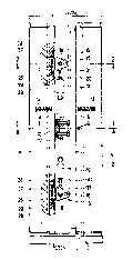
Fig. 1 shows a fragmentary cross-section of the device
according to the invention as indicated by the
' line 1.1 in Fig. 4;

~ F~ ~ ~ ~) ~ /A-477 25.02.1986
Fig. 2 shows a fragmentary cross-section as indicated by
the Line 2.2 in Fig. 4;
Fig. 3 shows a fragmentary top view of the lateral ten-
sioning device;
Fig. 4 shows a top view of the plate cylinder and the
device according to the invention.
~ith the fragmentary cross-section in Fig. 1 a plate cylin-
der 1 of a sheet-fed offset printing machine carries an
elastic printing plate 2 in a known manner which is ten-
sioned via tensioning means. A cyLinder channel 3 extending
over the length of the cylinder body of the plate cylin-
der 1 serves to receive said tensioning means. The leading
plate end 4 and the trailing plate end 5 are angled in
register in a bending device. For tensioning the leading
plate end 4 is hooked in at a tensioning rail 6 and held in
place by a spring 7. Fitting pins 8 serve for the exact
alignment of the front plate end 4. As soon as the front
plate end 4 is clamped, the plate cylinder is turned by one
revolution for mounting the printing plate 2 so that the
trailing plate end 5 can also be hooked in at a tensioning
rail 9. In the center region of the tensioning rail 9 there
is provided a clamping means 1û which preferably consists
of polyurethane, is engageable with the angled region of
the trailing plate end 5 by means of adjusting screws 11
which are braced against the tensioning rail 9 via a bear-
ing 12 and clamps said angled region of the trailing plate
end. Thereafter, the printing plate 2 is tensioned on the
plate cylinder 1 via compression springs 13 so that both
tensioning rails 6 and 9 are caused to assume the positions
illustrated in Fig. 1. In this case, both plate ends 4 and
5 are located under a covering plate 14 which prevents said
plate enos from slipping out. The untensioned position of
the tensioning rail 6 is indicated by a dash-and-dot line
in Fig. 1.

Er~ F~r~; _ 4 _ 25.02.1986
Figs. 2 and 3 show the tensioning segments 15 being pro-
vided on both sides of the tens;oning rail 9 in the end
regions thereof and being pivotally fastened to the ten-
sioning raiL 9 via bearing bolts 16. Towards the plate
end 5 the tensioning segments 15 are equipped with a clamp-
ing area 17 which extends eccentrically with respect to the
bearing bolt 16 and has a neutral middle position (as
indicated). When the tensioning segment 15 is pivoted to
the right or to the left, the plate end 5 is first clamped,
due to the eccentric construction of the clamping area 17,
and thereafter slightly displaced in axial direction so
that the plate end 5 is stretched or contracted. The in-
clination of the eccentric clamping area 17 causes an
additional clamping force during stretching and contracting
and acts self-locking.
By means of a bolt 18 an adjusting means engages at the
tensioning segment 15 which can be laterally pivoted by
said adjusting means. In a simple construction this adjust-
ing means is an adjusting screw which can be turned by
hand. Contrary thereto, Figs. 2 through 4 show pivoting by
means of an adjusting motor 19 which causes pivoting of the
tensioning segment 15 via a thread 20 and a fork lever 21.
With manual adjustment, the plate end 5 is stretched or
contracted at standstill of the machine and with adjustment
by motor this function is carried out at standstill or
while the machine is running. In order to ensure an exact
adjustment of the tensioning segments 15, the clamping
areas 17 thereof can be coated with a sharp-edged corundum
layer.
In Fig. 3, opposite the clamping area 17 of the tensioning
segment 15, there is provided below the plate end 5 a
thrust bearing 22 which is mounted in a recess 24 of the
tensioning rail 9 via screws Z3. This thrust bearing may

1;~800~4 .
r~ L~ / A-477 25.02.1986
- 5
consist of polyurethane and have slits 25 provided trans-
versely to the moving direction of tensioning segments 15.
Said slits support the lateral movement of the pLate end 5
while stretching or contracting the Latter.
Fig. 4 shows a different thrust bearing 26 serving the same
purpose but being mounted on needle bearings 27. The thrust
bearing 26 is retained in the recess 29 by means of fix-
tures 28 in such a way that it can be longitudinally dis-
placed.
In this illustrated embodiment normally both tensioning
segments 15 are uniformly pivoted by a sLight amount de-
pending on how much the the trailing plate end is being
corrected. The clamping of said plate end with the clamping
means 10 also permits, if required, a one-sided correction
by actuating only one tensioning segment 15. Irrespective
of this fact, there can be performed by the pressman any
desired adjustment of the one-piece tensioning rail 9 due
to its stable mounting, without undesirably affecting the
tensioning quality.

Dessin représentatif
Une figure unique qui représente un dessin illustrant l'invention.
États administratifs

2024-08-01 : Dans le cadre de la transition vers les Brevets de nouvelle génération (BNG), la base de données sur les brevets canadiens (BDBC) contient désormais un Historique d'événement plus détaillé, qui reproduit le Journal des événements de notre nouvelle solution interne.

Veuillez noter que les événements débutant par « Inactive : » se réfèrent à des événements qui ne sont plus utilisés dans notre nouvelle solution interne.

Pour une meilleure compréhension de l'état de la demande ou brevet qui figure sur cette page, la rubrique Mise en garde , et les descriptions de Brevet , Historique d'événement , Taxes périodiques et Historique des paiements devraient être consultées.

Historique d'événement

Description Date
Inactive : CIB de MCD 2006-03-11
Inactive : Demande ad hoc documentée 1994-02-12
Le délai pour l'annulation est expiré 1993-08-14
Lettre envoyée 1993-02-12
Accordé par délivrance 1991-02-12

Historique d'abandonnement

Il n'y a pas d'historique d'abandonnement

Titulaires au dossier

Les titulaires actuels et antérieures au dossier sont affichés en ordre alphabétique.

Titulaires actuels au dossier
HEIDELBERGER DRUCKMASCHINEN AKTIENGESELLSCHAFT
Titulaires antérieures au dossier
WILLI JESCHKE
Les propriétaires antérieurs qui ne figurent pas dans la liste des « Propriétaires au dossier » apparaîtront dans d'autres documents au dossier.
Documents

Pour visionner les fichiers sélectionnés, entrer le code reCAPTCHA :


Pour visualiser une image, cliquer sur un lien dans la colonne description du document. Pour télécharger l'image (les images), cliquer l'une ou plusieurs cases à cocher dans la première colonne et ensuite cliquer sur le bouton "Télécharger sélection en format PDF (archive Zip)" ou le bouton "Télécharger sélection (en un fichier PDF fusionné)".

Liste des documents de brevet publiés et non publiés sur la BDBC .

Si vous avez des difficultés à accéder au contenu, veuillez communiquer avec le Centre de services à la clientèle au 1-866-997-1936, ou envoyer un courriel au Centre de service à la clientèle de l'OPIC.


Description du
Document 
Date
(aaaa-mm-jj) 
Nombre de pages   Taille de l'image (Ko) 
Revendications 1993-10-14 4 109
Dessins 1993-10-14 2 54
Abrégé 1993-10-14 1 8
Description 1993-10-14 5 136
Dessin représentatif 2001-07-18 1 9