Note : Les descriptions sont présentées dans la langue officielle dans laquelle elles ont été soumises.
jl ~280279
~l APPARATUS FOR CONTINUOUS PAN COATING
!i
BACKGROUND gF THE_ INVENTION
The present invention relates to the art of coating
edible cores, and~ in particular, to a method and apparatus
for continuous pan coating edible cores.
The practice of applying a coating to edible
particulate matter or cores by pan coating generally includes
placing the cores in a rotating drum which continuously
. l agitates them while a solution of the coating material is
Il applied, usually by spraying the material over the cores in
il the rotating drum during agitation. It is custo~ary to coat
edible cores such as nuts, chewing gum, candies, fruits,
lozenges, dragees, and medicinal tablets with one or more
layers of candy or sugar coating by conventional procedures
i using a drum or a rotatable vessel and warm air or other
drying gas to evaporate and/or harden each layer in prepara-
tion for application of subseguent layers.
P ~ example, U.S. Patent ~o. 4,334,393 to Okawaru
i shows a rotary drum type apparatus for applying a coating to l I
tablets which includes a rotary drum supported by a frame for
receiving a body of tablets to be coated by spraying with a
! solvent~ The drum which can be inclined through about 10-20
in such a manner that its front surface is turned upwardly, ~ ;
¦I includes a device which supplies a coating material into the ~ l
interior of the drum and an inlet tube and an outlet tube to
provide a supply of drying gas such as air to the interior.
! ~
,. I
128 [)27~
- The support frame cooperates with an outer periphery of the
drum to define an air suction duct disposed on the front side
;of the support frame and an air exhaust duct disposed on the
' rear side of the support frame so that a smooth flow of hot
il blast through the drum can be obtained.
Similarly, in U.S. Patent No. 4,245,58C to Okawaro,
a device for coating granular solids is disclosed which has a
il double-cone rotary drum perforated so as to permit flow of air
~j or gas into and out of the rol:ary drum, and which is tiltable
about the axis at right angles to the axis of rotation of the j
Il rotary drum so that ln the case of the discharye of product
l~; solids, the opening of the rotary drum may be directed down-
li wardly. Axial annular insulating covers are providing which
i insure the effective thermal insulation of the rotary drum
¦ when the hot air or gas is blown thereinto. ~owever, each of
jl the Okawara disclosures discussed above relate to coating
drums for batch operation since each body of cores to be
coated must be fed into and discharged from a single opening.
Similar operation and apparatus are shown in U.S. Patent No.
3,448,718; U.S. Patent No. 3,063,843; and U.S. Patent No.
i 2,726,959.
Il I
¦ U.S. Patent No. 3~911,860 to Nohynek discloses a
coating drum for continuous coating of dragees with a coating
material and for subsequent application and glossiny of a
D protective skin over the coating by use o~ a co-axially
j, connected after-treatment drum. In particular~ both drums are
j fixed in a sealing connection to each other and may be driven
at different speeds by means of a variable speed transmission
i' rotationally interconnected. The dragee drum shown by Nohynek
l l
-2-
.,. . :
~ 2 ~
is a double frustum, while the after-treatment drum is
cylindrical. Both drums are equipped with conveying baffles
; in order to push the product through from the entrance to the
exit. On the inner wall of the rear frustum of the dragee
drum are located conveying baffles 5 arranged in relation to
~I the direction of rotation so that only a few dragees at a time
!1 are discharged through rear discharge opening 6. The
i discharge opening 6 leads to an inner drum 7 of approximately
the same diameter through which the coated particles flow by
means of conveying baffles ll to radial transfer opening 17
into intermediate drum 10 on which there are also located
helical screw type conveying baffles 5 and 13. The particles
pass from intermediate drum 10 into the outer drum space 20
i from which they emerge through discharge openings 21.
In each of these disclosures, as well as general
practice in the art, there is lacking a method and apparatus
for continuous pan coating of edible cores in whi~h there is a
hiqh degree of control of the coating process.
l I
Accordingly, it is an object of the present
lll invention to overcome problems normally associated with the
¦I continuous highly controlled pan coating of edible particulate
matter or cores.
' !
!i It is another obiect of the present invention to
¦! provide an apparatus for continuous pan coating o~ edible
cores with several layers of ~o ing material.
~2~279
It is a further object of the present invention to
provide an apparatus whereby edible cores can be provided with
a chocolate candy coating, as well as successive protective
outer coatings over the chocolate coating.
~ .'
SUMMARY OF HE INVENTION
In accordance with the present invention, an
i~ apparatus is provided which is useful for continuous pan
i coating of edible cores which includes, in combination, a
jl coating drum arranged for rotation around an inclined axis and
having an inlet opening at the upper axial end of he coating
i drum for reception of edible cores and a discharge opening at
j the lower axial end of the coating drum, and preferably means
i for controlling the incline of the drum to vary the degree of
force exerted by gravity urging the cores through the drum
during the panning operation. There is further included a
¦ means for continuously driving the coating drum, means for
delivering coating material to the cores at a controllab1e
i rate, and means for delivering drying gas o ~he cores at a
j, controllable rate while the cores are in the coating drum.
D Also included in the present apparatus is at least
one after-treatment drum likewise arranged for rotation around
an inclined axis and having an inlet opening at the upper
axial end of the after-treatment drum for the reception of
~¦ coated cores from the coating drum, and a discharge opening at
, the lower axial end for the discharge of treated coated cores.
r !l Also, a means for continuously driving said at least one
j after-treatment drum is provided, as well as a means for
continuously conveying the coated cores from the discharge end
~ 2 ~ ~
of the coating drum to the inlet opening of the
after-treatment drum. Finally, a means is provided for
applying the after-treatment coating at a controllable rate to
the coated cores during passage of the cores through the
after-treatment drum.
I In a preferred embodiment of the present invention,
ii there is further provided a second after-treatment drum
arranged for rotation as in the at least one after-treatment
j drum and also having features or characteristics similar to
I those of the after-treatment drum, such as a means for
il continuously driving the second after-treatment drum, means
ll for continuously conveying the cores from the discharge of the
jj first after-treatment drum to the second after-treatment drum,
i as well as means for applying a second after-treatment coating
, to the after-treated coated cores.
Il !
~¦ In order to provide a means for controlled delivery
li f the coating in the coating drum, the present invention
jj includes in one embodiment a coating manifold extending
, lengthwise in the interior of the coating drum with adjustable
i coating nozzles, preferably four in number, arranged along the
length thereof for controlling the amount of coating material
delivered to the cores. The means for delivering the coating
also includes a control means for selectively adjusting each
of the nozzles from a location exterior of the coating drum.
The coating manifold preferably includes a continuous conduit
1 connected for fluid communication with a source of coating
ii material and with each o~ said adjustable nozzles whereby
fluid coating material is provided to the nozzles.
5--
128~2~
Adjustable nozzles for use in the present invention
can include a nozzle housing having a coating supply bore with
~ an exit port, a movable means for restricting the fluid flow
; through the exit port which is responsive to means for
adjusting the flow restriction means. ~he adjustment means is
preferably fixed to the nozzle housing at a location exterior
thereto and operable to adjust the flow restriction means.
The movable means foir restric ing flow can be a pin element
slidably mounted in the bore and connected to the adjusting
means for linear movement through the bore.
In a preferred embodiment of the invention, the
j control means include nozzle adjustment stations mounted
~'1 interiorly of the coating drum at positions adjacent to
,i nozzles along the coating manifold, a rod member secured for
l~ rotation adjacent the coating manifold and parallel thereto,
!l the rod member having fixed thereon rotating adjustors at
i positions on the rod member wherein each rotating adjustor caA
j be selectively engaged with, and disengaged from, a nozzle
,¦ adjustment station by linear movement of the rod member. This
!j embodiment also contemplates use of a means for varying the
f position of the rod member linearly with respect to the
coating manifold, as well as means for rotating the rod member
which is fixed on the end of the rod member at a position
exterior to the coating drum.
¦j A nozzle adjustment station which can be used with
the above-described apparatus includes means for securing the
1~ rod member for rotation, an interconnecting drive means fixed
i to the means for securing the rcd member which drives the
; manifold nozzle adjustment means in response to rotation of a
~ 2 ~
rotating adjustor engaged therewith. The interconnecting
drive means can include a drive rod with a first end adjacent
to the nozzle adjustment means with a first driYing gear ~eans
; fixed thereon for driving the nozzle adjustment means, and a
j, second end with a second driving gear means fixed thereon
¦l proximal to the rotating adjustor which can be selectively
'j engaged with the rotatinq adjustor by linear displacement of
the control rod. Thus, the interconnecting drive means and
the nozzle adjustment means can be driven upon rotation of the
control rod while the rotating adjustor and the second gear
l means are engaged.
¦ To provide a means for varying the linear position
' of the rod member, a linear-shift housing can be mounted at
i'i the end of the rod member exterior to the coating drum through
¦, which the rod member extends, and a linear rod c~ntrol sleeve
fixed around the rod at the position on such rod which extends
through the housing. The control sleeve has adjusting
elements formed thereon which coact with the linear-shift
i housing to hold the rod member in position whereby each of the
rotating adjustors can selectively be engaged with a second
gear means at each adjustment station.
Further in accordance with the present apparatus,
j there is provided a means for delivering drying gas at a con-
!! trollable rate which includes a drying gas manifold mounted
interiorly along the length of the coating drum which has
I adjustable gas delivery ports provided along the length
1ll thereof, preferably four each, and means for controlling the
li flow of drying gas tbrough the gas delivery ports from a
1 location exterior of the coating drum. Preferably, each of
., ,
~ -7-
'' ''' '
~ 2 ~2 ~
the drying gas delivery ports includes an exit orifice having
a baffle mounted therein for rotation across the orifice,
while the means for controlling the flow of the drying gas
includes linking means extending from a control handle
exterior of the coating drum to each of the baffles for
rotating such baffle so that gas flow through the respective
exit orifice is controlled.
Il I
¦i As a result of the present invention, a highly con- I
! trolled apparatus and method for continuously applying a candy
- ; coating, especially chocolate, is provided in which subsequent
protective and appearance-improving coats can be applied on a
continuous basis without interruption of flow of edible
particulate matter or cores.
For a better understanding of the present invention
together with other and further ob;ects, reference is made to
j the following description, taken in conjunction with the
, accompanying drawings, and its scope will be pointed out in
the appended claims.
! BRIEF DESCRIPTION OF~ DRAWINGS
i Preferred embodiments of the invention have been
chosen for purposes of illustration and description and are
shown in the accompanying drawings wherein:
ii ~ .
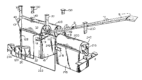
Fig. 1 is a perspective view of an overall system
for continuous pan coating in accordance with the present
invention; 1i
--8--
1;;~80Z7~
Fig. 2 is an elevated end view of the combined
apparatus taken from the left hand side of Fig. l;
Fig. 3 is a plan view of the combined apparatus of a
preferred embodiment Or the present invention:
Il Fig. 4 shows control apparatus mounted for operation
jl at the discharge end of the coating drum as depicted in
¦ Fig. l;
~! Fig. 5 depicts a portion of the inside of a coating
drum which includes a coating material recovery ~eature of the
, present invention;
Fig. 6 shows a controlled coating delivery system
according to the embodiment of the present invention depic-
.ed in Fig. 4.
il 1.
, Fig. 6a is a cross-section of the coating material
delivery manifold taken along lines 6a-6a;
Fig. 7 is an enlarged view o~ a portion of the
! control system shown in Fig. 6;
il, i
Fig. 8 is an enlarged view of a control station of
Fig. 6 in partial section;
Il . ~
Il Fig. 9 is a section view taken along the line 9-9 of
~ig. 8 and
; --9 _
:~L28~27~ .
~~ Figs. 10-14 depict a controllable drying gas
delivery system in accordance with the embodiment of the
present invention depicted in Fig. 4.
DETAILED DESCRIPTION OF THE INVE~
. i .
Il Each of the drawings depicts so much of that part of
; the particular embodiment of the invention which is required
to provide an adequate understanding thereof. The surrounding
or connected portions of the apparatus which are not shown or
detailed in each drawing are understood as being part of the
- state of the art or are depicted in accompanying related
drawings.
l Referring to Figs. 1, 2 and 3, there is shown a
combined apparatus in accordance with a preferred embodiment
of the present invention in which a coating drum 10 is shown in
series with a first after-treatment drum 100 and a second
after-treatment drum 200. Particulate core material 12 is
i delivered from a source via conveyor means 9 into receiving
end 11 of the coating drum 10. The coating drum 10 is mounted
on a support 16 at an incline which is pitched downwardly from
receiving end 11 towards discharge end 13. ~he angle or pitch
of the drum, as well as the speed of rotation of the drum,
provided by continuously moving drive belt or chain 19 and
drive motor 18, can be varied by conventional means. The
¦ angle of the drum and the rate is generally determined by the
amount of coating and the rate of product feed. Furthermore,
j as seen in Fig 2, product volume control is also e~fected by
use of a product retainer plate 6, which can be affixed to the
exit end 13 of drum 10.
--10--
.
~2ao~79 61293-125
Gravit~ flow, along with drum rotation, are the
primary means by which the product flows through the present
continuous pan coatin~ system. Conventional conveying meansr
such as endless belts, can also be used between coating dr~ms
if the drums are not located one below the other. In a
preferred mode of operation, a scraping and scrap removal
means is also provided in the coating drum 10 to insure
continual tumbling of the particulate matter being coated as
well as to avoid coating build-up which requires production
shut-down for clean-up. In Pig. 5 there is shown a portion o
a drum interior which has a drum wall 8 having ribs 7 which
effect forward travel of particles as they tumble during drum
rotation. In order to prevent coating material build-up as
well as particle back-flow against the particulate mass, a
notched scraper 4 can be mounted along the length of the drum
over several of the ribs 7 at a point which does not interfere
with the coating process. These problems are associated with
continuous coating processes, and are not incurred in batch
operations wherein alternate or supplemental equipment usage
avoids coating build-up, etc~
As shown in Fig. 2, each of the drums can be mounted
at a position lower than the drum before it, i.e., the
treatment drum 100 is slightly below coating drum 10, and is
mounted higher than second after-treatment drum 200. Each of
the drums has its own source of continuous rotation, shown as
motor 118 and continuous belt 119 in the case of
after-treatment drum 100, and as motor 218 and continuous belt
219 for the second after-treatment drum 200. The direction of
flow of particulate matter is shown in Fig. 3 as originating
from conveyor belt means 9 through drum 10, and thence into
drum 100 via conveyor 101. The partlculate mass s pass~ad
-11-
128027'9
61293-125
through drum 100 where it is further coated or treated and then
moved to the receiving end 113 of drum 200 via convayor 201 and
then through drum 200 to its discharge end 213. The drum 200 is
mounted on a support 216 as depicted in Figure 1.
Referring specifically to Figs. 1 and 3, a source of
; coating material is shown for each of the drums. Vessel 20
provides the coating material for the coating drum 10 via line 22;
vessel 120 provides a source of ater-treatment material via line
122, while vessel 220 is a source of material, such as a final
coating, for second after-treatment drum 200 and is provided by
means of supply line 222. There is also shown in Fig. 1 an
overhead support means for the separate delivery systems for each
of the drums. In the case of the coating drum 10, there are shown
overhead support member 30 which also support scrap removal as
well as the delivery system; in the case of drum 100, there are
shown an overhead support members 130; while for drum 200,
overhead support member 230 is shown. Finally, with reference to
Fig. 1, drying-gas delivery conduits 40, 140 and 240 are shown for
each of the drums, as well as final product receiving conveyor
manes 2.
Fig. 4 shows a support member 30 and the delivery
control system from the discharge end 13 of coating drum 10. The
control system is mounted on support member 30 by means of an
angle/elevation rod 32 attached for rotation to support beam 33.
As shown in fig. 4, the rod 32 can be elevated or depressed in an
angular direction be means of angle adjustment 34, while the
position of the delivery control sys-tem along the length of rod 32
" ~2~3~X~79
61293-125
can be varied by means of clamping adjustment sleeve 35. Coating-
supply adjustment rod 36 which can be moved longitudinally along
its length and clamped to secure the coating supply system support
70, 70a at the desired
- 12a -
~21302~3
- position. Basically, the coating supply system should be
adjusted to a position at which the coating spray is directed
to the middle o~ the particle mass in the drum.
.' :
!~ Referring to Figs. 4-B inclusively there is shown
the coatin~ distribution system o~ the present invention which
includes primarily a coating material distribution manifold 74
j in combination with a control mechanismr the primary
component of which is control rod 73. The coating manifold 74
is connected for fluid communication with a source of coating
'~ material and also with each of the controllable coating
!j nozzles 75, preferably four in number. The coating manifold
74 can be constructed such that temperature control can be
j maintained by means of adjacent conduits 74c through which a
¦' medium, such a~ warm water, can be continuously passed (See
j Fig. 6a). Thus, a coating material such as chocolate can be
continuously fed through manifold feed conduit 74b without
incurring blockage due to freeze-up.
For ease of assembly, the control rod 73 can be
composed of rod segments which are joined at non-interferring ~ -
,1 positions along the length thereof by any conventIonal joining
! means, such as coupling 77. Tha control rod 73 can be mounted
to the support means ~0 by bearinged mounting brackets 78
which abut directly onto the mounting means 70 or,
alternatively, to adjustment control station plates 70a.
At the end of the control rod, exterior to the
coating drum, there is shown ~see Fig. 6) a linear control
housing 76 and, in phantom, a linear control sleeve 79
surrounding the control rod on that portion of the control rod
-13-
,
8~:)2~
which passes through the housing 76. By use of this housing
and sleeve combination in conjunction with the control pin 72
the control rod can be selectively displaced at different
linear positions relative to the manifold 74 so that each of
the nozzles can be individually adjusted to control the flow
of coating material through the nozzles 75. This operation,
' which is relatively simple, includes extracting tensioned pin
~-j 72 away from the housing and out of a depressed portion of the
sleeve 79 while the rod is moved in the linear direction to
position each of the rotatable adjustors 69 next to a control
station before the tensioned pin 72 is allowed to return to
the fully set position. When the control rod is in the
selected adjustment position, the rod may be rotated by means
of control handle 71 which is exterior to the coating drum,
' preferably at the product exit end. The control rod is also
provided with rotatable adjustors 69 which coact in coopera-
tion with the nozzle adjustment stations, designated generally
80 to provide a means for selectively adjusting each-of the
~! nozzles 75.
¦ Focusing on the control stations 80, there can be
seen a linking rod B2 mounted for rotation on mounting
brackets 78 generally directly below the control rod 73. ~he
linking rod 82 has a first end which is adjacent the control
mechanism on the adjustable nozzle 75 having a first gear
means 83, and a second end having a second gear means 84 to
¦I which rotating adjustors 69 can be engaged by linear
displacement of the control rod 73 to drive the linking rod 82
j and, thus, the iadjustment means 88 located on the exterior of
the nozzles 75.
"
-14-
~280279
61293-125
ReEerring now to the adjustable nozzle 75 (see
especially Fig. 8), there is depicted a nozzle having a nozzle
housing 86 with a nozzle bore 87 formed therein which is in fluid
communication with the coating material manifold 74. An
adjustment means is provided for each of the nozzles which
includes an adjustment mechanism located exterior to the nozzle,
shown in Fig. 8 as an intermeshing gear means 88 connected for
operation to a flow restriction pin 89 which slides linearly
through the nozzle bore 87. In operation, the control rod 73 is
rotated by means of handle 71 whereby a rotating adjustor 69 when
engaged with a second gear means 84 of linking rod 82 is driven to
turn the adjustment mechanism 88 so that the control pin 89 is
raised or lowered within the bore 87, thereby controlling the flow
of coating material through the nozzle orifice 81. By use of this
combination adjustment means, each of the adjustment nozzles 75
can be independently adjusted to control the flow of coating
material out of each station nozzle.
Turning now to the drying gas controllable supply means,
reference is made to Figs. 4 and 10-14, wherein a drying gas
conduit 90 is shown on support element 70 as running the length of
the interior of the coating drum. Gas drying conduit 90 includes
a cylindrical portion 60 e~tending along a lower side of conduit
90. A control panel 91 is supported from, among other means, the
conduit means by a support member 92. Drying gas exit ports 93
are located along the length of the gas conduit 90.
- 15 -
~L280Z'7~9
61293-125
A baffle 94 is fixed for rotation across each of the
exit ports 93 and is controlled by a linking means 95 connected to
control rods 96, which, in turn, extend from and are mounted to
control panel 91. Each of the control rods 96
- 15a -
'~
lZ8~2~79
are terminated at the control panel 91 by a control handle 97
which can be fixed in any position by screw-down knobs 98.
Each of the control handles or adjustment handles 97 can be
rotated to turn the baffle 94 in each of the drying gas exit
ports 93 to control the amount of drying gas, such as air,
~lowing therethrough.
Thus r as a result of the highly controllable coating
delivery siystem and the drying gas control system, particulate
matter or edible cores can be processed through the coating
drum under highly controlled and manipulable conditions in
order to provide the desired amount of coating on the
particulate matter. Additional coats of coating material,
covering material or polish, etc. can be provided in the
after-treatment drums which, in the case of chocolate
coatings~ can include a polish spray in the first after-
treatment drum 100 and a confectioner's glaze applied in the
second after-treatmen~ drum 200. A constant flow of drying
gas can also be introduced into $he after-treatment drum9 such
as from drying gas source 140 and 240, respectively. The
polish spray nozzles located in the ~irst after-treatment drum
100 are preferably controlled in order to provide a uniform
thin polish over, for example, a coated confection.
Similarly, with respect to the second after-treatment drum
200, highly controlled spray nozzles can be provided to
provide a uniform thin coat of glaze material.
~! ~
Each o~ the drums can also be provided with an end
plate 6 in order to control the rate o~ product ~low out of
the drum, as well as the internal side scrapper to insure the
i i
-16-
l~iO~9
tumbling effect during the coating process of the drum being
rotated and for purposes of removal of excess coating
material.
Furthermore, while there have been described what
are presently believed to be the preferred embodiments of the
invention, those skilled in the art will realize that changes
and modifications may be made thereto without departing from
the spirit of the invention, and it is intended to claim all
such changes and modifications as fall within the true scope
of the invention.
',' i
.'', . i
.,' I
,
i
li l
.'1 1
,, ~
- i
Z
!l I
. l
: -17-