Note : Les descriptions sont présentées dans la langue officielle dans laquelle elles ont été soumises.
~Z80S~7
Apparatus for exchanging ions, molecules, gas, liquid
and/or heat between fluids.
The present invention re]ates to apparatus for exchanging
ions, molecules, gas, liq~lid and/or heat between fluids,
particularly for medicinal or biotechnical use, where at
least one of the fluids between which an exchange takes
5 place is a biological fluid, such as blood for example.
Exchange functions of this kind are widely used in the
field of medicine. An example of such functions is found
in blood oxygenators used for supplying oxygen ~2) to
10 and removing carbon dioxide (CO2) from blood in so-called
heart-lung machines. Another example is found in so-
called dialysis filters for removing liquid and waste
salts from the blood in artlficial kidneys.
15 In exchangers of this kind the two fluids between which
an exchange is to take place are separated by a membrane
which is of a nature such as to enable the exchange
desired to be effected therethrough. In the case of one
large, principal group of such exchangers, the membrane
20 consists of a very large number of capillary fibres, i.e.
hollow fibres, through which one of the fluids passes
while the other of said fluids flows around the outer
surfaces of the fibres, the walls of the fibres having
a nature such as to permit the desired exchange to take
25 place. For example, the fibre walls of a blood oxygena-
tor are permeable to gas, whereas the fibre walls of a
dialysis filter are permeable to those salt ions which
are to be removed from the blood. For instance, the
nature of the fibre wall may be such as to allow liquid
r 30 to pass therethrough under the influence of a difference
in pressure across the fibre wall. The nature of the
fibre wall is thus contingent upon or determined by the
exchange desired between the two fluids, while the
internal diameters of the fi.bres and the wall thick-
35 nesses are contingent on the fluid which is intended to
flow through the fibres.
.'
:;,
., .
'
'','
.;. ,
.,.,.~ , ,
1280577
Several important requirements are placed on exchangers
which operate with such capillary filter membranes and
which are intended for use in medicinal techniques for
treating primarily blood.
Thus, the total volume of blood in the apparatus should
be the smallest possible;
The passages through or along which the blood travels
shall be formed so that no eddy currencies or like
turbulence flow will occur and so that no locations are
found where blood could stand stationary and coagulate;
The flow rate of the fluid which flows around the fibres
should be as uniform a.s possible throughout the entire
volume occupied by the fibre bundle.
Hitherto known exchangers provided with capillary fibres
do not fullfil all o~ tl~ese requirements in a satisfac-
tory manner.
The ob~ect of the present invention is therefore to
provide an improved exchanger of the kind disclosed in
the pre-characterizing clause of Claim 1.
The characterizing features of the inventive exchanger
are set ~orth in the following claims.
According to a broad aspect, the lnventlon relates to an
apparatus for exchanglng ions, molecules, gas, liquid
and/or heat between a blood fluid and at least one other
fluid comprising a rigid vessel having a tubular inlet
and a tubular outlet for said blood fluid, said tubular
inlet and outlet being mutually axially aligned and
looated at opposite ends of the vessel, and including a
~ 35 substantially cylindrical centre portion and an inlet
1 ~.
A. ~1
s
, -
... .
1280S77
2(a)
portion adjoining said centre portion and said tubular
inlet and tapering gradually from the centre portion to
the tubular inlet and an outlet portion adjoining said
centrs portion and said tubular outlet and tapering
gradually from 6aid centre portion to said tubular
outlet; at lea6t one bundle of substantially parallel
hollow fibres extending through ~aid centre portion of
said vessel so as to be substantially uniformly
distributed over the whole of a cross-6ectional area of
the flow path of said blood fluid between said inlet and
said outlet and having its opposite ends passed sealingly
through the wall of said vessel and open respectively
lnto an inlet chamber means and an outlet chamber means
for sald other fluid, said inlet chamber mean~ and said
outlet ¢hamber means being located externally of an
ad~oining the vessel wall; and a rigid body arranged
within said inlet portion of the vessel and covering the
whole cros~-sectional area of said inlet portion and
occupying a sub3tantial part of the internal volume of
said inlet portion; said rigid body ¢ompri~ing a
plurality of flow channel mean6 for said blood fluid
extending through the rigid body and forming a
oommunlcatlon between said tubular inlet and 6aid centre
portion o the vessel, for diotributing said blood fluid
substantially uniformly over the cross-sectional area of
the centre portion of the vessel; the 6urfaae of said
rigid body facing said centre portion of the vessel being
convex, and the flbres of said fibre bundle being
: eubstantially unlformly distributed over said convex
~urface of said body and extending in planes
: substantially parallel with said surface.
: The invention will now be described in more detail with
reference to the accompanying drawings, which illustrate
a number of exemplifying embodiments of the invention
, ~ s
~ii s,
,.
/ii ..
~ A
.
.~.,
.... . .
~, . . .
~, .
,.. .
...",
,,~....
2(b) 128~577
and in which
Figure 1 is a schematic axial sectional view of a first
embodiment of an exchanger constructed in accordance with
the invention;
Figure 2 is a schematic cross-sectional view of the
exchanger illustrated in Figure 1, taken on the line
II-II in said P'igure;
Figure 3 is a schematic, axial sectional view of a second
J
,~
: 30
,;:
,~:
',,,
~ I
. ~.
'~
:
., .
~, '.
;'.~'
.,
:,i'
~;~80577
second embodiment o~ an exchanger constructed in
accordance with the invention;
Figure 4 is a schematic axial sectional view of a third
embodiment of an exchanger constructed in accordance with
the invention; and
Figure 5 is a schematic cross-sectional view of the
exchanger illustrated in Figure 4, taken on the line
V-V in said Figure.
The exemplified inventive exchanger illustrated schema-
tically in Figures 1 and 2 comprises a rigid container or
vessel which is generally referenced 1 in the Figures
and which has at one end thereof an axially directed
tubular inlet 2 and at its other, opposite end an axially
directed tubular outlet 3. The vessel 1 presents between
sald ends a centrally located part 1a which is essential-
ly of circular-cylindrical configuration and on which
there adjoins on one side thereof an inlet portion 1b
which tapers gradually inwards from the central region of
the vessel towards the tubular inlet and merges there-
with. Correspondingly, an outlet portion 1c tapers gradu-
ally from the other side of the centrally located part
1a towards the tubular outlet 3c, and merges therewith.
The vessel 1 is intended to be throughpassed by one of
the fluids between which an exchange is to take place.
If the inventive exchanger is to be used to treat blood,
the blood is preferably passed directly through the
vessel 1.
Extending through the central part 1a of thq vessel is
a bundle of capillary fibres 4, which are spread sub-
stantially uniformly throughout the whole of the through-
flow area of the vessel 1, as illustrated schematically
in Figure 2. The two mutually opposite ends of the fibre
bundle 4 are passed sealingly through the wall 5 of
' the central part la of the vessel 1, this wall 5 com-
prising a suitably moulded plastics material which
sealingly embraces and firmly holds the respective ends
'.,~
'
''''";'
"" :
;,
,................................................ .
, . .
. . .
lZ80S77
of the hollow fibres or capillary fibres 4. It is,
per se, well known to embody the ends of capillary
fibre bundles in a plastics matrix in this way, in
conjunction with exchangers which utilize capillary
fibre membranes. The respective opposite ends of the
capillary fibres in the fibre bundle 4 open into an ~~
inlet chamber 6 and an outlet chamber 7 for the second
fluid, these chambers being located externally of the
central part 1a of the vessel 1 and having respectively
an inlet 8 and an outlet 9 for the second fluid. The
second fluid will therefore flow through the fibres of
the fibre bundle 4, while at the same time the first
fluid flows around the bundle of fibres in contact
therewith.
An advantage is afforded when there is provided in the
inlet part lb of the vessel 1 a rigid body 10, which
has arranged therein a large number of throughpassing
divergent channels 11 and which covers the whole of the
throughflow area of the inlet part 1b and occupies the
greater part of the volume thereof. The fluid flowing
through the vessel 1 is in this way distributed very
effectively over the entire cross-sectional area of the
central vessel-part 1a, therewith utilizing the capil-
lary fibres effectively. Because the body 10 takes up alarge volumetric part of the inlet part 1b of the
vessel, the volume of first fluid present in the ex-
changer is reduced commensurately, which is highly
beneficial when the fluid concerned is blood.
The surface of the body 10 facing the fibre bundle 4
is preferably curved so as to be convex, as illustrated
in Figure 1. This enables the fibres in the fibre bundle
i~ 4 to be spread more readily over the whole throughflow
area, which is beneficial with regard to the effective
use of the fibres, and also ensures that the fibre
bundle 4 will take up a sl~nificant part of the internal
volume of the outlet part 1c of the vessel. This will
J
,:.
~$:~
~''
:,:
::i.
,,~.
.,~,,
`- i2~305'77
further reduce the effective vessel volume available
to the fluid flowing therethrough, which as before-
mentioned is highly beneficial when this fluid is blood.
The exchanger construction illustrated in Figures 1 and
2 is generally characterized by a very smooth and uni-
form flow through the vessel, in the absence of eddy
currents or like turbulence and also in the absence of
locations where fluid is stationary. Further characteris-
tics reside in highly effective utilization of thebundle of capillary fibres 4 and the very small volume
which is available to and need be filled by the fluid
flowing through the vessel. All of these features are
of extreme benefit when using the inventive exchanger
for blood treatment purposes, in which the blood is caused
to flow directly through the vessel 1 whereas the second
fluid relative to which an exchange or transfer is to
take place from the blood flows through the capillary
fibres 4, this second fluid being, for instance, a gas
used in co~junction with a blood oxygenator
or a liquid used in conjunction
with a blood dialysis apparatus. There is also afforded
in this regard the important advantage that the flow
resistance and therewith the drop in pressure of the
blood is very much iower than with the known blood
treatment apparatus which utilize capillary fibres and
with which the blood flows through the narrow capilla-
ries,
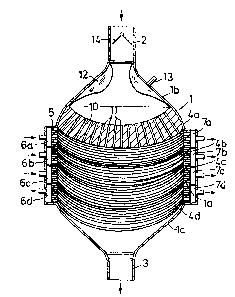
; 30 The exemplifying embodiment of an inventive exchanger
illustrated in Figure 3 has in all essentials the same
basic form as the exchanger illustrated in Figures 1
and 2. The characteristics particular to the exchanger
of the Figure 3 embodiment reside primarily in the
inclusion of a plurality of capillary fibre bundles
4a, 4b, 4c and 4d, the ends of which are connected to
separate inlet chambers 6a, 6b, 6c, 6d and separate
outlet chambers 7a, 7b, 7c, 7d. Each of the separate
.,. :
,:
.,
., .
~Z80577
fibre bundles ~a, 4b, 4c, 4d can thus be caused to
conduct mutually differen~ fluids in relation to which
different types of exchanges shall be effected with
the fluid flowing directly through the vessel 1. In
this regard, the wall structure and internal diameters
of the fibres in respective bundles 4a-4d are, of course,
adapted to the exchange function assigned to that fibre
bundle through which a designated fluid shall pass. For
example, when an exchanger arrangement of this kind is
used as a blood oxygenator, one fibre bundle can be
used to conduct a fluid effective
to remove carbon dioxide from the blood, a second fibre
bundle can be used to conduct
gas effective to supply oxygen to the blood, and
a third fibre bundle can be used to conduct
e.g. temperature-controlled water, the fibres
of this third bundle having completely sealed or impervious
walls so that solely an exchange of heat will take place
between the water and blood. In the case of blood oxy-
genators there is normally a general desire to be ableto influence the temperature of the throughpassing blood
and to this end known blood oxygenators are used in
conjunction with a separate heat exchanger unit. When
using an exchanger arrangement of this form for blood
dialysis purposes, the fibres of one bundle may be
caused to conduct, for instance, a liquid which is
effective to produce the desired ion-exchange with the
blood, the fibres of a second bundle may be caused to
conduct water through the vessel for the purpose of
- 30 controlling the temperature of the blood, and the
fibres of a third fibre bundle may be caused to conduct
through the vessel 1 a liquid which has a pressure
'~ different to that of the pressure of the blood present
in the vessel so as to obtain desired filtration of the
blood, i.e. a liquid reduction. It will be understood
that many various fibre-bundle combinations and fluids
conducted therethrough may be used, depending upon the
use for which the exchanger is intended. It will also
,'''
:,~
., ,
,
'~'
:.;
: .
. .
. .
-:~
` ~80S77
be understood that the number of fibre bundles incor-
porated in the exchanger may vary from case to case.
The fibre bundles 4a-4d need not, of course, extend
parallel with one another, bu~ can be orientated advan-
tageously so as to extend through the central part 1a
of the vessel 1 in mutually different directions. This
enables the uniform flow clistribution of the fluid
passing through the vessel to be further improved.
Neither is it necessary for the various fibre bundles
to lie in discrete layers, one upon ~e other, in
accordance with the Figure 3 illustration, but the
fibres of, for instance, two mutually different fibre
bundles may be intermingled with one another in one
and the same layer, in which case the fibres in the two
mutually different fibre bundles will conveniently extend
through the vessel 1 in mutually different directions,
so as to facilitate connection of the various fibres to
their assigned inlet chambers 6 and outlet chambers 7
respecti~ely. A further advantage that is possibly
afforded by such intermixing of mutually different fibres
is that the fibres involved are able to serve as spacers
therebetween, thereby enabling the fluid which passes
directly through the vessel to flow more readily past
the fibres.
The exchanger arrangement of the Figure 3 embodiment also
differs from the embodiment illustrated in Figures 1 and
2 in that the flow distributing body 10 of the Figure 3
embodiment ls somewhat smaller and takes up only a part
of the vessel inlet part 1b. This enables an elastic,
~,~inflatable bladder 12 to be arranged in the inlet part
1b of the vessel.
In the illustrated embodiment, the inflatable bladder
x ~35 has the form of an annulus which encircles the orifice
of the tubular inlet 2 and to which a varying gas or
liquid pressure can be applied periodically, through a
connector 13, so that the bladder 12 can be periodically
,.~
,.,
:,, ,, - - . - . . . ..
f~ ~
,.. ~ . .
",
. i,. .
- ~2805;r7
inflated and deflated. When there is provided, at the
same time, a suitably constructed and arranged check
valve for preventing back--flow of the fluid flowing
directly through the vessel 1, such as the check valve
14, the periodically inflated and deflated bladder 12
will function as a pump which is both simple and effec-
tive and which will drive the fluid through the vessel
1 from the tubular inlet 2 to the tubular outlet 3
thereof. Such a pumping facility is highly beneficial,
especially when the exchanger is used for blood treat-
ment purposes. The inflatable elastic bladder may, of
course, have other forms than that illustrated by way
of example in Figure 3.
~ pumping facility for pumping the fluid flowing directly
through the vessel 1 can also be obtained by composing
one of the fibre bundles from fibres, or extremely fine-
bore tubes, which have impervious or sealed resilient
walls and by passing through said fibres, or tubes., a
pulsating liquid or gas f].ow, such as to cause the
fibres, or tubes, to expand and contract periodically.
Furthermore, the flow distributing body 10 of the
embodiment according to Figure 1 or 3 may also be hollow,
such as to form a chamber through which the channels 11
extend and through which temperature-controlled water
can be passed for heat exchange with the fluid flowing
through the channels 11.
'rhe exemplifying embodiment illustrated schematically in
Figures 4 and 5 also incorporates a rigid container
or vessel 15, which is connected at one end thereof to
an axially directed tubular inlet 16 and at its other,
opposite end to an axially directed tubular outlet 17, for
one of the fluids between which exchange is to take place.
In this embodiment the vessel 15 has arranged therein
three different bundles 18a, 18b, 18c of capillary fibres
which are positioned so as to surround a centrally
""~
,,
~,
,
.
:
, .,
'~'.'
lZ80~77
g
located and axially extending space 19 in the interior
of the vessel, this space forming an extension of
the tubular inlet 16. It is proposed in respect of this
embodiment that the fibre bundles 18a-18c are supported
by means of a grid or net structure 20 which encircles
the space 19 and around which the fibre bundles are
spread in a manner to surround the space 19 concentri-
cally therewith, as illustrated schematically in Figure
5. The ends of respective fibre bunales 18a-18c are
drawn through and sealed .in the lower, preferably conical
end wall 23 of the vessel 15, in a manner similar to
that described with reference to Figures 1, 2, so that
the ends of the fibre bundles open into associated inlet
chambers 21a, 21b, 21c and outlet chambers 22a, 22b, 22c
located externally of the wall 23. An advantage is
afforded when the fibre bundles 18a-18c are laid heli-
cally around the central, axial space 19, as illustrated
schematically in broken lines 27 in Figure 4.
It will be seen that the fluid entering through the
tubular inlet 16 will pass transversally through the
fibre bundles 18a-18c, between respective fibres, in a
direction substantially perpendicular to the longitudi-
nal axis of the fibres, whereafter the fluid is collec-
ted externally of the outermost fibre bundle 18c andleaves the vessel 15 through the tubular outlet 17.
. One important advantage afforded by the embodiment
illustrated in Figures 4 and 5 is that the fibre
: bundles will have a significant length extension within
the vessel 15, therewith enhancing the effectiveness
of the exchange function.
/
: In order to ensure that the flow distribution transver-
sally of the fibre bundles 18a-18c is as uniform as
posslble over the whole length of the fibre bundles,
a separate pump arrangement for the fluid flowing through
the vessel 15 is located in the central, axial space 19.
; In the illustrated embodimsnt this pump arrangement
,~ ,
, ,
~"
.
~280~77
1 0
comprises an axial tube 24, which extends up through
the central space 19 and carries a plurality of elastic,
inflatable bladders 25a, 25b, 25c which surround the
axial tube 24 and communicate with the interior thereof.
The outer end 24a of the tube 24 is connected to a sour-
ce of pressurized gas or pressurized liquid, with which
the bladders 25a-25c are inflated sequentially, beginning
from the bladder 25a, so that ~he fluid entering through
the tubular inlet 16 is pressed past the fibres in the
fibre bundles 18a-18c in a direction towards the tubular
outlet 17. It is presumed in this respect that a suitable
check-valve arrangement 2~ is provided for preventing the
flow of fluid in the opposite direction. The bladders
25a-25c can thereafter be deflated, by disconnecting the
tube 24 from the source of pressurized gas or pressuri-
zed liquid and connecting it to an outlet
instead. The bladders 25a-25c will, in this way, be
deflated sequentially, beginning with the bladder 25a.
Alternatively, the bladders 25a-25c can be deflated by
interrupting the supply of pressurized gas or pressuri-
zed liquid to the tube 24 and opening, at the same time,
a narrower ventilating or exhausting tube 28 located
coaxially within the tube 24. In this case the bladders
25a-25c will be deflated sequentially with a start from
the bladder 25c.
It will be understood that an exchanger embodiment
; according to Figures 4,5 may also be used with solely
one fibre bundle, and also with a plurality of fibre
bundles, the nature and use of which can be adapted to
the prevailing requirement, in a similar manner to that
~ described with reference to Figure 3. Thus, one of the
-; fibre bundles incorporated in the exchanger illustrated
t' ' ~ in Figures 4,5 can be used for heat exchanging purposes
s~ 35 with the fluid flowing through the vessel 15, or for
' pumping this fluid through the vessel.
, .
,,v If so desired the temperature of the fluid flowing through
t '`
J'~'
~' ';
'''
'~.
,,
'',
'S '
'/
.~ ,
~80~;77
1 1
the vessel 15 can be controlled by arranging an outer
jacket 29 around the vessel 15, as illustrated in Figures
4,5, this jacket being provided with an inlet 30 and an
outlet 31, so as to allow a temperature-controlled liquid
to flow through the space defined between the vessel and
jacket so as to effect an exchange of heat with the fluid
located within the vessel 15 through the wall of said
vessel.
Although it has been assumed in the aforegoing that when
using one of the aforedescribed embodiments of an inven-
tive exchanger for treating blood that the blood is
passed through the rigid container and thus flows between
the capillary fibres, it will be understood that there
is nothing to prevent the blood from being conducted
through one of the fibre bundles when using an exchanger
constructed in accordance with the invention. In this
case, however, the resistance to flow will be greater
and therewith a greater pressure drop in the blood flow.
It will be seen in other respects that many mutually
different embodiments of and modifications to an exchan-
ger constructed in accordance with the invention are
conceivable within the scope of the invention.
":
,:
.
.
..:
..,:
.,~ .
;;,
.
, ....................................... .