Sélection de la langue

Search

Sommaire du brevet 1280651 

Énoncé de désistement de responsabilité concernant l'information provenant de tiers

Une partie des informations de ce site Web a été fournie par des sources externes. Le gouvernement du Canada n'assume aucune responsabilité concernant la précision, l'actualité ou la fiabilité des informations fournies par les sources externes. Les utilisateurs qui désirent employer cette information devraient consulter directement la source des informations. Le contenu fourni par les sources externes n'est pas assujetti aux exigences sur les langues officielles, la protection des renseignements personnels et l'accessibilité.

Disponibilité de l'Abrégé et des Revendications

L'apparition de différences dans le texte et l'image des Revendications et de l'Abrégé dépend du moment auquel le document est publié. Les textes des Revendications et de l'Abrégé sont affichés :

  • lorsque la demande peut être examinée par le public;
  • lorsque le brevet est émis (délivrance).
(12) Brevet: (11) CA 1280651
(21) Numéro de la demande: 1280651
(54) Titre français: MOTEUR A COMBUSTION, PLUS PARTICULIEREMENT MOTEUR A QUATRE TEMPS AVEC ALLUMAGE
(54) Titre anglais: COMBUSTION ENGINE, PARTICULARLY IGNITED FOUR STROKE ENGINE
Statut: Périmé et au-delà du délai pour l’annulation
Données bibliographiques
(51) Classification internationale des brevets (CIB):
  • F02B 31/00 (2006.01)
  • F02B 1/04 (2006.01)
  • F02B 23/08 (2006.01)
  • F02B 75/02 (2006.01)
(72) Inventeurs :
  • CLOKE, MARTIN (Allemagne)
  • HORTON, MICHAEL (Allemagne)
  • MENNE, RUDOLF (Allemagne)
  • STWIOROK, ANDREAS (Allemagne)
(73) Titulaires :
  • FORD MOTOR COMPANY OF CANADA, LIMITED
(71) Demandeurs :
  • FORD MOTOR COMPANY OF CANADA, LIMITED (Canada)
(74) Agent: MARKS & CLERK
(74) Co-agent:
(45) Délivré: 1991-02-26
(22) Date de dépôt: 1986-12-04
Licence disponible: S.O.
Cédé au domaine public: S.O.
(25) Langue des documents déposés: Anglais

Traité de coopération en matière de brevets (PCT): Non

(30) Données de priorité de la demande:
Numéro de la demande Pays / territoire Date
P3542965.8 (Allemagne) 1985-12-05

Abrégés

Abrégé anglais


ABSTRACT
A mixture-compressing spark-ignited four-stroke
internal combustion engine having a combustion chamber
bounded by the piston and the cylinder head, and inlet
and exhaust valves, the valve openings of which are off-
set in plan view in the longitudinal direction of the
engine with respect to a transverse plane of the cylinder
and the valve stems of which form an acute angle when
projected onto the transverse plane of the cylinder, and
a squish area opposite a spark plug and parts of the
inlet valve opening being mashed and supplied with a
mixture by a swirl inlet passage, the swirl inlet passage
supplying a mixture to the inlet valve opening tangenti-
ally, a spark plug being disposed closed to the center of
the cylinder on the side facing the inlet valve opening,
a squish area being provided opposite the spark plug
amounting to between 5% and 15% of the cylinder cross-
sectional area, and the inlet valve opening being masked
on its flow downstream area toward the outer periphery of
the cylinder by a downward projection from the top of the
combustion chamber through the angle of between 70° and
180° at a height of between 70% and 100% of the valve
stroke over a gap width of between 1 and 1.5 mm.

Revendications

Note : Les revendications sont présentées dans la langue officielle dans laquelle elles ont été soumises.


The embodiments of the invention in which an
exclusive property or privilege is claimed are defined
as follows:
1. A mixture-compressing spark-ignited four
stroke internal combustion engine having a combustion
chamber bounded by a piston and a cylinder head, and
inlet and exhaust valves, the valve openings being
offset from the centerline of the bore in plan view in
the longitudinal direction of the engine with respect to
a transverse plane of the cylinder, and valve stems
angled at an acute angle with respect to each other when
projected onto the transverse plane of the cylinder, the
engine including a spark plug and means projecting into
the combustion chamber providing a squish area opposite
the spark plug, and means providing a partially masked
inlet valve opening connected to a swirl inlet passage,
characterized in
the swirl inlet passage being so constructed
and arranged as to pass any fluid therein therethrough
tangentially into the inlet valve opening, the spark
plug being disposed close to the center of the cylinder
on the side of the bore centerline adjacent to and
facing the inlet valve opening, the squish area
opposite the spark plug being in the range of between 5%
and 15% of the cylinder cross-sectional area, and means
projecting downwardly from the top of the combustion
chamber and from the downstream flow area of the inlet
valve opening towards the outer periphery of the
cylinder bore through a circumferential angle of between
70° and 180° at a height of between 70% and 100% of the
total valve stroke and over a gap width of between 1 and
1.5 mm between the projecting means and the piston.

2. An internal combustion engine according to
Claim 1, characterized in that the inlet valve opening
masked area is provided in its area masked over an angle
of between 70° and 180° with a gap enlargement by
bevelling in a range of between 50° and 180°.

Description

Note : Les descriptions sont présentées dans la langue officielle dans laquelle elles ont été soumises.

ENGINE COMBUSTION C~AMBER CONSTRUCTION
This invention relates to a mixture-
compressing internal combustion engine. More
particularly, it relates to a spark-ignited four-stroke
internal combustion engine having a compact combustion
chamber defined in part by a partially mas~ed swirl
inducing inlet port, a near central plug located on the
inlet valve port side, a squish area opposite the spark
plug, and a V-shaped arrangement of the valves actuated
by twin overhead camshafts.
German Offenlegungsschrift 23 59 058 shows a
combustion chamber for a spark-ignited four-stroke
internal combustion engine in which the inlet and
exhaust valves are arranged in a V-shape, and a squish
area located opposite the spark plug partially masks the
valve openings.
A similar combustion chamber for a spark-
ignited four-stroke internal combustion engine is known
from the German Offenlegungsschrift 25 48 134. In this
case, however, the valves are arranged parallel to one
another.
Another mixture-compressing internal
combustion engine having features similar those set
forth above is that of the German Patent 27 31 086. In
this case, the inlet and exhaust valves are shown so
arranged in the combustion chamber 50 that the valve
openings are offset in plan view in the longitudinal
direction of the engine with respect to a transverse
plane of the cylinder, and the valve stems together form
an acute angle when projected onto the transverse plane
of the cylinder. The inlet valve is arranged parallel
to the cylinder axis and the exhaust valve forms an

~30~;5~
acute angle therewith. This results in the exhaust
valve heing disposed in a valve recess formed in the
cylinder head. The combustion chamber is further
defined by a squish area which masks parts of the inlet
valve opening acted upon by a swirl inlet port, the
squish area being located opposite the spark plug.
The latter arrangement ~akes possible an
expedient actuation of the two valves by way of an
overhead camshaft; however, it also requires the
combustion chamber to be situated markedly to one side
inside the cylinder bore and the piston to have a
recess, which enlarges the combustion chamber.
The object of this invention is to design a
mixture-compressing internal combustion engine, in
particular a spark-ignited four-stroke internal
combustion engine, in such a way that it has a more
compact combustion chamber than the prior art, and one
that has an increased lean-mixture combustibility. In
this connection, as a starting point, a V-shaped
arrangement of the inlet and exhaust valves is provided,
which can be actuated in conventional manner by way of
two overhead camshafts.
A swirl inlet passage is provided that acts
upon the air-fuel mixture to supply it to the inlet
valve opening tangentially. A spark plug is disposed
close to the center of the cylinder on the side facing
the inlet valve opening. A squish area is formed
opposite the spark plug that amounts to between 5 and
15~ of the cylinder cross-sectional area. The inlet
valve opening is masked on its downstream flow area
towards the outer periphery of the cylinder by a portion
of the combustion chamber projecting down from the top.
The masking extends through an angle of between 70 and

6Sl
180 at between 70% and 100% of the valve stroke, with a
gap width (see Figure 5) of between 1 and 1.5 mm between
the piston and cylinder head. As a result of all this,
a stabilization of the inlet swirl imparted to the air-
fuel mixture is achieved in the immediate vicinity ofthe spark plug, and a stable combustion action is
attained with an extremely lean mixture preparation.
The exhaust gas constituents which occur with
this lean-type combustion chamber can be reduced to the
prescribed limits of exhaust gas emission in a
relatively inexpensive way with an unadjusted oxidation
catalyst.
By virtue of the fact that the inlet valve
opening is provided in its area masked over an angle of
between 70 and 180 with a gap enlargement by a bevel
in a range of between 50 and 180, it is possible to
ensure an expedient performance of the lean-type
combustion chamber.
The invention now will be described in greater
detail with reference to an embodiment illustrated in
the enclosed drawings in which:
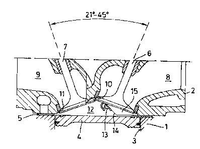
Figure 1 is a vertical sectional view along
the line I-I in Figure 2;
Figure 2 is a diagrammatic plan view of the
combustion chamber according to the invention;
Figure 3 is a sectional view along the line
III-III in Figure 2;
Figure 4 is a sectional view along the line
IV-IV in Figure 2; and

~2~30~51.
Figure 5 is a partial sectional view along the
line V-V in Figure 2.
Figures 1 and 3-5 show vertical partial
sections through the combustion chamber of a cylinder of
a spark-ignited four-stroke internal combustion engine.
It includes a cylinder head 2 mounted on a cylinder
block 1 with the interposition of a conventional
cylinder head seal 5. A cylinder bore 3, in which a
piston 4 is arranged to reciprocate vertically, is
formed in the cylinder block 1.
The cylinder head 2 includes inlet and exhaust
passages 8 and 9, respectively, controlled by inlet and
exhaust valves 6 and 7, respectively. The inlet and
exhaust passages 8 and 9 are connected by inlet and
exhaust valve ports 10 and 11, respectively, opening
into the combustion chamber 12. The latter closes or
terminates the cylinder 3 at the top. A spark plug 13
projects into the combustion chamber 12.
As shown in Figure 1, the stems of valves 6
and 7 are arranged inclined with respect to one another
when projected onto a transverse plane Q (see Figure 2)
of the cylinder in such a way that they form an acute
angle of between 21 and 45, for example. The valves 6
and 7 can be actuated in a manner not shown, but known
per se, by way of two overhead camshafts, for example.
Alternatively, they can be actuated by way of a single
overhead camshaft through suitable rocker arms.
As shown in Figure 2, the inlet and exhaust
valves 6 and 7 are arranged in such a way that when seen
in plan view they are offset in the longitudinal
direction of the engine with respect to the transverse
plane Q of the cylinder. The spark plug 13 in this case

~8()65~
is disposed on the side of the bore axis adjacent to the
inlet valve 6 in a wall portion 14 (see Figures 1 and 3)
that projects down from the top of the combustion
chamber 12, in order to bring the spark gap as close as
possible to the center of the cylinder.
The downwardly projected wall portion 14
continues circumferentially as depression 15 (see
Figures 1, 2, 4 and 5) to embrace or partially surround
(see Figure 2) the inlet valve opening 10 in the
downstream flow area through an angle of between 70 and
180. In this connection, the depression 15 also
extends into the combustion chamber 12 for a depth of
height (see Figures 1, 4 and 5) of between 70~ and 100%
of the total valve stroke, and masks the disc of the
inlet valve 6 with a gap width of between 1 and 1.5 mm
between the piston and depression 15 (see Figures 4 and
5), and with a gap enlargement by a bevel in a range of
between 50 and 180.
A squish area 16 (see Figure 2) which amounts
to between approximately 5% and 15% of the total
cylinder cross-sectional area is located diagonally
opposite the spark plug 13.
With the arrangement shown in Figure 2, the
swirl inlet passage 8 causes the air-fuel mixture to
flow through the inlet valve opening lO tangentially.
The masked portion or depression 15 stabilizes the
swirling action in the region towards the outer
periphery of the cylinder such that a stable swirling
action is maintained in the vicinity of the spark plug
13. Therefore, even lean air-fuel ratios with a of
1.6 can be reliably ignited and burned.

æ~o~s~
This invention has been illustrated in
connection with a single cylinder. However, it should
be pointed out that in the case of a four-cylinder
engine, the combustion chambers can be provided
alternately in a mirror-inverted arrangement, for
example, in which case the swirl produced by the swirl
inlet port and the tangential action upon the inlet
valve opening would not rotate in the counter-clockwise
direction, as shown in Figure 2, but in the clockwise
direction.
While the invention has been shown and
described in its preferred embodiment, it is clear to
those skilled in the arts to which it pertains that many
changes and modifications may be made thereto without
departing from the scope of the invention.

Dessin représentatif
Une figure unique qui représente un dessin illustrant l'invention.
États administratifs

2024-08-01 : Dans le cadre de la transition vers les Brevets de nouvelle génération (BNG), la base de données sur les brevets canadiens (BDBC) contient désormais un Historique d'événement plus détaillé, qui reproduit le Journal des événements de notre nouvelle solution interne.

Veuillez noter que les événements débutant par « Inactive : » se réfèrent à des événements qui ne sont plus utilisés dans notre nouvelle solution interne.

Pour une meilleure compréhension de l'état de la demande ou brevet qui figure sur cette page, la rubrique Mise en garde , et les descriptions de Brevet , Historique d'événement , Taxes périodiques et Historique des paiements devraient être consultées.

Historique d'événement

Description Date
Inactive : CIB de MCD 2006-03-11
Inactive : Demande ad hoc documentée 1994-02-26
Le délai pour l'annulation est expiré 1993-08-31
Lettre envoyée 1993-02-26
Accordé par délivrance 1991-02-26

Historique d'abandonnement

Il n'y a pas d'historique d'abandonnement

Titulaires au dossier

Les titulaires actuels et antérieures au dossier sont affichés en ordre alphabétique.

Titulaires actuels au dossier
FORD MOTOR COMPANY OF CANADA, LIMITED
Titulaires antérieures au dossier
ANDREAS STWIOROK
MARTIN CLOKE
MICHAEL HORTON
RUDOLF MENNE
Les propriétaires antérieurs qui ne figurent pas dans la liste des « Propriétaires au dossier » apparaîtront dans d'autres documents au dossier.
Documents

Pour visionner les fichiers sélectionnés, entrer le code reCAPTCHA :


Pour visualiser une image, cliquer sur un lien dans la colonne description du document. Pour télécharger l'image (les images), cliquer l'une ou plusieurs cases à cocher dans la première colonne et ensuite cliquer sur le bouton "Télécharger sélection en format PDF (archive Zip)" ou le bouton "Télécharger sélection (en un fichier PDF fusionné)".

Liste des documents de brevet publiés et non publiés sur la BDBC .

Si vous avez des difficultés à accéder au contenu, veuillez communiquer avec le Centre de services à la clientèle au 1-866-997-1936, ou envoyer un courriel au Centre de service à la clientèle de l'OPIC.


Description du
Document 
Date
(aaaa-mm-jj) 
Nombre de pages   Taille de l'image (Ko) 
Abrégé 1993-10-19 1 23
Page couverture 1993-10-19 1 16
Revendications 1993-10-19 2 45
Dessins 1993-10-19 2 34
Description 1993-10-19 6 193
Dessin représentatif 2002-01-03 1 13