Note : Les descriptions sont présentées dans la langue officielle dans laquelle elles ont été soumises.
This invention is in the ield of carbon
black. More specifically, -this invention ^relates to
the production of a homogeneous mixture of varlous
typès of carbon black to promote a constant rate of
flow of carbon black into a pelletizer.
High temperature, incomplete combustion of
a hydrocarbon such as petroleum, natural gas and
other well known materials produces carbon black.
When separated from the reaction gases, the product
is a fluffy, carbon black powder.
In a typical furnace process for the pro-
duction of carbon black, a fuel, an oxidant such as
air, and a feedstock are reacted to provide a hot
stream of combustion gases containing carbon black
therein. The combustion gas stream is then quenched
to a lower temperature by means of a water spray. The
black is separated-from the stream of gases in which
it is suspended by known techniques, such as by cyc-
lones and filters, and then conveyed to a pelletizer
and subsequently dried.
Often, a short-term storage tank, called a
surge tank, is locatèd between the collection equip-
ment and the pelletizing equipment to aid in pro-
viding a steady feed of carbon black to the pel-
letizer., A typical tank has a heigh-t of 10-15', the
upper portion of said tank being cylindrical with a
diameter of about 9'. The height of the cylindrical
portion of the tank is approximately 3/4 oE -the total
heigh-t of the tank. The lower remaining portion of
the tank is in the form of a truncated cone, with a
diameter decreasing from 9' at the top-most portion
of the cone to between ~.5-6' at the flat bottom
of the tank. The carbon black, which may be in
the form of dry powder, mois-t powder and/or re-
processed pellets, enters at the top of the -tank and
-- 1 --
'
~Z8~ 5
is emitted through outlets at the bottom of the tank
into one or more pelletizers where the carbon black
is formed into pellets.
Carbon black can be formed into pellets
by the well-known technique of wet-pelletization.
Wet-pelletization is a process whereby carbon black
material is formed into beads or pellets of increased
density, cohesive strength and nondusting charac-
teristics. In -this process, carbon black is wetted,
usually with water, and agitated in a conventional
pelletizer. One of the major control problems in the
wet-pelletization of carbon black is that of main-
taining a proper balance of the mass flow rates of
pelletizing liquid and carbon black powder that are
injected into the pelletizer so that optimum pellet
moisture content is achieved. It is not difficult to
control the mass flow rate of the pelletizing liquid
since the density of the liquid does not change ap-
preciably. The volumetric rate of carbon black can
also be closely controlled. However, variations in
the density of the carbon black are often significant
and occur frequen-tly. These variations in the density
of the carbon black within the surge tank can cause
-the mass flow rate of the carbon black from the surge
tank to the pelletizer to fluctuate. This fluctuation
in mass flow rate can cause the moisture content in
the resulting carbon black pellets to vary. Many
types of equipment have been used to feed carbon
black powder from the surge tank to the pelletizer
but none have provided a dependable stable mass flow
rate of carbon black from the surge -tank into the
pelletizer.
This invention relates to a process and
apparatus for mixing and agitating various types of
carbon black in a surge tank so as to provide a more
uniform mixture o:f carbon black having a more uniform
-- 2
density. By producing in the surge tank such a mix-
ture of carbon black, a more uniform, stable mass
flow rate of carbon black is supplied to the pel-
letizer.
In general the process entails the follow-
ing operations. Carbon black is stirred on at least
two separate vertical levels of the surge tank. Car-
bon black at the bottorn of the tank is lifted by
lifting means; carbon black is pushed equally away
from the center of the tank toward the outlet(s) at
the bottom of the tank; and caking of carbon black on
the wall of the tank is minimized and cake that may
have formed on the wall is removed by scraping means
which rotate in close proximity to the wall of the
tank.
An apparatus suitable for carrying out this
invention is comprised of the following elements
which are inside the surge tank. The elements are
comprised of stainless steel or any other material of
similarly sufficient strength which will not con-
taminate the carbon black.
1) Horizontal blades are attached to a
vertical ro-tating shaft, said hori-
zontal blades being located on at least
two levels of said vertical shaft, the
lowest being sufficiently close to the
bottom of the tank so that the rotation
of the blades keeps the carbon black at
the bottom of the tank in motion. The
highest horizontal blades are placed at
a level sufficiently low so that they
will not interfere with vertical probes
extending downward from the top of -the
tank for the purpose o measuring the
level of carb~n b1ack in thc tanlc.
.. . .. .
~z~
2) Lifters are attached to the ends of the
horizor,tal blades closest to the bottom
of the tank to lift the carbon black
which is located at the bottom of the
tank, the lifters being pointed in the
direction of movement of the horizon-tal
blades and, preferably, angled verti-
cally at 45 relative to the horizontal
blade.
3) Vertical or helical side scrapers ex-
tend out from and are attached to the
ends of the lowest coaxial horizontal
blades, conform to the shape of the
tank wall, and are attached to cor-
responding ends of the top-most coaxial
horizontal blades, said side scrapers
rotating sufficiently close to the wall
of the tank to remove carbon black cake
that may have formed and/or minimize
carbon black from building up on the
wall of the tank, said scrapers being,
preferably, located within two inches
of the tank wall, the edges of the side
scrapers can.also be beveled in the
direction of movemen-t of the side
scrapers.
~) Impeller vanes shaped in the form of
curves are attached to the vertical
shaft just above the lowest horizontal
blades; the outer ends of the impeller
vanes are supported by and connected to
upright bars, said bars being connec-ted
to the ends of the horizontal blades
located closest to the bottom of the
tank and to the ends of the next higher
set of coaxial horizontal blades; the
~ 4 ~
~Z81)~L5
impeller vanes extend out to the edges
of the tank outlets; each segment of
rotation of the impeller vanes causes
an equal movemen-t of carbon black away
from the center of the tank and toward
the edges of the tank outlets.
The above and other features of the in-
vention including varlous novel details of construc-
tion and combinations of parts will now be more
particularly described with reference to the
accompanying drawings and pointed out in the claims.
It will be understood that the particular surge tank
embodying the invention is shown by way of
illustration~ only and not as a limitation oE the
invention. The principles 'and features of this in-
vention may be employed in' varied and numerous
embodiments without departing from the scope of the
invention.
FIGURE 1 is a frontal elevation, partly in
section, of a surge tank.
FIGURE 2 is a side elevation, partly in
section, of the surge tank shown in Figure 1.
FIGURE 3 is a detail view of a lifter
employed with the surge tank.
FIGURE 4 is a plan view of the mixing
elements oE -the surge tank.
FIGURE 5 is a detail view of an impeller
vane.
The process for mixing and agitating carbon
black in a surge tank is comprised of stirring the
carbon black on at ]east two separate vertical levels
wi-thin the tank the lowest of which being suf-
f,iciently close to the bottom of the tank to maintain
the carbon black located at the bottolll of the tank
equally in motion; lifting the carbon black situated
near the bottom of the tank; moving the carbon black
~:ZB~
away from the center of the tank and towards the tank
outlet~s); and minimizing buildup of carbon black on
the wall of the surge tank and/or removing carbon
black cake from the wall of the tank that may have
already formed.
The carbon black is stirred by any suitable
means such as coaxial horizontal blades which are
attached to a vertical rotating shaft in the surge
tank. The horizontal blades are located on at least
two levels of the tank, the lowest set of coaxial
blades being sufficiently close to the bottom of the
tank so that the rotation of the blades will maintain
the carbon black located at the bottom of the tank in
motion.
The vertical level at which the top-most
horizontal blades can be located is limited by the
depth to which vertical probes, which are placed in a
typical surge tank for measuring levels of carbon
black in the tank, extend downwardly from the top of
the tank. The top-most horizontal blades cannot be
placed at any height that would cause interference
with the probes. These vertical probes are necessary
to monitor the level of carbon black within the surge
tank. Preferably, the top-most set of coaxial
horizontal blades should be located at the upper
level of the bo-ttom third of the surge tank to ensure
thorough stirring of the carbon black mixture im-
mediately prior to entry into the pelletizer.
The carbon black situa-ted near the bottom
of the tank is lifted by llfters which are attached
to the ends of -the horizontal blades closest to the
bottom of the tank. The carbon black is simultaneous-
ly lifted by the lifters and stirre~ by the
horizon-tal blades. The lifters are pointed in the
direction of rotation of the blades.
- 6 -
Caking of carbon black on the wall of the
tank is minimized and carbon black cake that may have
formed is removed by means of side scrapers. The
scrapers are either vertical- or helical, extend out-
wardly and conform to the shape of the tank. The
scrapers are attached to the ends of the coaxial
horizontal blades closest to the bottom of the tank
and to the ends of the highest horizontal blades. The
scrapers extend sufficiently close to the wall of the
tank to remove caking of carbon black from the wall
of the tank that may have formed, and/or minimize
carbon black from caking on the tank wall. The
scrapers should, preferably, be located within two
inches of the tank wall. The edges of the side
scrapers may also be beveled in the direction of
movement of the side scrapers.
Carbon. black is moved equally from the
center of the tank towards the outlet(s) of the tank
by suitable means such as impeller vanes. The
impeller vanes are shaped in the form of curves and
are attached to the vertical rotating shaft just
above the lowest horizontal blades. The vanes are
supported by means of vertical upright bars, the ends
of which are attached to the lowest set of horizontal
blades and to the set of coaxial horizontal blades
which is on the next higher vertical level.
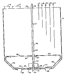
Figure 1 illustrates a stainless steel
surge tank 12 containiny the elements of this in-
ventlon. Carbon black enters the surge tank through
opening 14. Ventilation of -the air in the surge tank
is provided by ven-t 16. Probes 17, 18, 20, 22 and 24
measure the level o carbon black in the surge tank
12. A ro-tating vertical shaf-t 26 is located in the
center of the surge tank. The shaft is comprised of
an inner iron core 27 and an ou-ter stainless steel
jacket 25. The rotating shaf-t is placed through an
opening 28 in the center of the top 30 of the surge
tank and extends down through the center of the tank
through opening 32 in the bottom 34 of the tank 12.
Attached to the rotating shaft 26 are four
sets of coaxial horizontal blades 36, 42, 48 and 54.
The highest set of horizontal blades 36 is comprised
of horizontal bl.ades 38 and 40. Horizontal blades 38
and 40 are attached by means of bolts onto a metal
plate 56 which is welded onto vertical shaft 26.
Horizontal blades 38 and 40 are coaxial and extend
out toward opposite points of the cylindrical wall of
the tank.
The next set of horizontal blades 42 is
positioned approximately midway between the highest
set of horizontal blades 36 and che lower sets of
horizontal blades 48 and 54. Horizontal blades 44 and
46 of set 42 (see Figure 2) are at right angles
rela-tive to the corresponding blades 38 and 40 of set
36. Horizontal blades 44 and 46 are attached by means
of nuts and bolts to metal plate 58, said metal plate
being welded onto vertical rotating shaft 26.
There are two sets of horizontal bla~es 48
and 54 posi-tioned at the same level on the vertical
shaLt 26 near the bo-ttom 34 of surge tank 12. These
sets of horizontal blades 48 and 54 are sufficiently
close to the bottom of the tank so that the rotation
of the blades keeps the carbon black at the bottom of
the -tank in motion. This distance is usually about
one inch from the bottom of the tank. The set of
horizontal blades 54 is parallel to set 42 (see
Figure 2) and the set of bl.ades 48 is parallel to the
highest set of horizontal blades 36. The set oE
horizontal blades 48 is comprised of two blades 50
and 52 which are attached by means of nuts and bolts
onto plate 62 which is wel.ded onto rotating vertical
shaft 26. Horizontal blades 50 and 52 extend out
~.z~307~;
toward opposite points of the wall of tank 12. The
set of horizontal blades 54 (see Figure 2) is
comprised of blades 64 and 66 attached by means of
nuts and bolts to plate 68 which is welded onto
vertical shaft 26. Horizontal blades 64 and 66 extend
toward opposite points along the wall of the tank.
Figure 3 illustrates a lifter attached to a
horizontal blade. A stainless steel bar 72 is welded
onto -the end of the horizontal blade 69. Lifter 7~ is
then welded upwardly at a 45 angle relative to the
horizontal blade onto both the top surface of the
horizontal blade and onto the edge of bar 72. Lifter
74 is pointed vertically in the direction of movement
of the horizontal blade.
Welded to the end of horizontal blade 50 in
Figure 1 is side scraper 76 which extends out and
conforms to the contour of the wa].l of -the tank. Side
scraper 76 extends up and along the wall of the tank
and makes a 90 bend immediately below horizontal
blade 38. The end of side scraper 76 is attached to
the end of horizontal blade 38 by means of nuts and
bolts. Side scraper 76 is sufficiently close to the
wall of the tank to remove caking of carbon black
that may have formed on the wall of the tank, and/or
minimize carbon black from caking on the wall of tank
1.2. In this case, scraper 76 is located within two
inches of -the wall of the tank. In a similar manner,
side scraper 78 extends out and is welded onto the
end of horizontal blade 52. Side scraper 78 makes a
90 bend toward vertical shaft 26 immediately beneath
horizontal blade 40. The end of the scraper is at-
tached -to the end of horizontal blade 40 by means of
nuts and bolts.
In Figure 2, two impeller vanes 82, 84 are
located between the lowest set of horizontal blades
and the next set of horizontal blades 42. The
~B~
impeller vanes are welded onto vertical shaft 26 such
that as vertical shaft 26 rotates, the impeller vanes
rotate in the direction of the convex portion of said
impeller vanes. The impeller vanes (see Figure 4)
extend out from the vertical shaft 26 to the inner
edge of the tank outlets 86 and 88, that is -to the
edge of the tank outlet closes-t to vertical shaft 26.
The impeller vanes are placed in such a manner that
the widths of said vanes are vertical. The end
points 83 and 85 of the convex portion of the
impeller vanes extend to the inner edges 87 and 89 of
the tank outlets.
The impeller vanes are supported at their
ends by vertïcal bars 90, 92 (see Figure 2)~ The ends
of vertical bar 90 are attached to horizontal blades
44 and 64. The end of impeller vane 82 is attached to
and supported by vertical bar 90. The ends of
vertical bar 92 are attached to horizontal blades 46
and 66. The end of impeller vane 84 is attached to
and supported by vertical bar 92.
Figure 5 illustrates one teachnique for
attaching an impeller vane to a vertical support bar.
One end of the vertical support bar 90 is welded onto
the bottom of horizon-tal blade 44 and the other end
of the suppor-t bar 90 is welded onto the top of
horizontal blade 64. Two strips of stainless steel 96
and 98 are welded to the top and bot-tom edges
respectively of the impeller vane 82 at the end of
the impeller vane most distant ~rom the vertical
shaft 26. The s-trips of stainless steel extend toward
vertical support bar 90 and are welded per-
pendicularly onto the side of the bar. Additional
support is provided by a rec-tangular stainless steel
cover 100. Cover 100 ~its tightly within the
rectangular support s-tructure formed by stainless
steel strips 96 and 98 being welded onto the impeller
-- 10 --
vane 82 and vertical support bar 90. The edges of the
cover 100 fit within and are welded to the
rectangular support structure. The cover serves to
prevent the impeller vane from being deformed as the
result of moving carbon black.
Equivalents
Those skilled in the art will recognize or
be able to ascertain, using no more than routine
experimentation, many equivalents to -the specific
embodiments described herein. Such equivaIents are
intended to be covered by the following claims.