Note : Les descriptions sont présentées dans la langue officielle dans laquelle elles ont été soumises.
-
~8~2
01FC 62097
HOSE CONNECTION FOR VACUUM CLEANER ATTACHMENTS
DESCRIPTION
BACKGROUND OF THE INVENTION
Field of thP Invention
This invention relates to hose connected vacuum
cleaner attachments and, more particularly, to a novel
separable connection between a vacuum cleaner hose and
various cleaning attachments.
Description of the Prior Art
Hose .connections such as that disclosed in U.S. No.
1,013,364, January 2, 1912, of Behm are known in the art
in which cleaning attachments are accommodated within a
bore formed in a fitting carried at the free extremity
of a flexible hose. Other hose connections, such as
that dlsclosed in U.S. Patent No. 1,016,649, February 6,
1912, of Spencer are known in whlch cleaning attachments
are formed with a fitting externally encompassing the
free extremity of a bore or wand. None disclose an
arrangement in which the hose or wand may accommodate
z~
attachment fittings either internally or externally; and
none disclose a vacuum cleaner hose or wand having an
attachment retaining latch which is operative to secure
thereon interchangeably either an internally or extern-
ally accommodated attachment fitting.
OB~ECTS OF THE INVENTION
Certain hose or wand supported vacuum cleanerattachments decrease the size of the air passage toward
the free extremity such as is the case with crevice
cleaning tools, small brushes, and the like; and with
such attachments, as well as with attachments in which
the maintenance of small overall size is critically
important, it is advantageous for the attachment to be
accommodated internally of the attachment accommodating
fitting of the flexible hose leading to the vacuum
cleaner. For other types of attachments, wands, and the
like, where it is desirable not to diminish the size of
the air passageway, it is advantageous for the attach-
ment to be accommodated externally of the attachmentaccommodating fitting.
It is an object of the present invention to provide
an attachment accommodating fitting on a conduit leading
to a vacuum cleaner which can accommodate attachments
either externally or internally; and a further object is
to provide a latching device for such an attachment
accommodating fitting which is capable of releasably
securing to such a fitting attachments which are accom-
modated either internally or externally thereon~
~2~az
-2a-
According to a broad aspect, the invention relates
to an attachment accommodating fitting for a vacuum
cleaner air hose including an air hose extremity formed
with an internal cylindrical surface and with an external
cylindrical surface; said internal cylindrical surface
adapted to accommodate therein a small diameter butt on
an attachment, and said external cylindrical surface
adapted to accommodate thereon a large diameter butt on
an attachment; a latch lever pivotally supported on said
air hose; first and second latch finger projections on
one limb of said latch lever, each extending tangentially
with respect to the pivotal support for said latch lever;
said air hose extremity being formed with a latch finger
accommodating aperture; resilient means biasing said
latch lever toward a position in which one of said latch
finger projections traverses said air hose extremity
through said latch finger accommodating aperture; each
small diameter attachment butt being *ormed with a latch
aperture of size and shape corresponding to said first
latch finger projection, and each large diameter
attachment butt being formed with a latch aperture of
size and shape corresponding to said second latch finger
projection; interengaging cam means formed on each
attachment butt and the latch finger projection with
which said attachment butt latch aperture corresponds for
retracting said latch finger projection in opposition to
the bias of said resilient means during insertion of
said attachment butt in place with respect to said hose
extremity until alignment of said latch finger projection
with said latch aperture in said attachment butt is
attained; and operator influenced means for at-will
retracting said latch finger projection to release an
attachment for removal from said hose extremity.
~8~32
DESCRIPTION OF THE DRAWINGS
With the above and additional objects and advant-
ages in view, as will hereinafter appear, this invention
will now be descri~ed with reference to the accompanying
drawings of a preferred embodiment in which:
FIG. 1 is an elevational view partly in vertical
cross section of a hose connection for a vacuum cleaner
in accordance with this invention showing an attachment
accommodated internally of the hose connection and
secured in place thereon;
FIG. 2 is a vertical cross sectional view o~ the
hose connection illustrated in FIG. l, but showing an
attachment accommodated externally of the hose connec-
tion and secured in place thereon; and
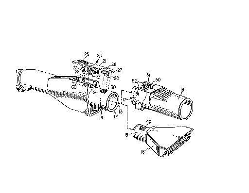
FIG. 3 is a disassembled perspective view of
portions of the hose connection and latch element in
accordance with this invention, together with attach-
ments both internally and externally accommodated on the
hose connection.
Referring to FIG. l of the accompanying drawing, ll
denotes a hand grip portion of an air hose leading to a
- vacuum cleaner (not shown). The cylindrical free
extremity 12 of the hand grip portion of the air hose
has an internal cylindrical surface 13 and an external
cylindrical surface 14.
The free extremity 12 is thus adapted to accommo-
date on the internal surface 13 a small diameter
c~lindrical butt portion 15 of an attachment 16 as
illustrated in FIGS. l and 3, or on the external surface
14 a large diameter cylindrical butt portion 17 of an
attachment 18 as illustrated in FIGS. 2 and 3.
~28~7~
Moreover, this invention provides a latch device
which is simple and cost effective in construction and
assembly which is capable of cooperation in securely
fastening to the hand grip portion of the air hose
attachments accommodated either internally or externally
of the hose extremity. The latch device is provided by
a latch lever 20 which is preferably formed of molded
resilient plastic material. The latch lever includes a
flat substantially straight beam 21 formed substantially
centrally with a depending support blade 2Z which ex-
tends at a slight angle from perpendicularity to the
beam. An angle of 3 from perpendicular has been found
to provide a satisfactory at-rest relationship of the
parts as will hereinafter be described.
Extending from each side of the blade 22 is a bi-
furcated clevis 23 adapted to be forced into embracing
relationship, each clevis with an opposite edge of a
rectangular support aperture 24 formed near the hose
extremity 12.
When thus supported on the hose extremity, the
latch lever 20, because of the angular relationship of
the blade 22 to the beam 21, will position the beam 21
on an inclination to the hose extremity with one beam
extremity of the latch lever which is formed with a
roughened outer surface 25 tilted upwardly and the
opposite beam extremity which is formed with a down-
wardly extending set of latch fingers 26, 27 and 28
tilted downwardly. To this end, the support blade
preferably extends at the aforesaid angle of 87 Erom
that limb of the latch lever beam carrying the latch
fingers 26, 27 and 28.
~z~æ
The two latch fingers 26 and 27 located one at each
side of the beam 21 extend only a short distance from
the beam 21 while the central latch Einger 28 extends
~urther from the beam; and each of the latch fingers is
formed with a sharply inclined free extremity angled
upwardly toward the extremity of the beam 21.
~ latch aperture 30 is formed in the hose extremity
12 with a size and location arranged to align with and
accommodate thersthrough only the central latch finger
28 of the latch lever. The angular disposition of the
blade 22 on the latch lever is such as to urge the latch
lever into a normal position in which the latch finger
28 extends through the latch aperture 30. The latch
fingers 26 and 27 not being accommodated through the
latch aperture 30 limit the extreme position of the
latch finger 28 as shown in FIG. l, and the length of
the latch finger 28 is sufficient to extend through the
latch aperture and within the inside surface 13 of the
hose extremity 12.
Referring to FIGS. l and 3, the butt portion 15 of
each attachment 16 of which the butt portion is oE small
diameter so as to be accommodated in the inside surface
13 of the hose extremity, is formed with a plain rec-
tangular aperture ~0 of similar size and shape to the
latch aperture 30 in the hose extremity.
The extremity of a small diameter butt portion of
an attachment, when inserted into a hose ext,remity
inside surface 13 will serve as a cam means cooperating
with cam means provided by the incllned Eree extremity
of the central latch finger 28 to cam the latch lever in
~21~ 3 D
a counterclockwise direction as shown in the drawings~
upwardly into the latch aperture 30 in the hose extrem-
ity until the latch finger 28 comes into alignment with
the aperture 40 in the attachment butt 15 at which time
the resiliency in the blade element 22 will urge the
latch finger 28 downwardly into securing relationship in
the aperture 40 thus loc~ing the attachment securely in
place.
Referring to FIGS. 2 and 3, the butt 17 for each
attachment 18 which is accommodated externally on the
hose extremity 12 on the outside surface 14 thereof is
formed differently. As shown in FIG. 3, each attachment
butt 17 is formed with a slot 50 extending to the free
extremity of the attachment butt 17. The slot 50 is as
wide as the entire assembly of the latch fingers 26, 27
and 28. From each side of the slot 50 extend shallow
ledges 51, the distance between the ledges 51 being sub-
stantially equal to the width of the central latch
finger 28 with each ledge 51 being tapered toward the
free extremity of the slot as indicated at 52. The
ledges terminate short of the base of ~he slot 50 suf-
ficiently to accommodate through the slot 50 adjacent
the base thereof the entire assembly of latch fingers
26, 27 and 28, as shown in FIG~ 3.
When an attachment with a large diameter butt 17 is
inserted on the hose extremity 12 over the outer surface
14 thereof, the ledges 51 serve as interengaging cam
means cooperating with the cam means provided by the
inclined bottom edges o~ the latch fingers 26 and 27.
The tapered ledge extremities 52 will engage beneath and
- 7
cam upwardly the inclined bottom edges of the latch
fingers 26 and 27 allowing the central latch ~inger to
pass between the ledges 51 until the entire assembly of
latch fingers passes the ledges 51 whereupon the latch
fingers will drop behind the ledges, being urged to do
so by the inclination of the blade 22 on the latch lever
20.
In order to release either an attachment 16 with a
small diamter butt or an attachment 18 with a large
diameter butt ~rom latched relation on the hose
extremity, the vacuum cleaner operator need only depress
the latch lever beam extremity having the roughened
surface 25 to withdraw the latch fingers from whichever
latch aperture in which they may have been engaged so
that the attachment may be removed from the hose
extremity.
A wall 60 may be formed on the hand grip portion of
the hose extremity to encircle and shroud the latch
lever extremity within the roughened surface 25.
Accordingly, there has been disclosed an improved
hose connection for vacuum cleaner attachments. It is
undexstood that the above-described embodiment is merely
illustrative of the application of the princlples of
this invention. Numerous other arrangements may be
devised by those skilled in the art without departing
from the spirit and scope of this invention, as defined
by the appended claims.