Note : Les descriptions sont présentées dans la langue officielle dans laquelle elles ont été soumises.
SINGLE LIME MOORING SYSTEM
TECHNICAL FIELD
This invention relates to offshore terminals for
mooring a vessel, which can be useful for transferring
hydrocarbons or other fluid between an underwater line
and the vessel.
BACKGROUND OF THE INVENTI ON
A variety of offshore terminals have been proposed
for mooring a vessel, especially to enable transferance
of fluids between the vessel and a pipe at the sea floor
or another vessel. One of the simplest and potentially
lowest cost systems includes a transfer structure
10 coupled to the- vessel, a single anchor line extending
down from the transfer structure, and a group of chains
for holding the lower end of the anchor line and
allowing its limited movement as the vessel drifts.
U.S. Patent 3,979,785 describes a system of this type.
15 However, none of such simple systems have been
successfully marketed. One problem has been tha~ while
the use o~ loose chains to hold the bottom of an anchor
line minimizes the amount of chain, especially in deep
waters, the reduced amount of chain results-in only a
20 low restoring Eorce, urging the drifting vessel back
towards the quiescent position of the system. Another
problem is that the long vertical anchor line can be
twisted as a ship drifts around the anchor line. Yet
another problem is tha~ it has been difficult to set up
25 the system and test it. ~t has been even more difficult
to re-establish connection to a vessel after the vessel
-1 -
q~
. , . ' ' ' . ' '
', ,
: ': ' . .. . .
.: ' , , `
has sailed away and then returned. A practical single
anchor line mooring system would have considerable
value.
SUMMARY OF THE INVENTION
In accordance with one embodiment of the invention,
5 a mooring system is provided, o the type which includes
a primarily vertical anchor line ex~ending from a
transfer structure near the sea surface to a chain table
which is near the sea floor and which is anchored by
catenary chains, which can be efficiently installed and
10 operated. The system can include a welght included in
or hanging from the chain table, to aid in installation
and to later aid in mooring. The upper end of the
anchor line can be held to a transfer structure platform
which can rotate about a largely vertical axis with
15 respect to another portion of the transfer structure. A
direction sensor, such as a compass, on the platform
senses its rotation and causes energizat.ion of a motor
that rotates the platform to minimize twisting of the
anchor line.
The chains can initially lie on the sea floor, with
pendant lines extending from the free ends of the chains
up to the sea surface where they are held by floats. A
chain table can be installed by attaching it to an end
of the anchor line while the chain table lies primarily
25 near the sea surface~ A winch lowers the anchor line
and chain table, while the chain table is guided in its
decent by the pendant lines. Hose guides, or
conductors, attached to the anchor line, can receive a
hose extending up to the transfer structure, by pulling
30 the end of the hose up through the conductors.
The novel features of the invention are set forth
with particularity in the appended claims. The
invention will be best understood from the ~ollowing
description when read in conjunction with the
35 accompanying drawings.
BRIEF DESC~IPTI~N OF THE DRAWIMGS
... .
Figure 1 is a side elevation view of an installed
mooring system constructed in accordance with one
embodiment of the present invention.
Figure 2 is a side elevation view of ~he system of
5 Figure 1, before its connection to the transfer
structure on the vesselO
Figure 3 is a view similar to that of Figure 2, but
showing the system during its installation.
Figure 4 is a plan viPw of the chain table of
10 Figure 1.
Figure 5 is a view taken on the line 5-5 of Figure
4.
Figure 6 is a more detailed partial perspective
view of the system of Figure 1 during installation.
Figure 7 is a more detailed view of a portion of
the system of Figure 3.
Figure 8 is a right side view of a portion of the
system of Figure 1, shown with a conduit installed
therein.
Figure 9 is a side view of the system of Figure 8,
showing the rest of the conduit.
Figure 10 is a partial perspective view of the
system of Fi~ure 8, showing the manner in which the
conduit is installed.
Figure 11 is a side elevation view of a system
constructed in accordance with another embodiment of the
inventlon.
Figure 12 is a top view of a float conductor of the
system of Figure 11.
Figure 13 is a side elevation view of a system
constructed in accordance with another embodiment of the
invention.
Figure 14 is a view taken on the line 14-14 of
Figure 13.
. ,
. ' . ~ ' :
',
- :
.
. ~ ' ' , ' ' ~
.
:~
.
~2~
Figure 15 is a view taken on the line 15-15 of
Figure 14, but without the holding structure.
Figure 16 is a partial elevation view of a mooring
system constructed in accordance with another embodimant
5 of the invention.
DESCRIPTION OF THE PREFERRED EMBODIMENTS
~ .
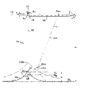
Figure 1 illustrates a mooring system 10 which
includes a transfer structure 12 mounted at the bow end
14 of a vessel 16. An anchor line 18 extends largely
vertically between the txansfer struc~ure which lies
10 near the sea surface 20 and a chain table 22 which lies
closer to thP sea floor 24 than the sea surface. The
chain table lies a distance above the sea floor and is
held by a group of at least three chain devices or
chains 26 that extend in catenary curves to the sea
15 floor. A coun~er weight 28 hangs from the chain table~
When the vessel drifts, so the upper end 30 of the
anchor line at 18A has moved to the position 30A, the
low~r end 32 of the anchor line moves to the position
32A with the chain table at 22A. In so moving, at least
20 one chain device 26 is raised, as by an average distance
R to store potential energy which will urge the vessel
back towards its quiescent position. Since the chain
table at 22 is only a moderate distance above the sea
floor, only a moderate amount of chain is raised as the
25 vessel drifts. It would be possible to use very heavy
chains, but since most o the lengths of chains would
lie on the sea floor, much of the chain weight would not
be used. Applicant's weiyht 28 is raised when the
vessel drifts, to restore the system towards its
30 quiescent position wherein the anchor line 18 is
vertical. The weight 28 is of low cost compared to
chains of the same weight, and all of the weight 28 will
always move and be raised for any direction of the
vessel drift. Thus, the weight provides an efficient
35 means for loading the lower end of the mooring line to
`
:,
' ` '
.
~ ~ .
.
restore a drifting vessel towards its quiescent
position.
The installation of the mooring system can be
conducted easily and with minimal requirements for deep
5 underwater worX. Figure 2 illustrates a system lOC
with the chains 26 having first ends 3~ held to the sea
floor as by an anchor or pile and second ends 36 lying
on the sea ~loor and attached to the lower ends of
pendant lines 38. The upper ends of the pendant lines
lO are held at the sea sur~ace by buoys 39. As shown in
Figure 3, the vessel 16 picks up the buoys and the tops
of the pendant lines and threads them ~hrough
chain-receiving holes in the chain table 22 (~efore it
is lowered). A winch 40 on the transfer structure 12
lS then winches down the chain table 22 until the weight 28
lies at the sea floor. The great decrease in load on
the winch clearly indicates when the weight reaches the
sea floor, and it is then known that the chain table
lies a predetermined distance L above the sea floor.
20 The pendant lines 38 are then pulled upward by a
lightweight winch while the chain ~able 22 remains
stationary, until the second ends 36 o~ the chains enter
the holes Qf the chain table and are then locked to ~he
chain table.
After the ends of the chains are attached to the
chain table, the system must be ~ested by loading it to
its maximum operating load. In prior systems wherein a
transfer structure was anchored by chains extending from
it to the sea floor, this was accomplished by bringing
30 in a barge with a winch, and pulling on each chain
individually to the maximum load. In the present system
applicant uses the same winch 40 (Figure 1) that was
used to lower the chain table, to pull up the chain
table until a maximum operating load has been applied.
35 As shown in Figure 1, the winch pulls up the anchor line
18 until a predetermined tension load is applied to the
.
-
4 ~
top oE the anchor line. The chain ~able ls then at theposition 22B. Through geome~ric calculations, it can be
determined what the load on each of the group of chains
is. The tension on the chains is greater than the
5 upward vertical load on the bottom of the anchor line
18, because the chains extend at leas~ partially in a
horizontal direction. After the test, the chain table
is lowered to the position shown at 22.
Figure 8 illustrates some details of ~he ~ransf2r
structure 12 and other apparatus nearby. The transfer
structure includes a largely non-rotatable platform 44
and a rotatable portion or structure 46 that is mounted
on the bow end 14 of the vessel. The platform is
mounted on bearing 48 ~hat allows it to rotate about a
15 largely vertical axis 50 with respect to the rotatable
structure 460 In ac~uality, the platform 44 undergoes
only limited rotation about the vertical axis, while the
rotatable structure 46 and the vessel can rotate withou~
limit about the vertical axis. A universal joint 52
20 hangs rom the platform, with a hanging lower part 54 of
the joint able to pivot about two horizontal axis 56,
~8. The winch 40 in this embodiment of the invention,
is mounted on the lower part 54 of the joint, to enable
it to pivot so as to minimize bending of the anchor line
25 18 as it enters the winch. The winch 40 is a linear
winch, which includes a stationary uppex pair of jaws 60
and a lower pair of jaws 62 that move up and down. The
mooring line is stored on a reel 64 where the line is
curved but under substantially zero tension. The highly
30 tensioned portion of the anchor line 18, which is the
part lying under the winch, undergoes very little
bending.
During and after installation of the systPm, the
upper end of the anchor line is held by the winch 40.
35 As discussed a~ove, the winch initially lowers the chain
table, then lifts it to test the system, and then lowers
.
.
.
.- ' . '
.
~.~Lf~
it somewhat to the height used for mooring the vessel.
The winch can be operated to change the anchor line
length to change the mooring characteristics. It can be
later used to raise the chain table i the vessel moves
5 away. The same vessel and transfer structure can be
used at different locations of widely different sea
depths, by carrying a sufficient length of anchor line.
A system of the type shown in Figure 1 has been
designed for use in a sea location of a height M of
lO 1,200 feet (366 meters), to moor a storage vessel 16 Gf
65,000 tons (59,000 metric tons) dead weight at 75% of
full load. The hull of ~he vessel then lay at a depth N
of 33 feet (10 meters) below the sea surface, while the
bottom of the transfer structure at the winch 40 lay a
15 height P of 30 feet (9 meters) above the sea surface.
The chain table 22 lay at a helght Q of 180 feet l55
meters) above the sea floor in the ~uiescent condition
of the system, while the bottom of the weight 28 lay a
distance L of 50 feet (15 meters) below the bottom of
20 the chain table. The weight 28 had a height of about 9
feet ~3 meters) and a weight of 360 thousand pounds (163
metric tons). The anchor line 18 was of 5.5 inch (14
centimeters) diameter cable which has a weight of about
pounds per foot (chain can be used instead), while
25 each of the chains 26 was of 3.75 inch (9.5 centimeters)
diameter, grade U-4 chain, and had a length of 2,400
feet (732 meters). The angle T of the top of each chain
in the quiescent condition was about 60 degrees from the
horizontal, and the chain angle, of course, approached
30 zero degrees at locations progressively closer to the
sea floor.
If the vessel 16 of Figure 8 drifts around the
vertical axis 50, the platform 44 does not have ~o
rotate, but can remain substantially stationary to avoid
35 twisting of the anchor line 18. However, considerable
friction in the bearings 48 resist relative rotation of
the platform 44. To avoid twist of the anchor line, a
sensor 66 is provided on the platform to sense the
direction, or orientation about the vertical axis 50, of
the platform. The sensing means or sensor 66 is a
5 compass, gyroscope, radio-wave direction sensor, or
other such direction sensing device. When the sensor 66
detects substantial rotation of the platform, it
controls a motor 70 to rotate the platform in a
direction to counter the rotation to maintain the
10 platform in a largely constant rotational orientation
with respect to the sea floor.
Figures 4 and 5 illustrate details of the chain
table 22. The chain table has three holes 72, 74, and
76 spaced about a central vertical axis 78. A locking
15 mechanism 80 beside each hole includes a latch 82
pivoted at 84 on the frame 86 of the chain table. A
chain can be drawn up through the hole 72 past the latch
82, but when the chain starts to move down, the latch
20 engages it and prevents such downward movement. An
actuator 88 can be operated to release the latch from
the chains to allow the chains to drop away from the
chain table. It may be seen that the chain table has
swivels 90, 92 at its upper and lower ends, the upper
25 swivel connecting to anchor line 18, and the lower
swivel connecting to a flexible chain device 94 that
holds the weight that hangs from the chain table.
As can be seen in Figure 6, the rotatable portion
or structure 46 includes a pair of beams 100, 102 that
30 extend beyond the bow of the vessel to hold bearings
that support the platform 44 so the vertical axis 50
lies beyond the bow. The rotatable structure has a
height of over one meter. The lower portion 104 of the
portion of the transfer structure extending from the
35 vessel is devoid of any cross beam further from the
vessel than the axis 50. This allows the anchor line
indicated at 18D to extend at a considerable angle from
--8--
,
- . :
:' :
.
. , :
- . .
~2~
the vertical as the vessel drifts, without interference
from the transfer structure.
In many applications, a transfer s~ructure 12
(Figure 9) is used not only to moor a vessel, but to aid
5 in transferring fluid such as hydrocarbons between the
vessel 16 and a ~luid conduit 106. The conduit 106 can
extend to a fluid~holding means such as a pipe 108 at
the sea floor, or as indicated at 110 to another vessel
1120 Much of the conduit 106 is in the form of a hose
10 which can bend to accommodate drifting of the vessel.
However, the hose should be stabilized along a dynamic
wave zone 112 which is over 100 feet deep and which may
extend a few hundred feet (e.g., 300 fee~) below the sea
surface 20. Within this zone, waves and other water
15 movements can cause a hose to be repeatedly pushed back
and forth, causing wear, and also causing damage from
hitting against objects such as the vessel or the anchor
line 18. To stabilize the hose, hose-receiving
conductors 114 are spaced along the anchor line 18 along
20 a considerable depth of at least 100 feet. The large
tension in the anchor line 18 allows it to resist
sideward movement, and its holding of the hose
stabilizes the position of the hose near the sea
surface.
Applicant can clamp the conductors 114 at spaced
locations (e.g., every S0 feet) to the anchor line 18 as
the anchor line is lowered by the winch. Alternatively,
applicant can install the conductors after the anchor
line is set up as by an undexwater vehicle. The conduit
30 or hose 106 can be installed by threading it upwardly
through the conductors. One way, indicated in Figure
10, is to attach an end 116 of a threading line 118 to
the end 120 of the hose and to thread the line 118
through the hose--guiding holes 121 of all of the
35 conductors (this can be accomplished before the
conductors are lowered underwater). The line 118 is
' ' ' ~ : -
~: :
~8~
then pulled up to draw the hose up thxough th~conductors. The hose i~ ~hen connected at 122 (Fi~ure
8) to ano~her conduit leadlng ~o a fluid swivel 124 on
thP pla~form, ~o eonnec~ to a pipe 126 leading to the
5 vessel.
Figures 11 and 12 illus~rate another anchor system
130 wherein conduc~ors 132 tha~ are attached to the
anchor line 18, are in the form of ~loats. As shown in
Figure 12, each floa~-conductor 132 includes a portion
10 for clamping to the anchor line 18, a guide portion 134
for guiding and encircling a hose~ and a center portion
136 which is buoyant and forms a float. This has the
advantage that the vessel can sail away from the
terminal loc~ion~ leaving the anchor line only
15 moderately lowered with the weight 28 on the sea floor~
When the vessel returns, it can pick up a float 138
attached to an end 140 of the anchor line. The vessel
can then pick up the upper end of the anchor line at 140
and raise it only a modexate distance ~o again provide a
20 mooring terminal. A hose indicated at 142 and at 143
can remain a~tached to the conductors 132.
-Figures 13-15 illustrate a system which includes a
weight-receiving ~tructure 152 attached to an end of the
vessel, preferably at an underwater location 153 which
25 ~s the most forward underwater location of the vessel
t"forward~' is .the direction away from the vessel
middle~. The weight 154 is held to the structure 152
against movement in every direction but forward, and is
restrained from forward movement by a tying membex 156.
30 The tying member extends from the weight along an upward
rearward incline, with the upper end of the tying member
closer to the middle of the Yessel than the weight.
The weight hangs from the chain table 22 by a chain
device 166 . The chain table 2~ is attached by the
35 anc~or line to a linear winch 158 that lies on the
platfonm 44. Instead of hanging the winch from a
universal joint, a trumpet-shaped fairlead 160 is
--10--
,
.
.
.
', ' , ,, ~ ~
`~ .
provided to ensure at least a moderate radius or
curvature of the anchor line 18 when it is undex large
tension. This arrangement avoids the cost of a
universal swivel, although it results in the anchor line
5 wearin~ out faster. To release the weight, the tying
member 156 is detached from the vessel as by cutting
it. The weight 154 then swings away from the
weight~receiving structure, and it and the chain table
can be lowered. It can be noted in Figure 15 that the
lO weight has a pair of recesses 162 that slideably couple
it to the weight-xeceiving structure 152.
Figure 16 illustrates another system 170 similar to
that of Figure 1, except that the chain table and weight
are combined into a single chain table or energy storage
15 unit 172. The chain table unit 172 can stably rest on
the sea floor, as indicated at 172A, which occurs durïng
installation and later if the vessel moves away. The
unit has a mass and weight of more than 50 tons, to
provide most of the weight which is raised (by height H)
20 when the vessel drifts to shift the unit as to 172B.
The raising of this wei~ht causes it to store potential
energy which is released by pulling the vessel back,
which lowers the unit. At maximum expected drift forces
the anchor line extends anywhere up to a maximum angle A
(Figure 1) of about 30 degrees from the vertical. The
weight of the unit in air is more than 2,000 times the
weight of each foot of anchor line in air, and is filled
with dense material so it has a weight over 1,500 times
the weight of each foot of the anchor line Isteel~ in
30 air or water. Thus, even in very deep seas, of up to
2,000 feet depth, the unit will weigh more than the
anchor line.
The chain table unit 172 weighs more than the
portions of all chains 175, 176, and 177 which lie above
35 the sea floor in the quiescent condition of the system.
In the previous example where the weight 28 of Figure 1
. : '
, ~ ' '
~ 3~ ~
had a weight of 360,000 pounds and the anchor line had a
weight of ahout 65 pounds per foot, the weight had a
mass of about 5,500 times each foot of anchor line. The
weight 172 has a mass of somewhat more than 360,000
5 pounds (e.g., 400,000 pounds) when substituted in Figure
1. Prior art single anchor line systems often used a
chain table without a separate weigh~ and constructed of
perhaps one-quarter inch steel plate, and the chain
~able (and any fluid swivel) was as light in weight as
lO possible, with the weight generally being only a few
tons. In another type of prior art system, a buoy was
included in the chain tableO Applicant purposely uses a
great weight without any buoy portion. In Figure 16,
the unit 172 is filled with material having a specific
15 gravity of well over 3, such as iron ~specific gravity
of 7.9), except for a few holes 174 for passing chains.
The size of the solid weight of about 9 feet height and
12 feet diameter can be compared to a man M of average
height.
Thus, the invention provides a mooring system of
the type which uses a single largely vertical anchor
line whose lower end is anchored by chains to the sea
floor, which enables a practical system to be used. A
weight hanging under the chain table aids in installing
25 it and enhances mooring of a drifting vessel. The upper
end of the anchor line is held by a platform that can
rotate with respect to a vessel. A sensor which senses
turning of the platform controls a motor which rotates
the platform to minimize twisting of the anchor line.
30 hose can be coupled to the transfer structure by
extending the hose through conductors attached to the
anchor line to stablize the hose position near the sea
surface.
Although particular embodiments of the invention
35 have been described and illustrated herein, it is
recognized that modifications and variations may readily
'
, , ' '
. . .
occur to those skilled in the art, and consequentl~, it
is intended that the claims be interpreted to covex such
modifications and equivalents.
.,., ~
, ~ , . . - . .. ~ . . . . . .
' ; i '.: ' . ' ': ''
. .
.... ., . . . :
- . .
.: . . : . . ~ - , , : .
- - . . . .
- : . .. : . . .. .
' ,"',: ' . ,. ' , : '. .
- ~ ~ ~ ,. .. .
- ..
,
~ ' . .
. .: . . : : '