Sélection de la langue

Search

Sommaire du brevet 1281116 

Énoncé de désistement de responsabilité concernant l'information provenant de tiers

Une partie des informations de ce site Web a été fournie par des sources externes. Le gouvernement du Canada n'assume aucune responsabilité concernant la précision, l'actualité ou la fiabilité des informations fournies par les sources externes. Les utilisateurs qui désirent employer cette information devraient consulter directement la source des informations. Le contenu fourni par les sources externes n'est pas assujetti aux exigences sur les langues officielles, la protection des renseignements personnels et l'accessibilité.

Disponibilité de l'Abrégé et des Revendications

L'apparition de différences dans le texte et l'image des Revendications et de l'Abrégé dépend du moment auquel le document est publié. Les textes des Revendications et de l'Abrégé sont affichés :

  • lorsque la demande peut être examinée par le public;
  • lorsque le brevet est émis (délivrance).
(12) Brevet: (11) CA 1281116
(21) Numéro de la demande: 1281116
(54) Titre français: DISPOSITIF SEMICONDUCTEUR POUR LE CONTROLE DES SIGNAUX LUMINEUX ET DES BARRIERES D'UNE VOIE FERROVIAIRE
(54) Titre anglais: SOLID STATE RAILROAD LIGHTS/GATE CONTROLLER
Statut: Durée expirée - après l'octroi
Données bibliographiques
(51) Classification internationale des brevets (CIB):
  • B61L 01/00 (2006.01)
(72) Inventeurs :
  • SNEE, RONALD W. (Etats-Unis d'Amérique)
(73) Titulaires :
  • SAFETRAN SYSTEMS CORPORATION
(71) Demandeurs :
  • SAFETRAN SYSTEMS CORPORATION (Etats-Unis d'Amérique)
(74) Agent: RICHES, MCKENZIE & HERBERT LLP
(74) Co-agent:
(45) Délivré: 1991-03-05
(22) Date de dépôt: 1987-06-25
Licence disponible: S.O.
Cédé au domaine public: S.O.
(25) Langue des documents déposés: Anglais

Traité de coopération en matière de brevets (PCT): Non

(30) Données de priorité de la demande: S.O.

Abrégés

Abrégé anglais


SOLID STATE RAILROAD LIGHTS/GATE CONTROLLER
Abstract of the Disclosure
A railroad crossing lights/gate controller for effecting
operation of the crossing lights and lowering of the crossing gate
during normal train operating conditions and during a gate con-
troller failure mode includes a train sensing input, a gate con-
trol circuit, a lights control circuit, a solid state logic and
monitor circuit and a fail/safe relay. The train sensing input
provides one signal condition when the approach of a train is
sensed and another signal condition when no train is sensed. This
input is connected to the solid state logic and monitor circuit
which is also connected to the gate control circuit and the lights
control circuit. The gate control circuit has power applied
thereto to maintain the gate in a raised position when the train
sensing input indicates a no train condition and the lights con-
trol circuit has power supplied thereto to operate the lights in
a flashing condition when the train sensing input indicates the
approach of a train. The logic and monitor circuit applies and
removes power to the gate and lights control circuits in accord-
ance with the signals at the input. The fail/safe relay is con-
nected to the logic and monitor circuit and to the gate and lights
control circuits to automatically remove power to the gate control
circuit and apply power to operate the lights in the event no pow-
er is applied thereto. The logic and monitor circuit further
senses the application of power to the gate control circuit and
to the lights control circuit and removes power to the fail/safe
relay under certain sensed conditions.

Revendications

Note : Les revendications sont présentées dans la langue officielle dans laquelle elles ont été soumises.


The embodiments of the invention in which an exclusive
property or privilege is claimed are defined as follows:
1. A crossing lights/gate controller for effecting
operation of the crossing lights and lowering of the crossing gate
during normal train operating conditions and during a controller
failure mode including,
a train sensing input providing one signal condition
when the approach of a train is sensed and another signal condi-
tion when no train is sensed,
a gate control circuit which has power supplied thereto
to maintain the gate in a raised position when the train sensing
input indicates a no train condition,
a lights control circuit which has power supplied there-
to to operate the lights in a flashing condition when the train
sensing input indicates the approach of a train,
a solid state logic and monitor circuit connected to
said input, gate control circuit, and lights control circuit, said
logic and monitor circuit applying and removing power to said gate
and lights control circuits in accordance with the signals at said
input,
and a fail/safe relay connected to said logic and mon-
itor circuit and said gate and lights control circuits, which re-
lay automatically removes power to said gate control circuit and
applies power to operate the lights in the event no power is ap-
plied thereto.
2. The controller of claim 1 further characterized in
that said logic and monitor circuit monitors the application of
power to said gate control circuit and said lights control cir-
cuit, said relay automatically removing power to said gate control
circuit and applying power to operate the lights in the event the
logic and monitor circuit has a train sensed input and senses ei-
ther power to the gate control circuit or no power to the lights
control circuit.

3. The controller of claim 2 further characterized in
that said logic and monitor circuit also monitors the rate at
which said lights flash, with the flashing rate, along with the
sensed conditions of power to the gate control circuit or no power
to the lights control circuit, being one of the conditions which
is effective to remove power to said fail/safe relay.
4. The controller of claim 1 further characterized in
that said lights control circuit and gate control circuit each
include relays whose contacts have a normal position in which
power is supplied to maintain the gate in a raised position and
power is supplied to operate the lights in a flashing condition
which relay contacts will move to a contrary position upon the
loss of power at said fail/safe relay.
5. The controller of claim 1 further characterized by
and including a direct connection between said input and said
fail/safe relay.

Description

Note : Les descriptions sont présentées dans la langue officielle dans laquelle elles ont été soumises.

lZ~
Summary of the Invention
~ he present invention relates to controllers for rail-
road grade crossings and in particular to a controller for effect-
ing operation of the crossing lights and lowering oE the crossing
gates, both during nor~al train operating conditions and during a
controller failure ]~ode.
' A primary purpose of the present invention is a crossing
lights/gate controller which has solid state logic and utilizes a
fail/safe or vital relay to insure that under any abnormal condi-
tion the gates will come down and the lights will be powered.
Another purpose is a grade crossing controller of the
type described which is simple in construction and reliably oper-
able.
Another purpose is a crossing lights/gate controller
which includes a fail/safe or vital relay which responds both to
the solid state logic circuit and to a loss of power or other
abnormal condition to insure that the gate will be lowered and
the lights will be powered.
Other purposes will appear in the en~uing specification,
drawing and claims.
Brief_Description of the Drawing
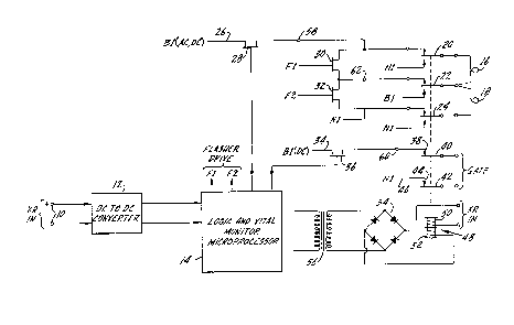
The invention is illustrated in the following block
diagram of the control circuit described herein.
"~
-2-

Description of the Preferred Embodiment
In the railroad industry safety is a paramount concern
and in such areas as railroad signal systems and railroad air
brakes, whenever there is what appears to be a failure, the train
brakes are operated or the si~nal system goes dark, which is an
indication to a train crew of a red or danger condition. Thus,
what can be perceived as a system failure has the effect oE shut-
ting down train operations.
The situation is somewhat diferent at a railroad grade
crossing, as in that situation when there is what can be perceived
as a failure mode, the crossing equipment must be operated. The
gate must come down and the signal lights must be illuminated.
Accordingly, it is necessary to provide a means to automatically
insure that any type of abnormal condition will effectively cause
the lights and the gate to function in a manner so as to warn a
person using the grade crossing.
In the railroad industry certain components have the
term "vital" applied thereto when such components are required to
- never be able to fail, or always to operate in a predetermined
manner in the event of a failure o~ some other part o the system.
In the present invention, a relay has been termed a vital relay
in that whenever certain conditions are brought about in the grade
crossing control, this relay will have its contacts always ~ove
to a certain predetermined position, which position is ef~ective
to cause operation of the gate and illumination of the signal
lights. Such a vital relay is combined in the present inv~ntion
with solid state logic which insures operation of the grade cros-
sing equipment in the normal manner and also insures that the ~i-
tal relay will ~unction in the appropriate manner in an emergency
3~ situation. `
In the drawing, an input is indicated at 10 and will be
the input signal from themotion sensing circuit which is used at
grade crossings to detect the presence of an approaching train

and thereby cause operation of the gates and lights. U. S. Patent
3,944,173, assigned to the assignee of the present application,
illustrates a railroad crossing motion detector of the type which
may be used to provide an input at terminals 10. Terminals 10 are
connected to a DC-to-DC converter 12 which converts the voltage
level at terminals 10 to a level more appropriate for the log~c
circuit to be described. The normal input to ter~inals 10 will be
a signal at a predetermined voltage level when there is no train
approaching or present. When a ~rain has been sensed, the custom-
ary output from a motion detector is no input at terminals 10 andthe lack of a signal is known to indicate that the crossing appa-
ratus should be operated.
A logic and vital monitor microprocessor is indicated at
14 and is connected to converter 1~ and thus receives an input of
the signal indicating the presence or absence of a train at the
crossing. Logic circuit 14 will have programmed firmware to per-
form the functions described below.
Warning lights are indicated at 16 and lB, with these
lights representing the plurality of lights which are normally
present at every grade crossing. Light 16 is connected to a relay
contact arm 20 and a relay contact arm 22. Light 18 is connected
to relay contact arm 22 and to a relay contact arm 24. ~ach of
contact arms 20-24 are movable between upper and lower contacts,
with the normal position of the relays being for the arms to be
in contact with the upper contacts.
A source of either AC or DC power is applied to a ter-
minal 26 which is connected to a switch 28, the position of which
is controlled by logic circuit 14. The other side of switch 28 is
connected to the upper co'ntact for contact arm 200 Flasher drive
switches 30 and 32`are conn~cted across the three sets of relay
contacts which cooperate with contact arms 20-24 to cause opera
tion of the lights. The flashers cause the well~known flashing
or periodic application of power to lights 16 and 18. The lower
--4--

contact of each of the above-described pairs of contacts are con-
nected to voltage or power sources designated N1, B1 and N1, re-
spectively, with terminal 26 having polarity B1. If the signal
lights are operated by AC power, the terminals designate the hot
side of the line and ground, whereas, if DC power is being ap-
plied, the terminals will be positive and negative.
The control for flashers F1 and F2 is indicated to come
from loyic circuit 14 where the flasher drive outputs are indicat-
ed.
A crossing gate is normally maintained in the up or
raised position by the application of power. Thus, DC power from
terminal 34 is applied ~o a normally closed switch 36 to apply
power to a contact 38 which cooperates with contact arm 40 to
apply DC power to the gate drive to main~ain it in an up position.
Contact arm 42, also a part of the gate power supply circuit is
in contact with a contact 44 connected to power supply terminal
46. Thus, there is a closed circuit from positive to negative
through the described relay contacts and relay contact arms which
will maintain the gate in an up position as long as switch 36 is
closed.
The vital relay is indicated at 48 and may have two
relay coils, an upper coil indicated at 50, having a direct con
nection to input 10, and a lower coil 52 connected to a bridge
rectifier 54 and through a transformer 56 to logic circui~ 14.
Power to either of coils 50 or 52 will maintain contact arms 20,
22, 24, 40 and 42 in the position shown. Under normal operating
conditions, power will be supplied to coil 52 by logic circuit
14.
Although not shown, the power supply will include both
AC and DC sources and more particularly a back-up DC battery which
is at every grade crossing and it utilized to provide assurance
that the crossing system will operate in the event of a local
power failure.
-5

~2~
Under normal operating conditions, the gate control
circuit and the lights control circuit have their relay contacts
in the position shown. As long as a signal is present at input
terminal 10, logic circuit 14 will maintain switch 28 ln the open
position and switch 36 in the closed position. Thus, power is
supplied to the gate to maintain it in a raised position and no
power is supplied to the warning lights. In the event a train is
sensed on the section of track adjacent to the ~rade crossing,
there will be a loss of signal at input 10, which loss of signal
will cause the logic and vital monitor microprocessor to close
switch 28 and open switch 36. The flasher drive will also be
activated. The closing of switch 28 will apply power to illumi-
nate the lights and the flashers will simultaneously function to
provide the well known flashing light condition. The removal of
power by the opening of switch 36 will cause the gate to be lower-
ed as it is maintained in a raised position by the application of
power.
There are three circuit condition sensors which are mon-
itored by logic circuit 14~ Sensor 58 monitors the application
o~ power to the lights. Sensor 60 monitors the application of
power to the gate circuit and sensor 62 monitors the rate at whlch
the flashers function. At such time as t~ere is a loss of signal
at terminals 10, the gate and lights will function in the manner
described, providing that each of sensors 58, 60 and 62 indicate
that power is applied to the lights, power is not applied to the
gate, and the flashers are functioning in a normal manner. ~n the
event that any one of the three described sensors gives an indica-
tion which is not appropriate for a train present input signal to
the logic circuit from terminals 10, the logic circuit will remove
power from transformer 56 and thus from coil 52 of vital relay 48.
Since there is no power to coil 50l contact arms 20, 22, 249 40
and 42 will each move to a position opposite that shown in the
drawing. Automatically, when any malfunction is detected by any
--6--

any one of the three sensors, the vital relay will operate. Sim-
ilarly, if there is a loss of power in the logic circuit, the vi-
tal relay will function, assuming no signal at input 10, which
will cause all of the contact arms controlled by coils 50 and 52
to move to a a position opposite that shown in the ~rawings. The
vital relay is either so mechanically positioned or khe contact
arms have spring contro~ such that in the event oE a loss of power
to coils 50 and 52, the contact arms automatically will move away
from the position shown.
When contact arms 20, 22 and 24 all move to a down posi-
tion, lights 16 and 18 will be connected directly to the power
supply represented by terminals N1 and B1. The lights will be
illu~inated, although they will not be flashed, as the flashers
are not in the circuit when the contact arms are in the down posi-
tion. Thus, there will be continuous illumination o~ the lights
at the grade crossing.
In like manner, when contact arms 40 and 42 move away
from contacts 38 and 44, respectively, power is removed from the
gate circuit which causes the gate to be lowered.
The direct connection between input ~0 and coil 50 of
vital relay 48 provides a reliability enhancement to insure that
the vital relay is responsive to a signal at the input and is not
misled by a loss of power from the vital relay. The vital relay
is used to turn on the lights and to lower the gate when something
is wrong in the system, regardless of what it may be. There may
be a power failure, or there ma~ be a failure in the logic circuit
or there may be some other type of malfunctionO When something
does go wrong, because of the nature of the rela~l the gate is
lowered and the lights are turned on.
Whereas the preferred form of the invention has been
shown and described herein, it should be realized that there ma~
be many modi~ications, substitutions and alterations thereto.

Dessin représentatif
Une figure unique qui représente un dessin illustrant l'invention.
États administratifs

2024-08-01 : Dans le cadre de la transition vers les Brevets de nouvelle génération (BNG), la base de données sur les brevets canadiens (BDBC) contient désormais un Historique d'événement plus détaillé, qui reproduit le Journal des événements de notre nouvelle solution interne.

Veuillez noter que les événements débutant par « Inactive : » se réfèrent à des événements qui ne sont plus utilisés dans notre nouvelle solution interne.

Pour une meilleure compréhension de l'état de la demande ou brevet qui figure sur cette page, la rubrique Mise en garde , et les descriptions de Brevet , Historique d'événement , Taxes périodiques et Historique des paiements devraient être consultées.

Historique d'événement

Description Date
Inactive : Lettre officielle 2009-01-27
Inactive : Périmé (brevet sous l'ancienne loi) date de péremption possible la plus tardive 2008-03-05
Lettre envoyée 2006-08-24
Lettre envoyée 2005-07-21
Lettre envoyée 2004-04-28
Accordé par délivrance 1991-03-05

Historique d'abandonnement

Il n'y a pas d'historique d'abandonnement

Titulaires au dossier

Les titulaires actuels et antérieures au dossier sont affichés en ordre alphabétique.

Titulaires actuels au dossier
SAFETRAN SYSTEMS CORPORATION
Titulaires antérieures au dossier
RONALD W. SNEE
Les propriétaires antérieurs qui ne figurent pas dans la liste des « Propriétaires au dossier » apparaîtront dans d'autres documents au dossier.
Documents

Pour visionner les fichiers sélectionnés, entrer le code reCAPTCHA :


Pour visualiser une image, cliquer sur un lien dans la colonne description du document. Pour télécharger l'image (les images), cliquer l'une ou plusieurs cases à cocher dans la première colonne et ensuite cliquer sur le bouton "Télécharger sélection en format PDF (archive Zip)" ou le bouton "Télécharger sélection (en un fichier PDF fusionné)".

Liste des documents de brevet publiés et non publiés sur la BDBC .

Si vous avez des difficultés à accéder au contenu, veuillez communiquer avec le Centre de services à la clientèle au 1-866-997-1936, ou envoyer un courriel au Centre de service à la clientèle de l'OPIC.


Description du
Document 
Date
(aaaa-mm-jj) 
Nombre de pages   Taille de l'image (Ko) 
Abrégé 1993-10-18 1 38
Revendications 1993-10-18 2 63
Dessins 1993-10-18 1 19
Description 1993-10-18 6 250
Dessin représentatif 2001-11-04 1 11
Taxes 1998-02-16 1 36
Taxes 2000-02-09 1 36
Taxes 2001-02-15 1 35
Taxes 1999-02-17 1 35
Taxes 2002-02-06 1 37
Correspondance 2006-08-23 5 406
Correspondance 2009-01-26 1 21
Taxes 1997-02-24 1 35
Taxes 1996-02-22 1 38
Taxes 1992-11-25 1 32
Taxes 1995-03-02 1 40
Taxes 1994-02-27 1 31