Sélection de la langue

Search

Sommaire du brevet 1281881 

Énoncé de désistement de responsabilité concernant l'information provenant de tiers

Une partie des informations de ce site Web a été fournie par des sources externes. Le gouvernement du Canada n'assume aucune responsabilité concernant la précision, l'actualité ou la fiabilité des informations fournies par les sources externes. Les utilisateurs qui désirent employer cette information devraient consulter directement la source des informations. Le contenu fourni par les sources externes n'est pas assujetti aux exigences sur les langues officielles, la protection des renseignements personnels et l'accessibilité.

Disponibilité de l'Abrégé et des Revendications

L'apparition de différences dans le texte et l'image des Revendications et de l'Abrégé dépend du moment auquel le document est publié. Les textes des Revendications et de l'Abrégé sont affichés :

  • lorsque la demande peut être examinée par le public;
  • lorsque le brevet est émis (délivrance).
(12) Brevet: (11) CA 1281881
(21) Numéro de la demande: 1281881
(54) Titre français: TUILE POUR COUVERTURE
(54) Titre anglais: ROOFING TILE
Statut: Périmé et au-delà du délai pour l’annulation
Données bibliographiques
Abrégés

Abrégé anglais


A B S T R A C T
A roofing tile comprises a rectangular panel
having longitudinal edge portions adapted to extend
in the slope direction of a sloped roof and an upper
lateral edge and a lower lateral edge is adapted to run
parallel to the horizontal edges of the sloped roof. The
upper lateral edge and one longitudinal edge portion has
an upstanding ledge portion. The other longitudinal
edge portion has a raised portion with a downwardly
extending flange. The raised portion is adapted to overlap
the upstanding ledge of the one longitudinal edge portion.
The bottom edge portion has a downwardly extending flange
adapted to overlap the upstanding ledge at the upper edge
portion. A lower portion of the one longitudinal edge
portion is provided with fastener access means whereby
a fastener can be passed therethrough to anchor the tile
to the roof. The lower portion is provided with a recess
defined in the panel inwardly of the upstanding ledge.
The flange of the raised portion on the other longitudinal
edge portion is provided with a tab adapted to tightly
fit within the corresponding recess of an adjacent tile
such that when a fastener anchors the lower one
longitudinal edge, the tab is interlocked within the recess
of the adjacent tile.

Revendications

Note : Les revendications sont présentées dans la langue officielle dans laquelle elles ont été soumises.


The embodiments of the invention in which an exclusive
property or privilege is claimed are defined as follows:
1. A roofing tile comprising a rectangular panel
having longitudinal edge portions adapted to extend
in the slope direction of a sloped roof and an upper
lateral edge and a lower lateral edge adapted to run
parallel to the horizontal edges of the sloped roof; the
upper lateral edge and one longitudinal edge portion
having an upstanding ledge portion, the other
longitudinal edge portion having a raised
portion with a downwardly extending flange,
the raised portion being adapted to overlap the upstanding
ledge of the one longitudinal edge portion; the bottom
edge portion having a downwardly extending flange
adapted to overlap the upstanding ledge at the upper
edge portion; a lower portion of said one longitudinal
edge portion being provided with fastener access means
whereby a fastener can be passed therethrough to anchor
the tile to the roof, and said lower portion being
provided with a recess defined in the panel inwardly
of the upstanding ledge; the flange of said raised
portion on said other longitudinal edge portion being
provided with a tab adapted to tightly fit within the
corresponding recess of an adjacent tile such that when
a fastener anchors the lower one longitudinal edge,
the tab is interlocked within the recess of the adjacent
tile.

2. A roofing tile as defined in claim 1 wherein the
tab is at a slight outward angle such that when it
engages the recess, it is in frictional engagement
therewith such that when the one longitudinal edge of
the tile is lowered to be anchored to the roof by
a fastener, the tab is urged outwardly within the
recess against the wall of the recess to interlock
the tab therewith.
3. A roofing tile as defined in claim 2, wherein a
second fastener access means is provided in a diagonally
opposite corner of the tile.
4. A roofing tile as defined in claim 1, wherein
the lower longitudinal edge portion is cut away and is
adapted to receive the upper diagonally opposed corner
of a diagonally adjacent tile.
5. A roofing tile as defined in claim 1, wherein
the other longitudinal edge is provided with a raised
partially cylindrical portion with a flange extending
downward therefrom and adapted to engage the top
surface of the panel inwardly of the upstanding ledge
so formed.
6. A roofing tile as defined in claim 1, wherein
the upstanding ledge is in the form of a continuous
channel extending about the said one longitudinal edge
and the upper lateral edge, the channel being opened
downwardly.

Description

Note : Les descriptions sont présentées dans la langue officielle dans laquelle elles ont été soumises.

~8~383L
The present invention relates to roofing tiles
and in particular, to simulated clay tiles used for
roofing.
The clay tiles which have been commonly used
as a roofing tile for centuries in Europe are attractive,
durable and resistant to most weather conditions.
However, they are heavy, expensive both in terms of
material and installation, and are brittle.
There have been attempts to provide simulated
clay tiles such as described in U.S. patent no. 1,638,755,
Tyra, 1927. This patent illustrates a sheet metal tile
simulating a Spanish tile; U.S. patent no. 4,251,967,
Hoofe III, 1981, describes a molded A.B.S. tile;
U.S. patent no. 4,262,466, Roe, 1981, describes a molded
concrete tile; and U.S. patent no. 4,498,267, Beck, 1985,
describes a laminate of fiberglass reinforced gypsum and
a gelcoat covering the latter layer.
It is important that the roofing tile have a
construction which can easily be installed, provides a
barrier to water seepage and moisture and especially
when constructed of lighter weight, more flexible
materials, can be securely fastened to prevent lifting
due to wind.
It is an aim of the present invention to provide
an improved simulated clay tile which incorporates the
advantages of the above mentioned prior art, that is of
being made of a material which is light, has the required
strength and appearance of the clay tile yet is an
2 --

38~
improvement thereover in the sense that it has an improved
construction which allows the tile to be securely
fastened and provides an improved moisture and water
barrier.
A roofing tile in accordance with the present
invention comprises a rectangular panel having
longitudinal edge portions adapted to extend in the slope
direction of a sloped roof and an upper lateral edge and
a lower lateral edge adapted to run parallel to the
horizontal edges of the sloped roof. The upper lateral
edge and one longitudinal edge portion have an upstanding
ledge portion while the~other longitudinal edge portion is
raised with a downwardly extending flange. The raised
edge portion is adapted to overlap the upstanding ledge
of the one longitudinal edge portion. The bottom edge
portion has a downwardly extending flange adapted to
overlap the upstanding ledge at the upper edge portion.
A lower portion of said one longitudinal edge portion
being provided with fastener access means whereby a
fastener can be passed through to anchor the tile to
the roof; and the said lower portion being provided
with a recess defined inwardly of the upstanding ledge.
The flange of the raised portion on said other
longitudinal edge portion being provided with a tab
adapted to tightly fit within the corresponding recess of
an adjacent tile such that when a fastener anchors the
lower one longitudinal edge, the tab is interlocked
within the recess.
More specifically, the tab is at a slight outward
angle such that when it engages the recess, it is in
frictional engagement therewith and the one longitudinal
edge of the tile is raised from the roof and the one
-- 3

L88~
longitudinal edge is then lowered and the fastener
engaged, tab is urged outwardly within the recess against
a wall of the recess to interlock the tab therein.
Having thus generally described the nature of
the invention, reference will now be made to the
accompanying drawings, showing by way of illustration, a
preferred embodiment thereof, and in which:
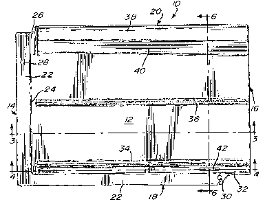
Figure 1 is a top plan view of a tile in accordance
with the present invention;
Figure 2 is a perspective partly exploded view
of tiles in accordance with the present
invention in an assembled position;
Figure 3 is a vertical cross-section taken
along lines 3-3 of Figure l;
Figure 4 is a vertical cross-section taken
along lines 4-4 of Figure l;
Figure 5 is a vertical cross-section taken along
lines 5-5 of Figure 2; and,
Figure 6 is a vertical cross-sectional view of
assembled tiles in the direction of
lines 6-6 shown in Figure 1.
Referring now to the drawings and in particular,
to Figures 1, 3 and 9, there is illustrated a simulated
tile 10, made of molded fiberglass material provided with
a flat thin rectangular panel 12, having a lateral upper
edge portion 14 and a lower lateral edge portion 16.
Longitudinal edge portions 18 and 20 extend between the
lateral edge portions 14 and 16. The lateral edge
portion 14 is provided with a channel shaped upright
ledge 22 having a front wall face 24, i.e., the channel
-- 4

L881
opens towards the bottom as shown in Figures 3 and 4.
The channel shaped ledge 22 extends continuously along
the upper lateral edge 22 and around the longitudinal
edge 18 to terminate near the longitudinal edge 16 at
a cut-out portion 32. Apertures 28 and 30 are provided
on the ledge 22 near diagonal opposed corners of the tile.
These apertures 28 and 30 are provided to receive
fastening means such as nails which pass through the
apertures to anchor the tile 10 into the roof R.
The panel 12 is provided with longitudinally
extending parallel ribs 34 and 36. These ribs provide
ornamentation as well as strength to the panel 12.
The longitudinal edge portion 20 is raised in a
cylinder like portion and is identified by the numeral 38.
The raised portion 38 terminates abruptly at the lower
lateral edge 16 and is spaced from the upper lateral
edge 14, by a groove 26. The raised portion 38 is
provided with a flat surface 40 at a 45 angle to the
panel 12. The raised portion 38 includes a flange 39
! 20 with a tab 46 extending downwardly from the flange 39
as shown in Figures 2 and 6.
The lateral lower edge 16 is provided with
a downwardly extending flange 48 which is adapted to
engage, as will be described, the surface of the panel 12
in front of the wall surface 24 of the outstanding
ledge 22. The panel includes nibs 44 for supporting the
tile powerfully on the roof surface.
A recess 42, as shown in Figures 1 and 4, is
provided between the rib 34 and the raised channel
shaped ledge 22 of the longitudinal edge portion 18.
In this case, the recess 42 is provided just adjacent
the aperture 30 but in the groove formed by the rib 34

8~3~
and the upstanding ledge 22. The tab 46 extends from the
flange 39 at an angle of approximately 6 fro~ the vertical.
The dimensions of the tab 46 correspond to the dimensions
of the recess 42 such as to fit within the recess 42.
The raised portion 38 is adapted to overlap the
upstanding ledge 22 of the longitudinal edge 18 with the
tab 46 engaging within the recess 42 as will be described
further. The tiles lOa through lOe as shown in Figure 2
are assembled in a conventional manner with the lower
lateral edges 16 overlapping the upper lateral edges 14.
The lower portion of the raised portion 38 is provided
with a cut-out 50 adapted to mate within the recess 26
while the flange 48 sits between the ends of ribs 34
and 36 and the front face 24 of the upstanding ledge 22
along the lateral edge 14. The flange 39 of the upstanding
portion 38 likewise overlaps the upstanding ledge 22
of the longitudinal ledge 18.
When the tile 10 is assembled to an adjacent
tile lOa for instance, the tab 46 is first aligned
so that it enters the recess 42 between the rib 44 and
the upstanding ledge 22. The tab 46 is snap-fitted into
the recess 42 and the edge 18 is then pressed down against
the resistance of the angled tab 46 within the recess 42
until it abuts against the surface of the roof and a
fastener 52 is then inserted through the aperture 32 to
anchor that corner of the tile 10 to the roof R. Thus, a
slight torsional force is provided to the tab 46 which
extends at an angle of 6 from the vertical, within the
recess 42 to interlock with the recess 42. Finally,
a fastener 54 is provided in the upper corner through the
aperture 28 to solidly anchor the tile to the roof.

L88~
Subsequent tiles in lateral and vertical rows are then
overlapped and laid thereon in the manner described.
-- 7

Dessin représentatif
Une figure unique qui représente un dessin illustrant l'invention.
États administratifs

2024-08-01 : Dans le cadre de la transition vers les Brevets de nouvelle génération (BNG), la base de données sur les brevets canadiens (BDBC) contient désormais un Historique d'événement plus détaillé, qui reproduit le Journal des événements de notre nouvelle solution interne.

Veuillez noter que les événements débutant par « Inactive : » se réfèrent à des événements qui ne sont plus utilisés dans notre nouvelle solution interne.

Pour une meilleure compréhension de l'état de la demande ou brevet qui figure sur cette page, la rubrique Mise en garde , et les descriptions de Brevet , Historique d'événement , Taxes périodiques et Historique des paiements devraient être consultées.

Historique d'événement

Description Date
Inactive : CIB de MCD 2006-03-11
Le délai pour l'annulation est expiré 2000-03-27
Lettre envoyée 1999-03-26
Accordé par délivrance 1991-03-26

Historique d'abandonnement

Il n'y a pas d'historique d'abandonnement

Historique des taxes

Type de taxes Anniversaire Échéance Date payée
TM (catégorie 1, 7e anniv.) - petite 1998-03-26 1998-03-18
Titulaires au dossier

Les titulaires actuels et antérieures au dossier sont affichés en ordre alphabétique.

Titulaires actuels au dossier
TUILES DE GENEVE L.T.G. (1993) INC. (LES)
Titulaires antérieures au dossier
EDOUARD FERLAND
Les propriétaires antérieurs qui ne figurent pas dans la liste des « Propriétaires au dossier » apparaîtront dans d'autres documents au dossier.
Documents

Pour visionner les fichiers sélectionnés, entrer le code reCAPTCHA :


Pour visualiser une image, cliquer sur un lien dans la colonne description du document. Pour télécharger l'image (les images), cliquer l'une ou plusieurs cases à cocher dans la première colonne et ensuite cliquer sur le bouton "Télécharger sélection en format PDF (archive Zip)" ou le bouton "Télécharger sélection (en un fichier PDF fusionné)".

Liste des documents de brevet publiés et non publiés sur la BDBC .

Si vous avez des difficultés à accéder au contenu, veuillez communiquer avec le Centre de services à la clientèle au 1-866-997-1936, ou envoyer un courriel au Centre de service à la clientèle de l'OPIC.


Description du
Document 
Date
(aaaa-mm-jj) 
Nombre de pages   Taille de l'image (Ko) 
Abrégé 1993-10-19 1 28
Page couverture 1993-10-19 1 10
Revendications 1993-10-19 2 57
Dessins 1993-10-19 3 139
Description 1993-10-19 6 172
Dessin représentatif 2002-01-04 1 26
Avis concernant la taxe de maintien 1999-04-26 1 179
Taxes 1997-03-18 1 61
Taxes 1996-03-20 1 57
Taxes 1995-03-22 1 57
Taxes 1993-02-15 1 54
Taxes 1994-03-17 1 43