Sélection de la langue

Search

Sommaire du brevet 1282092 

Énoncé de désistement de responsabilité concernant l'information provenant de tiers

Une partie des informations de ce site Web a été fournie par des sources externes. Le gouvernement du Canada n'assume aucune responsabilité concernant la précision, l'actualité ou la fiabilité des informations fournies par les sources externes. Les utilisateurs qui désirent employer cette information devraient consulter directement la source des informations. Le contenu fourni par les sources externes n'est pas assujetti aux exigences sur les langues officielles, la protection des renseignements personnels et l'accessibilité.

Disponibilité de l'Abrégé et des Revendications

L'apparition de différences dans le texte et l'image des Revendications et de l'Abrégé dépend du moment auquel le document est publié. Les textes des Revendications et de l'Abrégé sont affichés :

  • lorsque la demande peut être examinée par le public;
  • lorsque le brevet est émis (délivrance).
(12) Brevet: (11) CA 1282092
(21) Numéro de la demande: 1282092
(54) Titre français: DEGORGEOIR D'OEIL D'HAMECON
(54) Titre anglais: FISH HOOK EYE CLEANER
Statut: Périmé et au-delà du délai pour l’annulation
Données bibliographiques
(51) Classification internationale des brevets (CIB):
  • A01K 97/06 (2006.01)
  • A01K 97/00 (2006.01)
(72) Inventeurs :
  • MERTENS, MILES A. (Etats-Unis d'Amérique)
(73) Titulaires :
  • MILES A. MERTENS
(71) Demandeurs :
(74) Agent: SMART & BIGGAR LP
(74) Co-agent:
(45) Délivré: 1991-03-26
(22) Date de dépôt: 1987-07-02
Licence disponible: S.O.
Cédé au domaine public: S.O.
(25) Langue des documents déposés: Anglais

Traité de coopération en matière de brevets (PCT): Non

(30) Données de priorité de la demande:
Numéro de la demande Pays / territoire Date
06/939,317 (Etats-Unis d'Amérique) 1986-12-08

Abrégés

Abrégé anglais


Abstract
A tong like device which contains a bottom strip with
an opening through which a fishing jig eye can be inserted
and a top strip which has a tab with a point which can be
pressed down so that the top tab passes behind the bottom
tab and the point passes through the jig eye removing any
materials therein. The end of the device where the upper
and lower strips meet may be coated with plastic.

Revendications

Note : Les revendications sont présentées dans la langue officielle dans laquelle elles ont été soumises.


Claims:
1. A device for clearing an eye of a fishing jig,
hook, or lure comprising a tong-like device with two strip
portions each having a free end and an end where the two
strip portions are joined to each other and capable of
approaching each other at their free ends, the novelty
comprising:
an inner tab and an outer tab at the free ends of
respective strip portions, each said tab being substantially
perpendicular to the respective strip portion of which it is
a part;
said tabs being positioned so that when said strip
portions are pressed towards each other, the inner tab
passes behind and substantially parallel to the outer tab at
a distance equal to the length of a line eye of a fishing
jig;
said inner tab having a projecting point formed on its
free edge;
said outer tab having an opening through which the jig
or fish hook eye which is to be cleared may be inserted;
said opening being located in a plane including the
path the point takes when it passes behind said outer tab;
whereby when said strip portions are pressed towards
each other, said point and said inner tab passes behind,
substantially parallel to, and across the entire width of
said opening and the said point passes through an eye
inserted in said opening;
said strip portions being joined so that when said
strip portions are released, said strip portions return to
their original positions and said point located on said
inner tab does not obstruct said opening in said outer tab.
2. The device of claim 1 where the opening in the
outer tab is a hole.

3. The device of claims 1 where the two strip
portions are joined by welding.
4. The device of claims 1, 2, or 3 where the point
located on the inner tab has tapered sides.
5. The device of claims 1, 2, 3, where the end
where the two strip portions are joined to each other is
coated with plastic.

Description

Note : Les descriptions sont présentées dans la langue officielle dans laquelle elles ont été soumises.

~X~Z0~3Z
Docket No~ 5156-0001
Background of the Invention
Fishing jigs which are coated with plastic or paint,
frequently have eyes which are filled up with coating
material as a result of the coating process. In order for a
line to be passed through such an eye, the fisherman has to
have a sharp instrument handy to clear the hole. Generally,
this sort of instrument would be a fishing hook. Additional~
ly, a fisherman is faced with the problem that if the instru-
ment is ~hin enough to clear the eye/ i~ is generally so
small that it is hard to handle, easy to lose, and not
capable of clearing the entire eye satisfactorily. Also in
the case in which th~ sharp instrument is a fishing hook,
the hook may be dulled.
The present invention has the advanta~es of being easy
to use, and being able to completely clear the eye of the
jig. While its basic structure is simple, and it has been
used before in devices Like tweezers or tongs, the distin-
guishing features of the present invention: its hole used
to position the eye of the lure, its point to clear the eye
of the lure, and its coated end which makes for easy hand-
ling~ make the present invention a useful new tool for
fishermen.
SummarY of the Invention
The present invention discloses a device which is
comprised of two bent strips which are joined togther.
Although the present invention is described in terms of
being composed of two separate strips, the two strips of the
invention may merely be sections of one longer strip of
stiff material which has been bent into the appropriate
shape. The bottom strip includes a tab which has an opening
~ ' .

~.28~2092
or hole through which a fishing jig can be inserted and
positioned. The top strip includes a tab which has a point
on its lower edge. The two tabs pass near one another
rather than being aligned so that when the eye of the jig is
properly postioned in the opening or hole and the two strips
are pressed together, the point on the top tab passes
through the eye of the jig pushing out any materials therein.
Although the invention is described as being used to clear
the eyes of fishing jigs, it may also be used to clear the
eyes of lures and hooks in general. It will be understood
that the words "~op" and "bottom" refer to the normal
orientation of the device in use, but that any orientation
is practical. These are merely convenient terms to identify
the different parts and their relationship to each other.
Drawings
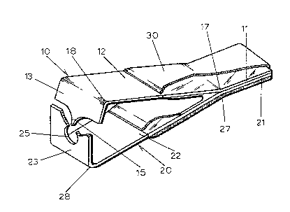
Figure l shows a right front perspective of the inven-
tion.
Figure 2 shows a right ront perspective view of the
invention in which the plastic that coats one end of the
invention has been broken away to show how the two strips
which ar~ coated by the plastic are joined and part of the
tab with an opening is broken away to show the point on the
other tab.
Detailed Description
Although the disclosure hereof is detailed and exact to
enable those skilled in the a~t to practice the invention,
the physical embodiments herein disclosed merely exemplify
; the invention which may be embodied in other specific struc-
ture. While the best known embodiment has been describedl
the details may be changed without departing from the inven-
tion which is defined by the claims appended hereto.
Referring now to Figures l and 2, the fi~hing jig eye
cleaner oi the present inv-ntion ha~ a top strip 10 and a

~L2~3Z0~2
bottom strip 20. The top strip 10 has a first, obtuse bend
17 which distinguishes an end portion 11 from an angled
portion 12 and a second, nearly right-angle bend 18, in the
opposite direction to bend 17, which creates a top tab 13 on
the angled portion 12. The bottom strip 20 also has an
obtuse bend 27 and a nearly right-angle bend 28 which
separates the bottom strip 20 into an end portion 21, an
angled portion 22, and a bottom tab 23.
Top or inner tab 13 and bottom or outer tab 23 begin at
respective bends 18 and 28 which are different distances
from respective obtuse bends 17 and 27. Top tab 13 is
closer to bend 17 than bottom tab 23 is to bend 27, so that
top tab 13 passes behind and substantially parallel to
bottom tab 23 and is spaced from bottom tab 23 at slightly
less than the length of a standard jig eye. Different
spacing may be provided for various eye sizes.
A tapered point 15 is formed at the center of the free
edge 14 of the top tab 13 on the top strip 10. An opening
25 is formed at a location on a line parallel to the path of
the point 15, normally at the center of the bottom tab 23 on
the bottom strip 20. The strips 10 and 20 are joined at
their adjacent end portions 11~ and 21 using known means so
that the angled portions 12 and 22 form an acute angle
between them. A plastic coati~g 30 is preferaby applied to
the two strips 10 and 20 covering the joined end portions 11
and 21 and partially covering the angled portions 12 and 22.
To operate the invention, the eye of the fishing jig or
hook (not shown) is inserted into the opening 25 so that the
eye is subs~antially parallel to the angled portion 22 o~
the bottom strip 20. Applying pressure to the angled
portions 12 and 22 causes point 15 to pass behind, substan-
tially parallel to, and across the entire width of opening
25. When the jig eye has been inserted into opening 25, the
point 15 will pass through the eye thereby punching out
paint or plastic which may be blocking the eye. Because
,

~ ~IZ~9Z
point 15 is tapered, it is capable of clearing jig eyes of
various sizes as long as they are large enough for the tip
of point 15 to pass through them yet small enough to be
properly positioned through the opening 25 in the path of
point 15. When released, angIed portions 12 and 22 and tabs
13 and 23 spring back to their original positions, so that
point 15 does not obstruct the opening 25 and the eye oE the
fishing jig or hook may be removed.
lthough the invention has been described as being
composed of two strips, it could alternatively be made out
of one strip which has been bent to create the end portions
11 and 21, angled portions 12 and 22, and tabs 13 and 23
previously described. Also, if the invention is formed Erom
a single strip, the angled portions 12 and 22 may meet
directly so that there are no end portions 11 and 21. In
general, the invention contemplates any device which has two
tabs 13 and 23 previously described which can be brought
together so that the point 15 of the inner tab 13 passes
substantially parallel to, behind, and across the ~ntire
width of the opening 25 in the ou~er tab 23 at a distance
substantially equal to the length of a jig eye or -Eish hook
eye.
,
.

Dessin représentatif
Une figure unique qui représente un dessin illustrant l'invention.
États administratifs

2024-08-01 : Dans le cadre de la transition vers les Brevets de nouvelle génération (BNG), la base de données sur les brevets canadiens (BDBC) contient désormais un Historique d'événement plus détaillé, qui reproduit le Journal des événements de notre nouvelle solution interne.

Veuillez noter que les événements débutant par « Inactive : » se réfèrent à des événements qui ne sont plus utilisés dans notre nouvelle solution interne.

Pour une meilleure compréhension de l'état de la demande ou brevet qui figure sur cette page, la rubrique Mise en garde , et les descriptions de Brevet , Historique d'événement , Taxes périodiques et Historique des paiements devraient être consultées.

Historique d'événement

Description Date
Le délai pour l'annulation est expiré 2007-03-26
Lettre envoyée 2006-03-27
Inactive : CIB de MCD 2006-03-11
Inactive : Grandeur de l'entité changée 2002-04-04
Accordé par délivrance 1991-03-26

Historique d'abandonnement

Il n'y a pas d'historique d'abandonnement

Historique des taxes

Type de taxes Anniversaire Échéance Date payée
TM (catégorie 1, 7e anniv.) - petite 1998-03-26 1998-03-26
Annulation de la péremption réputée 2001-03-26 1998-03-26
TM (catégorie 1, 8e anniv.) - petite 1999-03-26 1999-03-04
TM (catégorie 1, 9e anniv.) - petite 2000-03-27 2000-03-03
Annulation de la péremption réputée 2001-03-26 2001-03-14
TM (catégorie 1, 10e anniv.) - petite 2001-03-26 2001-03-14
TM (catégorie 1, 11e anniv.) - générale 2002-03-26 2002-03-26
TM (catégorie 1, 12e anniv.) - générale 2003-03-26 2003-02-28
TM (catégorie 1, 13e anniv.) - générale 2004-03-26 2004-03-09
TM (catégorie 1, 14e anniv.) - générale 2005-03-29 2005-03-11
Titulaires au dossier

Les titulaires actuels et antérieures au dossier sont affichés en ordre alphabétique.

Titulaires actuels au dossier
MILES A. MERTENS
Titulaires antérieures au dossier
S.O.
Les propriétaires antérieurs qui ne figurent pas dans la liste des « Propriétaires au dossier » apparaîtront dans d'autres documents au dossier.
Documents

Pour visionner les fichiers sélectionnés, entrer le code reCAPTCHA :


Pour visualiser une image, cliquer sur un lien dans la colonne description du document. Pour télécharger l'image (les images), cliquer l'une ou plusieurs cases à cocher dans la première colonne et ensuite cliquer sur le bouton "Télécharger sélection en format PDF (archive Zip)" ou le bouton "Télécharger sélection (en un fichier PDF fusionné)".

Liste des documents de brevet publiés et non publiés sur la BDBC .

Si vous avez des difficultés à accéder au contenu, veuillez communiquer avec le Centre de services à la clientèle au 1-866-997-1936, ou envoyer un courriel au Centre de service à la clientèle de l'OPIC.


Description du
Document 
Date
(aaaa-mm-jj) 
Nombre de pages   Taille de l'image (Ko) 
Dessins 1993-10-19 1 24
Page couverture 1993-10-19 1 13
Abrégé 1993-10-19 1 13
Revendications 1993-10-19 2 52
Description 1993-10-19 4 164
Dessin représentatif 2000-07-18 1 15
Avis concernant la taxe de maintien 2006-05-23 1 172
Taxes 2003-02-28 1 40
Taxes 1999-03-04 1 43
Taxes 2002-03-26 1 42
Taxes 2000-03-03 1 22
Taxes 1997-03-17 1 57
Taxes 1996-02-12 1 39
Taxes 1995-02-01 1 50
Taxes 1994-03-07 1 26
Taxes 1993-03-15 1 39