Note : Les descriptions sont présentées dans la langue officielle dans laquelle elles ont été soumises.
X835~'1
MECHANICAL SEAL TESTER
Description
This invantion relates to a mechanism for testing
mechanical seal assemblies under various, simulated
operation conditions and especia~y to an apparatus for
testing seal assemblies under various shaft misalignment
conditions~
A typical centrifu~al pump includes a motor driven
shaft which penetrates the pump housing. The shaft is
sealed to the housing by a mechanical seal assembly and is
supported by either a hydrostatic or other suitable bearing
means. During pump operation, the unbalanced radial load
at the pump .~mpeller, an inherent characteristic of centri-
fugal pumps, causes the shaft to shift and/or bend. The
shaft may also be displaced in the vertical direction
(axial) during operation due to shaft end thrust (pressure
l~ading) and thermal expansion. The magnitude and rate of
shaft displacement and/ox bending are dependent upon system
operating conditions, such as operating temperature, pres-
sure, and pump ~ow rate. Maximum radial displacement oroffset of the shaft occurs close to the position of the
seal elements of the seal assembly and a~fects the per-
formance thereof.
It is we~ understood that mechanical seal assemblies
for use in nuclear and/or toxic fluid assemblies must meet
higher standards o~ durability and "forgiveness" than
mechanical seal assemblies used in less exotic appli-
cations. It is, therefore, desirable to test a seal
assembly for a nuclear reactor pump under simulated
30 conditions rather than in an actual application. In this
'.
-2- ~356~
manner, the manufacturer can read;ly determine whether the
seal assembly is durable for its intended use.
To this end, the primary object of the present in-
vention is the provision of a seal testing apparatus in
which a seal assembly may be subjected to simulated changes
in shaft position and orbits, to permit an analysis of
whether the seal is durable for its intended use. More-
over, such an apparatus will permit the seal manufacturer
and/or user with test equipment which could be used in its
own facility for pretesting seals before installation in a
nuclear reactor pump.
Amongst its many features, the testing apparatus of
this invention simulates field operating conditions and
comprises a unique and specially engineered shaft assembly
having a series of seal assemblies arranged thereon. The
specially engineered shaft of the present invention allows
the test operator to vary the operative rotary path of the
shaft assembly. q'hat :Ls, the shaft assembly may be con-
trolled to rotate or turn with little or no eccentricity
or, alternatively, can be made to eccentrically rotate in
an orbit to simulate the radial displacement or offset of a
pump shaft caused by an unbalanced radial load as discussed
above. In this manner, and in a test environment, the
operator can analyze the seal assembly reaction to such
simulated conditions.
The shaft assembly of the present invention is
rotatably supported in a stationary frame of a seal tester
apparatus. The uni~ue shaft assembly comprises and ex-
tended hollow shaft having a bearing or support assembly
30 provided at the free ends thereof and a control mechanism
for affecting the rotary path of the shaft. Each bearing
or support assembly includes an apertured support member
secured to the free end of the shaft and a stub shaft
assembly rotatably mounted to said frame. Each stub shaft
--3--
:~L2~3356~L
has a first shaft portion which is received in a support
bearing of the frame assembly and a second shaft portion
which is eccentrically arranged with respect to the first
shaft portion. The eccentric shaft portion of each stub
shaft assembly is accommodated in the aperture or bore
provided in the support member. The aperture or bore in
the support member is eccentric~lly arranged relative to
the longitudinal axis of the extended shaft. One or both
of the stub shaft assemblies may be connected to a motor
]O ~or operably driving the shaft assembly. An operator
influenced control mechanism is further provided for con-
trolling the magmtude of shaft displacement. Intermediate
the ends of the shaft assembly, an equal series of seal
assemblies with their rotating parts to be tested are
1~ mounted to the outside diameter of the main shaft.
In addition to controlling the operative effect or
rotary path of the shaft assembly, the control mechanism
operably couples the extended ho~ow shaft to the rotatably
driven stub shaft assembly. To effect these ends, the
control mechanism includes at least one annular piston
which is carried within an enclosed space on said shaft and
is constrained to move between an initial or minimum
position and an extended or maximum position. A first
spline connection is provided between the piston and the
25 extended shaft wh~e a second spline connection is estab-
lished between the piston and a control gear fixed to the
driven stub shaft. As the control piston is axia~y moved,
it entails relative angular displacement of the eccentric
bore in the support member relative to the eccentric por
30 tion of the as~ociated stub shaft. As the control piston
causes the above mentioned relative rotation, the oparative
or total eccentricity of the extended shaft with respect to
the stub shaft varies from zero to a maximum value equal to
~he vector sum of ~he eccentricity of the support member
35 and the stub shafts.
-4- ~2~35~
Having in mind the above objects and other attendant
advantages that would be evident from an understanding of
this disclosure, the invention comprises the devices, combi-
nation and arrangement of parts as illustrated in the
presently preferred form of the invention which is herein-
after set forth in detail to enable those sk~led in the
art to readily understand the function, operation, con-
struction and advantages of same when read in conjunction
with the accompanying drawings in which:
FIGURE 1 is a side elevational view of a mechanical
seal testing apparatus in which the shaft assembly of the
present invention is used;
FIGURE 2 is a longitudinal cross-sectional view taken
along line 2-2 o~ FIGURE l;
FIGURE 3 is a cross-sectional view of the apparatus
of FIGURE 1 taken along line 3-3 of FIGURE l;
FIGURE 4 is a view, paxtly in cross section, of the
shaft assembly of this invention;
FIGURE 5 is an enlarged view, partly in
20 cross-section, of a portion of the shaft assembly of FIGURE
4; and
FIGURE 6 is a cross-sectional view taken alony line
6-6 of FIGURE 5.
Referring now to the drawings, wherein line reference
numerals indicate like parts throughout the several views,
the present invention is schematically illustrated in combi-
nation with a mechanical seal testing apparatus 10. It
will be appreciated, however, that the apparatus of the
present invention has a wide suitable application in impart-
3~ ing orbit~l motion to a rotary shaft and this disclosure is
, .
~5~ ~2~356~
not intended to overly limit the present invention.
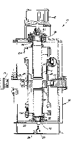
The testing apparatus 10 includes a support frame 12,a test cylinder 14 within the frame 12 and through which
the shaft assembly 16 of this invention passes, a motor 18
for rotating the shaft assembly and a swivel 20. In the
illustrated embodiment, the swivel 20 is connected to one
end of the shaft assembly 16 and to a source 22 of pres-
surized hydraulic fluid. An operator actuated control valve
24 is arranged between the source of fluid 22 and the
swivel 20. The test cylinder 14 is supported by ball bush-
Ings 26 shown in FIGURE 2, supported on spaced horizontal
trunnions 28. A mechanism 30 allows the test cylinder 14
to be tilted to test the schematically i~ustrated mecha-
nical seal assemblies 32 and 34, disposed within the
cylinder 14, under varying conditions. While the support-
ing trunnions, ball bushings, and tilting mechanism permit
various simulated condi~ons to be imparted to the tested
seals, they are not part of the invention to be described
herein and are i~ustrated and referred to for describing
the environment in which the present invention finds
u ~ ity.
The rotary shaft assembly 16 of this invention is
particularly i~ustrated in P`IGURES 4, 5 an 6 of the
drawings. The shaft assembly 16 includes an extended shaft
25 38 having a pair of shaft support assemblies 47 and 49
disposed at opposite ends thereof for mounting the shaft
c~ssembly to the frame assembly of the apparatus. The
extended shaft 38 has a longitudinal axis 39 and is
provided with an outside or exterior cylindrical surface 40
30 and an internal or axial bore 42 ex*ending the length
thereof. As best illustrated in FIGURES 4 and 5, the
internal bore 42 opens to an enlarged cylindrical and
axially arranged cavity or chamber 44 provided at one end
of the shaft 38. In the i~ustrated embodiment, at least a
35 portion of ~he cavity 44 is provided with internal gear
. .
--6--
~2~33561
teeth 46.
As was mentioned above, a primary object of this
invention is the provision of a tester assembly which may
subject mechanical seals to simulated changes in shaft
positions and/or orbits. To this end, the shaft support
a~ emblies 47 and 49 combine with a new and uni~ue control
mechanism 92 in order that the orbit31 or rotary path of
the shaft 38 may be varied at the will of the operator to
subject the seal assemblies 32 and 34 (FIGURE 2) mounted
about the shaft 38 to simulated field conditions. As will
be described in detail hereinafter, each of the shaft
support assemblies includes a variable eccentric mechanism
which, in combination with the control mechanism 92, im-
parts the desired degree or magnitude of orbital motion to
the shaft 38. The control mechanism 92 is effective to
adjust the operative effect of the variable eccentric
mechanisms whereby achieving the functional equivalent of
having to continua~y replace a multitude of fixed throw
eccentrics normally used for imparting various orbital
motions to a shaft. For purposes of this description,
suffice it to say, the operative radius or eccentricity of
the variable eccentric mechanism is that which, in a device
utilizing fixed throw eccentrics, would normally be effec-
tive to impart the observed magnitude of eccentric rotary
or orbital movement to the shaft 38. Furthermore, while
the shaft 38 is turning, the control mechanism 92 is
capable of effecting a smooth and rapid change in the
operative effect said variable eccentric mechanism wi~
have regarding the orbital path traversed by the rotating
3~ shaft 38~ Thus, unnecessary interruptions in testing the
seal assemblies under various shaft misalignment conditions
are eliminated~
Each of the shaft support assemblies 47 and 49
includes a bearing carrier, a stub shaft, and means for
rotatably supporting each shaft supporting assembly
.
.
~Z8356~
relative to the frame. Specifically, the upper shaft sup-
port assembly 47 includes a generally cylindrical carrier
48 which is affixed to one end of the shaft 38. The other
and lower bearing support 49 is also provided with a gene-
rally cylindrical carrier 50 which is affixed to the oppo-
site end of the shaft 38. To reduce unbalanced forces, the
outside diameters of the carriers 48 and 50 are machined to
be concentric with the cylindrical outer surface of the
shaft 38. Each of the carriers 48 and 50, is provided with
10 a bore 52 and 54, respectively, which i5 eccentrically
arranged relative to the longitudinal axis 39 of the shaft
38. In the preferred embodiment, the eccentricities of the
bores 52 and 54 relative to the longitudinal axis of the
shaft are substantially similar. It will be appreciated,
15 however, that the eccentricitie.s of the bores relative to
the longitudinal axis of the shaft may be different if a
different result is desired.
As mentioned, each shaft support assembly further
includes a stub shaft. In the illustrated embodiment, the
20 first or upper stub shaft 56 is driven by the motor 18
~IGURE 1). The stub shaft 56 is rotatably supported in
spaced bearings 58, 60 ~arried in the eccentric bore 52 of
the bearing carrier 48. The stub shaft 56 is divided into
first, second and third shaft sections 62, 64, and 74,
25 respectively. The first shat section or portion 62 of the
stub shaft 56 is accommodated for rotation within the
carier 48 and is eccen~rically arranged relative to the
second shaft portion 64. The second portion 64 is
rvtatably supported in a shaft assembly thrust bearing 66
30 housed in a vertical height adjustment mechanism 68
~IGURES 1 and 2) which is supported by the support frame
12 of the apparatus. The third section 74 is a depending
coaxial ex*ension of shaft portion 64 and extends into the
bore 42 of the shaft 38 for reasons hereinafter described.
A second and lower stub shaft 70 is provided as part
~,
~283561
of the other shaft support assembly 49. Like stub shaft
56, this second stub shaft 70 is provid~d with first,
second, and thlrd shaft sections or portions 86, 84, and
76, respectively. The ~irst and second stub shafts 56 and
may be operably connected such that shaft eccentricity
will be adjusted equally end to end. To connect the stub
shafts, the extended poxtions 76 and 74 of the stub shafts
56 and 70 are pinned or otherwise connected as at 72. The
lower stub shaft 70 is rotatably mounted in spaced bearings
78 and 80 carried in the eccentric aperture 54 of the lower
bearing carrier 50 and is rotatably supported by the
bearing portion 86 which is received in a radial bearing 82
fixed to the support framework 12 (FIGURE 2) of the
apparatus. The shaft portion 84 of the lower stub shaft
70, arranged between bearings 78 and 80, is formed
eccentric to the other portions 76 and 86 of the stub shaft
70. Moreover, the lower stub shaft is provided with a bore
88 which axially extends therethrough. The bore 88
permits the cavity 4~ in the main shaft 38 to be in fluidic
communication with the swivel 20 (FIGURE 2) which, in the
preferred embodiment, is fixed to the lower end of the
shaft 38. In the preferred embodiment, the eccentricity of
the stub shaft portions 62 and 84 are substantia~y simi-
lar~ It w~l be appreciated, however, that the eccentri-
city of these elements can be different if a differenteffect is desired. Moreover, the magnitude of the
eccentricity of the stub shaft portions ~2 and 64 is
substantially equal to that of the bores 52 and 54 relative
b~ the longitudinal axis 39 of the extended shaft 38.
As mentioned above, the orbital path of travel of the
shaft assembly 16 is contro~ed by a mechanism 92, now to
be described. The control mechanism serves a dual
purpose: first, it conkrols the orbital path of the
rotating shaft assembly; and, second, it operably couples
thP extended shaft 38 to the driven stub shaft. In the
presently preferred embodiment, the control mechamsm 92
, ' :
., .
9 ~Z~33~;6~
includes an annular fluidically responsive piston 94 which
axially moves in the channel 44 between an initial position
and an extended position. A first spline connection is
established between an outer grooved or toothed surface 96
5 provided on the piston 94 and a complimentary toothed sur-
face 46 provided in the chamber 44. As hest i~ustrated in
FIGURE 6, a second spline connection is established between
an inner grooved or toothed surface 98 of the piston and
the outer toothed surface 100 of control gear 102. The
10 control gear 102 is affixed or keyed to the extended sec-
tion 74 of the stub shaft 56. In order for the shaft
assembly to function in the manner hereinafter descrlbed,
at least one of the above mentioned spline connections is
required to be helicoidal. The interior of the piston 94
is provided with helical gear teeth 98 which engage and
mesh with the exterior helical gear teeth 100 of the
control gear 102.
Because the shaft support assemblies 47 and 49 are
interconnected, a common control mechanism, such as 9~,
20 impar~s equal degrees of eccentircity to both ends of the
shaft assembly 16. The provision of two separate control
mechanisms for allowing separate control of each shaft
support assembly, however, is within the intended scope of
this invention. If two control mechanisms were provided,
25 the operative eccentricity of each end of the 6haft 38
could be regulated independently. Moreover, using direct
mechanical rather than hydraulic force, for controlling the
disposition of the control mechanism is within the spirit
of the present inven~on.
As best illustrated in FIGURE 2, two seal cartridges
with ~he same set of mechanical seals, such as previously
identified seals 32 and 34, are tested at one time. The
seals are preferably placed back-to-back in the seal tester
~o avoid producing high axial thrusts. Each seal assembly
35 is assembled about the outside diameter of the shaft
. . .
.
--10--
~2~3356~
assembly 15 and is retained by a clamp 104 or 106 bolted to
the end of the kest cylinder 14.
An exemplary operative sequence of the present in-
vention wi~ now be described. The stub shaft connected to
5 motor 18, through the control gear 102, rotatably drives
the extended shaft 38 about its longitudinal axis. When
the control piston 94 is disposed in its imtial position,
the shaft assembly 16 wi~ be ro~ated about an axis which
is coincident with the longitudinal axis 39 of shaft 38
such that a minimum circumferential rotary path of travel
for the extended shaft 38 is achieved or effected. On the
other hand, when the control piston 94 is disposed in its
extended position, the shaft assembly 16 will move in an
eccentric or orbital path having a maximum circumferential
15 rotary path of travel for the extended shaft 38.
Absent axial movment of piston 94, the eccentric
relationship between the eccentric elements comprising the
shaft support assemblies 47 and 49 remains the same for all
rotational speeds of the shaft assembly 16. Axial move-
20 ment, however, of the piston 94 ef~ects a modification of
the eccentric relationship between such elements and there-
by modifies the operative effect the shaft support assem-
blies have on the rotational path of shaft 38. Axial move-
ment of the piston is effected by the operator adjusting
25 the pressure in cavity 44. As the piston 94 is forcibly
moved under hydraulic pressure, introduced to the chamber
44 through the swivel 20 and interconnecting passageway 88,
the piston 94 cannot rotate with respect to the shaft 38
because of the spline connection ~herebetween. Since the
30 piston 94 cannot rotate with respect to the shaft, the
helical control gear 102 must rotate if the piston 94 is to
move. Ro~ation of the helical control gear wi~ likewise
af~ect rotation of ~he s~ub sha~t with its eccentric crank
portion and, thus, cause a modification or change in the
35 eccentric reltionship between eccentric crank portions 6~
1283SGl
and 84 of stub shafts 56 and 70, respectively, and the
eccentric bores 52 and 54 of the bearing carriers 48 and 50
mounted on the extended sha~t 38. Such a change in the
mounting s~ructure for the shaft has an effect on the orbi-
tal path of the shaft assembly. When hydraulic forces areremoved from the piston, for whatever reason, the fric-
tional torque characteristics of the seal assemblies cause
the control mechanism 92 to return to its initial position
whereat the shaf~ assembly turns concentrically about the
JDngitudinal axis 39 of the shaft 38. That is, frictional
torque applied to ~he outside diametRr 40 of the shaft 38
is converted to an axial force on the piston by the in-
~lined heLical teeth on the control gear 102. When hy-
draulic forces are removed from the piston, this axial
force is sufficient to ~orcibly return the piston to its
initial position.
As a skilled artisan will appreciate, the total
eccentricity of the shaft 38 with respect to the stub shaft
56, 70 is the vector sum of the stub shafts' eccentricity
and the carrier's eccentricity. As the eccentric rela-
tionship between the stub shafts' eccentric portions 62, 84
and the eccentric bores 52, 54 changes, the vector sum
changes, causing the total eccentricity of the shaft 38
relative to the stub shaft 56, 72 to vary from zero to a
25 maximum value over the total axial travel of the piston 94.
Thus, there has been provided a MECHANICA~ SEAL
TESTER which fully satisfies the objects, aims and
advantages set forth above. While the invention has been
described in connection with a specific embodiment thereof,
30 it is evident that many ~lternatives, modifications and
variations w;ll be apparent to those skilled in ~he art in
light of the foregoing description. Accordingly, it is
intended to embrace all such alternatives, modifications,
and variations as fall within the spirit and broad scope of
35 the appended claims.