Sélection de la langue

Search

Sommaire du brevet 1284135 

Énoncé de désistement de responsabilité concernant l'information provenant de tiers

Une partie des informations de ce site Web a été fournie par des sources externes. Le gouvernement du Canada n'assume aucune responsabilité concernant la précision, l'actualité ou la fiabilité des informations fournies par les sources externes. Les utilisateurs qui désirent employer cette information devraient consulter directement la source des informations. Le contenu fourni par les sources externes n'est pas assujetti aux exigences sur les langues officielles, la protection des renseignements personnels et l'accessibilité.

Disponibilité de l'Abrégé et des Revendications

L'apparition de différences dans le texte et l'image des Revendications et de l'Abrégé dépend du moment auquel le document est publié. Les textes des Revendications et de l'Abrégé sont affichés :

  • lorsque la demande peut être examinée par le public;
  • lorsque le brevet est émis (délivrance).
(12) Brevet: (11) CA 1284135
(21) Numéro de la demande: 1284135
(54) Titre français: ENCHAINEMENT DE SACS D'EMBALLAGE
(54) Titre anglais: CONTINUOUS BAG STRIP
Statut: Périmé et au-delà du délai pour l’annulation
Données bibliographiques
(51) Classification internationale des brevets (CIB):
  • B65D 30/10 (2006.01)
  • B65D 33/06 (2006.01)
(72) Inventeurs :
  • LLORENS, RAFAEL GONZALEZ (Espagne)
  • SOLE, JUAN VIDAL (Espagne)
(73) Titulaires :
  • RAFAEL GONZALEZ LLORENS
  • JUAN VIDAL SOLE
(71) Demandeurs :
(74) Agent: MCCARTHY TETRAULT LLP
(74) Co-agent:
(45) Délivré: 1991-05-14
(22) Date de dépôt: 1985-08-27
Licence disponible: S.O.
Cédé au domaine public: S.O.
(25) Langue des documents déposés: Anglais

Traité de coopération en matière de brevets (PCT): Non

(30) Données de priorité de la demande:
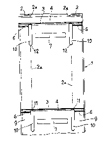
Numéro de la demande Pays / territoire Date
281.395 (Espagne) 1984-08-29

Abrégés

Abrégé anglais


ABSTRACT
A continuous bag strip, particularly applicable for use
in bag dispensing machines, of the type consisting of a flat,
continuous, conventional tubular strip of a flexible plastic
material, fitted in each of the longitudinal edges with an
inward longitudinal fold and which has several groups of
equidistantly separated transverse lines at a distance equal to
the length of the bag, and consisting of a welding line which
makes up the bottom of each bag and a perforation line near the
welding line, so as to be able to separate each bag from the
others is disclosed. On each inward fold line for each
longitudinal fold, an oblong, longitudinal opening is made by
die cutting. This opening is parallel to the longitudinal edge
of the strip, so the longitudinal edges of each oblong opening
are located in such a way that there is one on each side of the
inward fold line. One of the transverse edges of the oblong
opening is on the perforation line or between this line and the
corresponding, adjacent welding line which makes up the bottom
of the bag, while the other transverse edge is generally
semi-circular.

Revendications

Note : Les revendications sont présentées dans la langue officielle dans laquelle elles ont été soumises.


WE CLAIM:
1. A continuous bag strip separable into a plurality of bags
comprising a flat, continuous tubular strip of flexible plastic
material having opposite sides and longitudinal edges each of
which edges has an inward longitudinal fold made along a fold
line, said strip having a plurality of longitudinally spaced
transverse weld lines extending from one longitudinal edge of
said strip to the other and a plurality of transverse perforation
lines each located close to a respective weld line and extending
from one longitudinal edge of said strip to the other such that
said strip may be separated at said perforation lines into bags
each having a bottom formed by one of said weld lines, each side
of said strip having a plurality of longitudinally elongated die-
cut openings at the location of each of said fold lines, each
opening having two longitudinal edges and two transverse edges;
one transverse edge of each opening lying in a region extending
from a perforation line to adjacent the corresponding adjacent
weld line and the other transverse edge of each opening being
substantially semi-circular in shape, said strip further
including a plurality of second transverse weld lines each of
which extends from one longitudinal edge of one of said openings
to the corresponding side of the strip joining both sides of the
same with said fold.
2. A continuous bag strip as defined in claim 1 including in at
least one side of said strip, 8 plurality of holes adapted to
activate a device which detects the passage of each bag in a bag
dispensing machine, each of said holes being located between a
respective pair of said openings.

3. A continuous bag strip as defined in claim 1 including in at
least one side of said strip, a plurality of optically detectable
indicia adapted for activating a device which detects the passage
of each bag in a bag dispensing machine, each indicia being
located between a respective pair of said openings.
4. A continuous bag strip separable into a plurality of bags
comprising a flat, continuous tubular strip of flexible plastic
material having opposite sides and longitudinal edges each of
which edges has an inward longitudinal fold made along a fold
line, said strip having a plurality of longitudinally spaced
apart transverse weld lines extending from one longitudinal edge
of said strip to the other and a plurality of transverse
perforation lines each located close to a respective weld line
and extending from one longitudinal edge of said strip to the
other such that said strip may be separated at said perforation
lines into bags each having a bottom formed by one of said weld
lines, each side of said strip having a plurality of
longitudinally elongated die-cut openings at the location of each
of said fold lines, each opening having two longitudinal edges
and two transverse edges; one transverse edge of each opening
lying in a region extending from a perforation line adjacent
the corresponding adjacent weld line and the other transverse
edge of each opening being substantially semi-circular in shape.
5. A continuous bag strip as defined in claim 4 including in at
least one side of said strip, a plurality of holes adapted to
activate a device which detects the passage of each bag in a bag

dispensing machine, each of said holes being located between a
respective pair of said openings.
6. A continuous bag strip as defined in claim 4 including in at
least one side of said strip, a plurality of optically detectable
indicia adapted for activating a device which detects the passage
of each bag in a bag dispensing machine, each indicia being
located between a respective pair of said openings.
7. A continuous bag strip as defined in claims 1 or 4 wherein
each bag has a pair of said openings extending in substantially
parallel relationship from the perforation line associated with
each bag so that each bag has a pair of lobes respectively in the
sides thereof, each lobe continuously extending from the
perforation line to said semi-circular
transverse edges of the openings.
8. A continuous bag strip as defined in claim 4 wherein each
bag has at least one optically datectable indicia disposed on at
least one of its lobes, said indicia being adapted to detect the
passage of the bag in a bag dispensing machine.
9. A continuous bag strip as defined in claim 4 wherein each
bag has at least one hole disposed in at least one of its lobes,
said hole being adapted to detect the passage of the bag in a bag
dispensing machine.
10. A continuous bag strip as defined in claim 4 including a
plurality of second transverse weld lines each of which extends

from one longitudlnal edge o:E said strip to an ad~ acent
longitudinal edge of one of said openings.

Description

Note : Les descriptions sont présentées dans la langue officielle dans laquelle elles ont été soumises.


-- 1 --
The present invention refers to a continuous bag ~trip,
of the -type of those used in bag dispensing machines common-
ly called the "vest" type, and which present an ample recess
between the two ~ide handles. These bags are initially join-
ed together, forming the strip in which some per~oration lines
which affect the top part of the handles are made. The pur-
pose o~ this per~oration is to be able to separate each bag
from the following bag. ~his is carried out by applying
action w-th some pulling mean~ to be found on the actual d;s-
pensing machine~ although it usually ~appens, due to the
mentioned traction, that the bags get creased and on occ~sion~
even break at the narrow wea~ part~ where the handles are
joined.
This problem waR to be solved by making a continuou~ bag
strip in ~rhich the big opening corresponding to the recess
between the handles was suppressed, at the same time as the
per~oration lines were placed to OGCUpy the complete width of
the strip, with two longitudinal cuts having been envisagedO
~hese cuts affect each side of the continuous strip for each
bag, with the aim of determining the recess and the formation
of ~he handles once each bag is separated from the following
one.
However9 in this realization, an important drawback ap-
pears: with the cutting operation, to give ri~e to the cuts
which will determine the opening corresponding to the reces~
and produce the separation between the bags, the formation of
some small, stretched pieces left o~er from the plastic mat-
erial which has been cut takes place. These left overs gen
erally stay inside each bag, and this produces a nuisance and
unpleasant effect for the person using the bag.
It is an object of the present invention to obviate or
mitigate the above-mentioned disadvantages.
. ~

- 2 - ~ 3~
Accordingly, the present invention provides a continuous bag
strip separable into a plurality of bags comprising a ~lat,
continuous tubular strip of flexible plastic material having
opposite sides and longitudinal ed~es each of which edges has an
inward longitudinal fold made along a fold line, said strip
h~ving a plurality of longitudinally spaced transverse weld lines
extending from one longitudinal edge of said strip to the other
and a plurality of transverse perforation lines sach located
close to a respective weld line and extending from one
longitudinal edge of said strip to the other such that said strip
may be separated at said perforation lines into bags each having
a bottom formed by one of said weld lines, each side of said
strip having a plurality of longitudinally elongated die-cut
openings at ths location of each o sald fold lines, each opening
having two longitudinal edges and two transverse edges; one
transverse edge of each opening ~lying in a region extending from
a perforation line to adjacent the corresponding ad~acent weld
line and the other transverse odge of each opening being semi-
circular in shape, said strip further including a plurality of
second transverse weld lines each of which extends from one
longitudinal edge of one of said openings ~o the corresponding side
of the strip joining both sides of the same with said fold.
With the pn~nt L~R~ticn, a 5~n~s in pl~ic i8 adh1ow~c as a
la~ piece i~ left c~er, which can be r o~ed in the C~in~ as the die
cutting o~ the ma~erial gi~es rise bo an ~ g ins~ of a ~imple cut.
~he bag is also more aestbetically ple~l~ ~ the pri~r art kag3.
~ o ~acilitate ~h~ erplanation~ ~o~e diagram~ are e~closed
with the preseD~ de~criptive report. In these diagrams, a
p~eferred em~odi~ent Or ~he ~trip in qUestion ~a~ bee~ re-
presented, ~nd is gi~en only as a non-limiting example Of
the scope o~ this in~ention.
Figure 1 illustrates a top view of a preferred ~anner
of realization of the strip.
Fi~ure 2 represents a perspective view of an unrolled bag
of the strip and
Figure 3 also shows a perspective view of a bag which ha~
been sep2rated from t~e strip~
" ,. '

3~i
-- 3 --
In the preferred embodiment of the invention represented
in the enclosed diagrams, i~ can be seen that it includes a
flat, continuous, conventional tubular strip, 1, of a flexible
plastic material, which on its l.ongitudinal edges has inward
folds, 2. strip 1 has some transver~sal weldiny lines 3 which
make up the respective bottoms of the bags, and some perforakion
lines 4, which are also transversal and near the pre~ious ones,
for separating one bag from the following one.
On each inward fold line 2a of each longitudinal fold,
an oblong, longitudinal opening is made by die cutting 10.
This opening 10 is parallel to the longitudin~.l edge of the
strip 17 SO the longitudinal edges of each oblon~ opening 10
are in such a way that there is one on each side of the ment-
ioned inward fold line 2a, an.d one of the transversal edges
11 on the perfora~io~ line 4 or between this line znd the
corresponding adjacent ~relding line 3 which makes up the
bottom of the b~g9 while the other transversal edge 12 is
an appre~iab~y- semicircumferen~ial shape.
For each bag~ two trans~ersal ~/elding lines 6 have been
en~isaged, and they are close to the perforation line 4
and go from each opening 10 to the corresponding side of the
strip, joining both sides of the sa~e with the respective
fold 2.
~ he dispensing machines which supply. individual bag~ from
a continuous strip 1 are usually fitted with an organ ~rhich
detects the passage of each bag to be suppliedO ~he com-
ponents of this organ are situated on both sides of the
continuous strip 1, carrying out the detection ~hrough the
recess ~hich the vest type bags haveO As ~he bag which is
the object of this invention precisely lacks the recess, so
as not to weaken the body of the bag and to resist wi~hout
getting creased or deformed, the traction stresses produced
by the mechanism of the machine that will separate it ;from
the rest of strip 1~ each side of the bag ha~ openings or
optically detectable signs 7 of the right size to allow the
acting of the mentioned bag passage detecting organ.

-- 4 --
As an effect of the traction applied by the traction
means, such a~ rollers or others included in the dispensing
machine, each bag is separated from the next one when strip
1 is torn by the perforation lines 4,owing to ~rhich, from
these lines and the opening lines 10, two lobes 8 are de
termined in each bag and they fall on the outsides of the
bag itself. ~he welding lines 6 join the sides of strip 1
with the fold 2, so that the handles 9 are formed, as sho~m
in figures 2 and 3.
Everything that does not alter, change or modify the
essence of the continuous bag strip described may remain
~ubject to variation in details. I
' . . - -

Dessin représentatif
Une figure unique qui représente un dessin illustrant l'invention.
États administratifs

2024-08-01 : Dans le cadre de la transition vers les Brevets de nouvelle génération (BNG), la base de données sur les brevets canadiens (BDBC) contient désormais un Historique d'événement plus détaillé, qui reproduit le Journal des événements de notre nouvelle solution interne.

Veuillez noter que les événements débutant par « Inactive : » se réfèrent à des événements qui ne sont plus utilisés dans notre nouvelle solution interne.

Pour une meilleure compréhension de l'état de la demande ou brevet qui figure sur cette page, la rubrique Mise en garde , et les descriptions de Brevet , Historique d'événement , Taxes périodiques et Historique des paiements devraient être consultées.

Historique d'événement

Description Date
Inactive : CIB de MCD 2006-03-11
Inactive : Demande ad hoc documentée 1994-05-14
Le délai pour l'annulation est expiré 1993-11-16
Lettre envoyée 1993-05-14
Accordé par délivrance 1991-05-14

Historique d'abandonnement

Il n'y a pas d'historique d'abandonnement

Titulaires au dossier

Les titulaires actuels et antérieures au dossier sont affichés en ordre alphabétique.

Titulaires actuels au dossier
RAFAEL GONZALEZ LLORENS
JUAN VIDAL SOLE
Titulaires antérieures au dossier
S.O.
Les propriétaires antérieurs qui ne figurent pas dans la liste des « Propriétaires au dossier » apparaîtront dans d'autres documents au dossier.
Documents

Pour visionner les fichiers sélectionnés, entrer le code reCAPTCHA :


Pour visualiser une image, cliquer sur un lien dans la colonne description du document. Pour télécharger l'image (les images), cliquer l'une ou plusieurs cases à cocher dans la première colonne et ensuite cliquer sur le bouton "Télécharger sélection en format PDF (archive Zip)" ou le bouton "Télécharger sélection (en un fichier PDF fusionné)".

Liste des documents de brevet publiés et non publiés sur la BDBC .

Si vous avez des difficultés à accéder au contenu, veuillez communiquer avec le Centre de services à la clientèle au 1-866-997-1936, ou envoyer un courriel au Centre de service à la clientèle de l'OPIC.


Description du
Document 
Date
(aaaa-mm-jj) 
Nombre de pages   Taille de l'image (Ko) 
Revendications 1993-10-19 4 127
Abrégé 1993-10-19 1 27
Dessins 1993-10-19 2 41
Description 1993-10-19 4 170
Dessin représentatif 2001-11-08 1 8