Sélection de la langue

Search

Sommaire du brevet 1284519 

Énoncé de désistement de responsabilité concernant l'information provenant de tiers

Une partie des informations de ce site Web a été fournie par des sources externes. Le gouvernement du Canada n'assume aucune responsabilité concernant la précision, l'actualité ou la fiabilité des informations fournies par les sources externes. Les utilisateurs qui désirent employer cette information devraient consulter directement la source des informations. Le contenu fourni par les sources externes n'est pas assujetti aux exigences sur les langues officielles, la protection des renseignements personnels et l'accessibilité.

Disponibilité de l'Abrégé et des Revendications

L'apparition de différences dans le texte et l'image des Revendications et de l'Abrégé dépend du moment auquel le document est publié. Les textes des Revendications et de l'Abrégé sont affichés :

  • lorsque la demande peut être examinée par le public;
  • lorsque le brevet est émis (délivrance).
(12) Brevet: (11) CA 1284519
(21) Numéro de la demande: 1284519
(54) Titre français: ENTRAINEMENT ELECTRONIQUE REFROIDI PAR AIR
(54) Titre anglais: AIR COOLED ELECTROMECHANICAL DRIVE APPARATUS
Statut: Durée expirée - après l'octroi
Données bibliographiques
(51) Classification internationale des brevets (CIB):
  • H02K 9/00 (2006.01)
  • B66C 13/22 (2006.01)
  • B66D 1/12 (2006.01)
  • H02K 7/10 (2006.01)
  • H02K 7/116 (2006.01)
  • H02K 11/33 (2016.01)
  • H02M 5/293 (2006.01)
  • H02P 27/16 (2006.01)
(72) Inventeurs :
  • JUSSILA, OLAVI (Finlande)
(73) Titulaires :
  • KONE OY
(71) Demandeurs :
  • KONE OY (Finlande)
(74) Agent: G. RONALD BELL & ASSOCIATES
(74) Co-agent:
(45) Délivré: 1991-05-28
(22) Date de dépôt: 1987-12-18
Licence disponible: S.O.
Cédé au domaine public: S.O.
(25) Langue des documents déposés: Anglais

Traité de coopération en matière de brevets (PCT): Non

(30) Données de priorité de la demande:
Numéro de la demande Pays / territoire Date
865294 (Finlande) 1986-12-23

Abrégés

Abrégé anglais


ABSTRACT OF THE DISCLOSURE
An electromechanical drive has an a.c. motor
provided with a brake, a frequency converter provided with
a control unit and supplying the motor, and a transmission
gearing connected to the output of the motor. To achieve
efficient cooling, the drive is provided with a cooling
tunnel housing the motor and the brake; the control unit
and the power stage semiconductor switches of the
frequency converter are located on the outer walls of this
tunnel; and the transmission gear is located in or
adjacent the tunnel.

Revendications

Note : Les revendications sont présentées dans la langue officielle dans laquelle elles ont été soumises.


THE EMBODIMENTS OF THE INVENTION IN WHICH AN
EXCLUSIVE PROPERTY OR PRIVILEGE IS CLAIMED ARE DEFINED AS
FOLLOWS:
1. An electromechanical drive comprising:
an a.c. motor;
a brake associated with said a.c. motor;
a frequency converter provided for supplying
said motor;
said frequency converter comprising power stage
semiconductor switches;
means for controlling said frequency converter;
a transmission gearing connected to the output
of said motor;
a cooling tunnel housing said motor and said
brake;
said control means and said power stage
semiconductor switches of said frequency converter being
located on outer walls of said cooling tunnel; and
said transmission gearing being located in or
adjacent said cooling tunnel.
2. An electromechanical drive according to
claim 1, further comprising fan means for producing an air
flow through said cooling tunnel to cool said transmission
gearing, said motor, said brake, said power semiconductor
switches and said control means.
3. An electromechanical drive according to
claim 1, further comprising cooling ribs provided
internally on said cooling tunnel.
4. An electromechanical drive according to
Claim 1, 2, or 3 wherein said transmission gearing
comprises a speed reduction gearing for providing a
rotational speed below that of said motor.
5. An electromechanical drive according to
Claim 1, 2, or 3 further comprising tachometer means

associated with said cooling tunnel for providing speed
feedback.

Description

Note : Les descriptions sont présentées dans la langue officielle dans laquelle elles ont été soumises.

The present invention relates to an
electromechanical drive means comprising an a.c. motor
provided with a brake, a frequency converter provided with a
control unit and supplying the motor, and a gearing for
pro~ucing a rotational speed differing from that of the motor.
The hoisting motors currently used in hoisting
means, such as cranes, are bulky and expensive. The
electronic equipment controlling the motor occupies a large
space and is placed in separate instrument cabinets. The
separate placement of the electronics involves the use of
long cables. Moreover, high-power motors require a sizeable
brake, which also takes up a large space.
It is accordingly an object of the present invention
to eliminate the drawbacks mentioned.
According to the present invention, an
electromechanical drive comprises an a.c. motor; a brake
associated with the a.c. motor, a frequency converter provided
for supplying the motor, the frequency converter comprising
power stage semiconductor switches, means for controlling the
frequency converter, a transmission gearing connected to the
output of the motor, a cooling tunnel housing the motor and
the brake, the control means and the power stage semiconductor
switches of the frequency converter being located on outer
walls of the cooling tunnel, and the transmission gearing
being located in or adjacent the cooling tunnel.
In the drive according to the present invention,
all heat generating components may be located inside or around
the same cooling tunnel. The transmission gearing steps the
output speed of the motor to a required level, so that the
drive may be substituted for a motor controlled by the mains
frequency. Since the frequency converter makes it possible
to use a low motor torque, the brake required for the motor
may also be small. The drive according to the present
invention may be smaller in volume than a normal frequency
motor. The same motor can be used within a wide power range,
which is of advantage
~3 ~.

in view of maintenance and spare parts. Furthermore, the
cable and wiring connections are short.
A preferred embodiment of the electromechanical
drive, according to the present invention comprises fan
means for producing an air flow through the cooling tunnel
to cool the transmission gearing, the motor, the brake,
the power semiconductor switches and the control means.
T h e p r e f e r r e d e m b o d i m e n t of th e
electromechanical drive of the invention also comprises
cooling ribs provided internally on the cooling tunnel,
and the transmission gearing comprises a speed reduction
gearing for providing a rotational speed below that of the
motor. Tachometer means are associated with the cooling
tunnel.
An embodiment of the present invention is
described in the following in greater detail by way of
example and with reference to the accompanying drawings,
in which:
Figure 1 shows a hoisting motor unit embodying
the present invention, and
Figure 2 shows the hoisting motor unit of Figure
1 taken in section along the line A-A of Figure 1.
The hoisting motor unit shown in Figure 1, which
is intended for use in a crane or the equivalent,
comprises a squirrel-cage motor 1 provided with a disc
brake 2. The squirrel-cage motor 1 is coupled to a
reduction gearing 3 to produce a lower rotational speed.
The motor 1 is located in a cooling tunnel 5, the brake 2
being mounted on the motor 1. For improved air
circulation, indicated by arrows in Figure 1, the cooling
tunnel 5 is provided with a fan 4. As shown in Figure 1,
the reduction gearing 3 is located at the mouth of the
tunnel 5. The gearing is mounted on a flange 6 by which
the hoisting motor unit 1 is attached to a crane or the
equivalent.
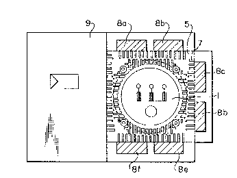
Figure 2 shows a section through the hoisting
motor unit taken along line A-A in Figure 1. The tunnel 5
is provided with internal cooling ribs 7 for improved

cooling efficiency. The cooling ribs may be made e.g. of
extruded sectional aluminium. The cooling ribs 7 provide
a large cooling surface. The frequency converter, which
consists of a power stage and a control unit, supplies the
motor with a frequency exceeding the mains frequency, e.g.
70-300 Hz or above. The power available from the motor
increases in proportion to the frequency. Thus, at a
frequency of 300 Hz the motor yields a power about six
times that obtained at a frequency of 50 Hz. Using the
reduction gearing 3 as shown in Figure 1, the speed of
rotation is reduced to within the range of 1000-1500
r.p.m. which is the standard speed range of a squirrel-
cage motor operated from a 50 Hz or 60 Hz mains supply.
Thus, the hoisting motor unit is interchangeable with a
mains-operated squirrel-cage motor. As shown in Figure 2,
the control unit 9 and the power transistors 8a-8f of the
power stage of the frequency converter are mounted on the
external walls of the cooling tunnel 5, the control unit 9
being located on one wall and the transistors 8a-8f of the
three-phase frequency converter on the other three walls.
In addition to the brake 2, a tachometer 10 may
be mounted on the motor to provide speed feedback. When
the reduction gear 3 is placed as shown in Figure 1 in the
vicinity of the mouth of the tunnel 5, all heat generating
components are located close to the cooling tunnel, the
result being a concentrated cooling system that
efficiently cools the transmission gearing 3, the motor 1
and the brake 2 as well as the power stage and control
unit 9 of the converter. A stepless speed control system,
rendered possible by the use of a frequency converter, is
thus located in the same unit with the motor 1.
It will be obvious to those skilled in the art
that the embodiments of the invention are not restricted
to the example discussed above, but that they may instead
be varied within the scope of the following claims.

Dessin représentatif
Une figure unique qui représente un dessin illustrant l'invention.
États administratifs

2024-08-01 : Dans le cadre de la transition vers les Brevets de nouvelle génération (BNG), la base de données sur les brevets canadiens (BDBC) contient désormais un Historique d'événement plus détaillé, qui reproduit le Journal des événements de notre nouvelle solution interne.

Veuillez noter que les événements débutant par « Inactive : » se réfèrent à des événements qui ne sont plus utilisés dans notre nouvelle solution interne.

Pour une meilleure compréhension de l'état de la demande ou brevet qui figure sur cette page, la rubrique Mise en garde , et les descriptions de Brevet , Historique d'événement , Taxes périodiques et Historique des paiements devraient être consultées.

Historique d'événement

Description Date
Inactive : CIB attribuée 2019-06-27
Inactive : CIB enlevée 2019-06-27
Inactive : CIB attribuée 2019-06-27
Inactive : CIB enlevée 2019-06-27
Inactive : CIB attribuée 2019-06-27
Inactive : CIB enlevée 2019-06-27
Inactive : CIB attribuée 2019-06-27
Inactive : CIB enlevée 2019-06-27
Inactive : CIB expirée 2016-01-01
Inactive : CIB enlevée 2015-12-31
Inactive : Périmé (brevet sous l'ancienne loi) date de péremption possible la plus tardive 2008-05-28
Exigences de prorogation de délai pour compléter le paiement de la taxe applicable aux petites entités - jugée conforme 2007-06-06
Inactive : CIB de MCD 2006-03-11
Déclaration du statut de petite entité jugée conforme 1998-11-04
Accordé par délivrance 1991-05-28

Historique d'abandonnement

Il n'y a pas d'historique d'abandonnement

Titulaires au dossier

Les titulaires actuels et antérieures au dossier sont affichés en ordre alphabétique.

Titulaires actuels au dossier
KONE OY
Titulaires antérieures au dossier
OLAVI JUSSILA
Les propriétaires antérieurs qui ne figurent pas dans la liste des « Propriétaires au dossier » apparaîtront dans d'autres documents au dossier.
Documents

Pour visionner les fichiers sélectionnés, entrer le code reCAPTCHA :


Pour visualiser une image, cliquer sur un lien dans la colonne description du document. Pour télécharger l'image (les images), cliquer l'une ou plusieurs cases à cocher dans la première colonne et ensuite cliquer sur le bouton "Télécharger sélection en format PDF (archive Zip)" ou le bouton "Télécharger sélection (en un fichier PDF fusionné)".

Liste des documents de brevet publiés et non publiés sur la BDBC .

Si vous avez des difficultés à accéder au contenu, veuillez communiquer avec le Centre de services à la clientèle au 1-866-997-1936, ou envoyer un courriel au Centre de service à la clientèle de l'OPIC.


Description du
Document 
Date
(aaaa-mm-jj) 
Nombre de pages   Taille de l'image (Ko) 
Page couverture 1993-10-20 1 11
Abrégé 1993-10-20 1 13
Revendications 1993-10-20 2 34
Dessins 1993-10-20 1 19
Description 1993-10-20 3 125
Dessin représentatif 2000-07-05 1 12
Taxes 1997-05-05 1 32
Taxes 1996-05-27 1 37
Taxes 1995-04-12 1 47
Taxes 1994-04-15 1 44
Taxes 1993-04-13 1 36