Note : Les descriptions sont présentées dans la langue officielle dans laquelle elles ont été soumises.
s~
21950-15
The present invention relates to a joint connection for
rod frameworks having rigid joints, in which two or more rods, are
combined to form a joint. The rods protrude through openings in a
metal casing that is filled with a hardeniny material, and are
locked into end sections within the metal casing, these end
sections being optionally shaped, in particular necked down.
In known joint connec~ions, for example, such as are
described in British Patent No. 271 709, a relatively larger metal
casing is required in order that the tensile forces that act on
the rods can be absorbed. The outside radius of the metal casing,
which may be formed, for example, as a sphere or similar convex
casing, must be at least as great as the dimension by which the
rods extend into the metal caæing. The voluminous joints that are
made necessary by this are not only a disadvantage from the point
of view of visual appeal; they can also cause problems when they
have to be filled with the filler substance. A correspondingl~
large quantity of this filler material i required, and its weight
plays a considerable role ln the case of major rod frameworks, in
particular in steel structures, and also makes them much more
costly. The same problems have to be contended with in a joint
connection such as is described in Austrian Patent No. 339 094.
It is the object of the present invention to provide a
joint connection which has smaller connections.
This object has been achieved by providing a joint
connection for a frame having rigid joints, comprising two or more
rods that are combined $o form a joint, said rods protruding
through
, ~ ,
~3457~
openings in a metal casing that can be filled with a hardening
filler substance and ending within the metal casing in an end
section that locks positively in the metal casing, said end sec-
tions being optionally shaped, in particular necked down, character-
ized in that the metal casing has projections that taper down to-
wards the openings.
This means that the outside diameter that is governed by
the extent to which the rods extend into the metal housing is only
required for a small portion of the metal casing, namely, for its
projections that are located around the openings. All the other
areas of the metal casing that are remote from the openings in said
metal casing can thus be of such smaller dimensions.
According to the present invention, it can also be
arranged that the projections of the metal casing taper down in the
form of steps.
In one embodiment of the present invention, these pro-
jections extend in a star shape from a convex central portion of
the metal casing that is preferably and approximately spherical,
or spherical with flattened areas. The projections, which taper
down towards the openings in the metal casing, are made up of a
series of hollow prisms having cross sections that diminish as
they approach the openings, and are connected rigidly to each other
as well as to the convex central portion of the metal casing, or
else are formed in unit construction with this. This means that
the tensile loads that act on the rods can be transmitted from the
positively fitting end sections of the rods, through the pressure
457 ~
sphere that is formed from the hardenable filling material, to the
metal casing in exactly the same manner as if this as a whole was
of the same size as the dimensions of the projections. The steps
or gradations in the step-like projections take over the tensile
loads as such from one step to another. The compression loads that
act on the rods are conducted through their closed off ends direct-
ly into the hard filler material that is also supported against
the ends of the other rods and the metal casing.
The present invention will be described in greater detail
below on the basis of an exemplary version that is shown in the
drawings appended hereto. These drawings are as follows:
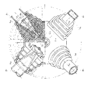
Figure 1 is a perspective view of the joint connection,
partially in cross section along the axis of one of the rods con-
nected so as to form the joint.
Figures 2 to 4 show cross sections through various em-
bodiments of a detail of the joint connection on the line II-II
in Figure 1.
A joint connection comprises a metal casing 1 having a
convex central portion that is approximately the shape of a flat-
tened sphere. Step-like tapered projections 3 that taper down to
the openings 2 of the metal casing 1 extend in star form from the
central portion.
In the right-hand (not cross-sectioned) portion of Figure
1 an opening 2 for a rod 4 is in the form of a square section tube;
another opening 2 for a rod 4 is shown in the form of a circular
tube is also shown. An advantage of the joint connection according
-- 3 --
457~
to the present invention is that fact that the rods 4 need not be
of identical cross section. For example, diagonal rods can be
lighter than chord (main) rods.
The left-hand portion of Figure 1 shows two rods 4 joined
to form a connection, the axis of said rods lying in the plane of
the drawing. The filling in the metal casing is shown in the upper
part of the left-hand portion of Figure 1. This filling is not
shown in the lower part of the left-hand portion of Figure 1, and
the end section of the rod 4 installed at this point is not shown
in cross section.
It can be seen that the rods 4 end within the metal cas-
ing 1 with a positive form-locking end section that is necked
down. It can be seen from the sectional drawings of the necked
down end sections of the rods 4 in Figures 2 to 4 that the restrict-
ed diameter is formed by pleating the walls of the tubing, this
being done without any concomitant weakening of the tubing or
change in the area of its cross section.
In each necked down end section of the rods 4 there are
two opposing expander elements 5, 6 on opposite sides of the necked
down section. The necked down section matches the shape of the
expander elements 5, 6. The two expander elements 5, 6 can be
tightened down against each other longitudinally by means of a
compression element 7 that is in the form of a high tensile strength
bolt or a plurality of such bolts (Figure 4) within the end section
of the rod 4, so that they abut tightly against the inside wall
of the tube on the opposing ends of the necked down portion.
~1~8~57~:
In the top of the metal casing 1 there is a filler means
8 through which the metal casing can be filled with hardenable
filler material.