Sélection de la langue

Search

Sommaire du brevet 1284574 

Énoncé de désistement de responsabilité concernant l'information provenant de tiers

Une partie des informations de ce site Web a été fournie par des sources externes. Le gouvernement du Canada n'assume aucune responsabilité concernant la précision, l'actualité ou la fiabilité des informations fournies par les sources externes. Les utilisateurs qui désirent employer cette information devraient consulter directement la source des informations. Le contenu fourni par les sources externes n'est pas assujetti aux exigences sur les langues officielles, la protection des renseignements personnels et l'accessibilité.

Disponibilité de l'Abrégé et des Revendications

L'apparition de différences dans le texte et l'image des Revendications et de l'Abrégé dépend du moment auquel le document est publié. Les textes des Revendications et de l'Abrégé sont affichés :

  • lorsque la demande peut être examinée par le public;
  • lorsque le brevet est émis (délivrance).
(12) Brevet: (11) CA 1284574
(21) Numéro de la demande: 1284574
(54) Titre français: FERMETURE A GLISSIERES SEPARABLES
(54) Titre anglais: SEPARABLE SLIDE FASTENER
Statut: Durée expirée - après l'octroi
Données bibliographiques
(51) Classification internationale des brevets (CIB):
  • A44B 19/08 (2006.01)
  • A44B 19/34 (2006.01)
  • A44B 19/38 (2006.01)
(72) Inventeurs :
  • TSUBOKAWA, YOSHITOKI (Japon)
  • YAMAMOTO, NOBORU (Japon)
(73) Titulaires :
  • YKK CORPORATION
(71) Demandeurs :
  • YKK CORPORATION (Japon)
(74) Agent: GOWLING WLG (CANADA) LLP
(74) Co-agent:
(45) Délivré: 1991-06-04
(22) Date de dépôt: 1985-10-17
Licence disponible: S.O.
Cédé au domaine public: S.O.
(25) Langue des documents déposés: Anglais

Traité de coopération en matière de brevets (PCT): Non

(30) Données de priorité de la demande:
Numéro de la demande Pays / territoire Date
59-161250 (Japon) 1984-10-25

Abrégés

Abrégé anglais


ABSTRACT OF THE DISCLOSURE
A separable slide fastener includes a pair of stringer
tapes made of a pliable thread-free material such as non-
woven fabrics, a row of coupling elements on each stringer
tape, a separable end assembly connected to bottom end
portions of the stringer tapes, and reinforcement strips
extending longitudinally over at least one side of the
respective stringer tapes from the bottom end portions,
respectively. The reinforcement strips have a length greater
than that of the bottom end assembly, with the result that
portions of the stringer tape contiguous to the upper end of
the end assembly are prevented from being bent or stretched
even after repeated operation of the fastener.

Revendications

Note : Les revendications sont présentées dans la langue officielle dans laquelle elles ont été soumises.


The embodiments of the invention in which an exclusive
right or privilege is claimed are defined as follows:
1. A separable slide fastener comprising:
(a) a pair of stringer tapes made of a pliable thread-
free material;
(b) a respective row of coupling elements mounted on
each tape along an inner longitudinal edge thereof;
(c) a slider adapted to bring said rows of coupling
elements into and out of engagement;
(d) a separable end assembly secured to the stringer
tapes at ends thereof; and
(e) reinforcement strips respectively attached at
least to one side of said tapes along the inner longitudinal
edges thereof and having a length greater than that of said
end assembly, each said reinforcement strip extending at
least over the portion of the stringer tape which supports
said end assembly and an endmost coupling element located
next to said end assembly.
2. A separable slide fastener according to claim 1,
said reinforcement strips extending respectively along the
inner longitudinal edges of said stringer tapes over the
entire length of the fastener.
3. A separable slide fastener according to claim 1,
each of said reinforcement strips extending on both sides
of a corresponding one of the stringer tapes along the
inner longitudinal edge thereof through the entire length
of the fastener, and enveloping bottom end portions of the
tapes.
- 7 -

4. A separable slide fastener according to claim 1,
said reinforcement strips, measured when said rows of
coupling elements on the respective tapes are in a mutual
engagement, having a combined width which is greater than
at least the width of said end assembly.
5. A separable slide fastener according to claim 1,
further including reinforcement strips extending
transversely across and enveloping the bottom end portions
of said tapes in the region of said end assembly.
6. A separable slide fastener according to claim 1,
each of said reinforcement strips being made of an intimate
weave of synthetic fibers.
7. A separable slide fastener according to claim 1,
each of said reinforcement strips being mede of a knitted
taffeta.
8. A separable slide fastener according to claim 1,
each of said reinforcement strips being made of a film of
synthetic regins.
- 8 -

Description

Note : Les descriptions sont présentées dans la langue officielle dans laquelle elles ont été soumises.

~4~
BACRGROUND OF THE INVENTION
1. Field of the Invention:
This invention relates to a slide fastener and more
particularly to a separable type of slide fastener having a
separable bottom end connection.
2. Prior Art:
A variety of separable slide fasteners have been
proposed for use on articles such as rain coats, anoraks,
bags and the like. Such a separable fastener is provided
with a separable end assembly at one of its tape ends that
allows the fastener to split apart at that end for the
intended purpose. The end assembly takes the form of a pin
member on one stringer and a socket member on the other
stringer, both members being releasably interengageable to
couple the stringers. The ends of the stringer tapes which
are usually woven or knitted, are reinforced in the region
of the separable assembly with a suitable reinforcement
strip of fabric or plastic film so as to ensure firm
attachment of the fastener to the article and also to
facilitate the manipulation of the end assembly.
Difficulties were encountered with separable slide
fasteners having stringer tapes made of pliable thread-free
material such as nonwoven fabric, the tape ends being
reinforced only at the region of the separable end assembly
with the result that the portion of the tape immediately
adjoinning the upper end of the end assembly is prone to
bend and stretch upon repeated operation of the fastener,

457~
causing a malfunction of the coupling elements adjacent to
the end assembly and eventually a rupture of the chain of
coupling elements. Bending forces when applied repeatedly
to the tape portion bordering the end assembly would often
tear off the tape along that area.
SUMMARY OF THE INVENTION
It is therefore the primary object of the present
invention to provide a separable slide fastener having
stringer tapes made of thread-free materials which are
reinforced against rupture of the chain or coupling
elements or damage to the tape.
According to the invention, a separable slide
fastener comprises a pair of stringer tapes made of a
pliable thread-free material carrying on and along their
inner longitudinal edges a pair of rows of coupling
elements, a separable end assembly connected to the bottom
ends of the stringer tapes, and a reinforcement strip
attached at least to one side of each of the tapes along
the inner longitudinal edge thereof. The reinforcement
strip has a length greater than that of the end assembly
and extends at least over the portion of the stringer tape
which supports the end assembly an endmost coupling element
located next to the end assembly.
The foregoing and other objects and features of the
invention will be better understood from the following
description taken in connection with the accompanying
drawings which illustrate by way of example some preferred

4574
embodiments which the invention assume in practice. Like
reference numerals refer to like or corresponding parts
throughout the several views.
BRIEF DESCRIPTION OF THE DRAWINGS
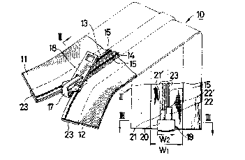
FIG. 1 is a perspective, partly plan view of a
separable slide fastener according to a preferred
embodiment of the invention
FIG. 2 is an enlarged cross-sectional view taken
along line II - II of FIG. l;
FIG. 3 is an enlarged cross-sectional view taken
along line III - III of FIG. l;
FIG. 4 is a plan view of a portion of a separable
fastener according to another embodiment of the invention;
FIG. 5 is a plan view of a portion of a separable
fastener according to a further embodiment of the
invention;
FIG. 6 is a cross-sectional view taken on enlarged
scale along line VI - VI and looking in the direction of
the arrow in FIG. 5; and
FIG. 7 is a cross-sectional view of a separable
fastener according to still another embodiment of the
invention.
DETAILED DESCRIPTION OF THE PREFERRED EMBODIMENTS
FIG. 1 shows a slide fastener 10 which is separable
at its bottom end. The fastener 10 comprises a pair of
stringer tapes 11 and 12 having confronting longitudinal
edges along which the opposed rows of coupling elements 13

4S74
and 14 are secured as by sewn seams 15. The rows of
coupling elements 13 and 14 are shown for purposes of
illustration to be in the form of a continuous helical coil
and are sewn through a pair of cords 16, 16 (FIG. 2) to the
respective tapes 11 and 12. A slider 17 is mounted astride
the confronting edges of the tapes 11 and 12 and it is
manipulated at its pull tab 18 to move slidably along the
rows of coupling elements 13 and 14 to close or open the
identical halves of the slide fastener 10 in the well known
manner.
The stringer tapes 11 and 12 are made of a
thread-free pliable sheet material such as for example
vinylchloride, polyester, polyamide and other suitable
synthetic resins, or nonwoven fabrics containing synthetic
fibers. The tapes 11 and 12 may be therefore conveniently
attached by ultrasonic or high-frequency welding to an
article made of for example a thermoplastic material.
Designated at 19 is a separable end assembly composed
of a socket member 20 including integrally formed stud 21
and attached on one stringer tape 11 and a pin member 22
attached on the other stringer tape 12, the socket and pin
members being releasably interengageable to couple the
fastener halves in a manner well known. The end assembly
19 may be clinched or injection-molded onto the bottom ends
of the stringer tapes 11, 12. The socket member 20 may
have a slider function, as is well knwon, so as to permit
the fastener to open from the reverse direction.

1~84574
In the embodiment shown in FIG. 1, there is provided
a reinforcement strip 23 attached to and extending all way
from one end to the other along the lower inner
longitudinal marginal surface of each of the tapes 11 and
12 which underlies the row of coupling elements 13, (14).
The reinforcement strip 23 is made of an intimate weave of
synthetic fibers, a knitted taffeta or a film of synthetic
resins. The reinforcement strips 23 when brought together
edge to edge have a combined width Wl at least greater than
the width W2 of the socket member 20, or preferably greater
than the track of the slider 17. The end assembly 19 is
mounted astride and envelops the bottom ends of the
stringer tapes 11, 12 at the region which includes the rows
of elements 13, 14 sewn seams 15, cords 16 and
reinforcement strips 23, as shown in FIG. 3. Importantly,
the reinforcement strips 23 each have a length greater than
that of the end assembly 19 and more specifically extend
along the inner confronting edges of the tapes 11, 12
beyond the exposed ends 21' and 22' of the stud 21 and the
pin 22, respectively that adjoin the rows of elements 13,
14, so as to protect the tape portions adjacent to the end
assembly 19 against damage which would otherwise result
from repeated handling of pin 22 and socket 20.
FIG. 4 illustrates a modified embodiment in which a
pair of reinforcement strips 23a, 23a are applied only to
the tape end portions where the end assembly 19 is located,
instead of the strips 23 extending along the entire length

~34574 -
of the fastener as embodied in FIG. 1.
FIGS. 5 and 6 illustrate a further modification which
is substantially the same as the embodiment of FIG. 1,
except that there is provided a reinforcement strip ~'
extending transversely of and wrapping around both sides of
the tape 13, (14) at the region of the end assembly 19, so
as to provide increased strength at that tape region.
FIG. 7 illustrates another embodiment in which a
reinforcement strip 23b wraps around both sides of each of
the tapes 11, 12 and extends along the inner longitudinal
edge of the tape either through the entire length of the
fastener or only at the bottom tape end where the end
assembly 1~ is located, the illustrated elements 13, 14
being of a discrete formation in which individual elements
are mounted astride of the confronting edges of the tapes.
Although various minor modifications may be suggested
by those versed in the art, it should be understood that we
wish to embody within the scope of the patent which may issue
hereon, all such embodiments as reasonably and properly
come within the scope of our contribution to the art.
6 --

Dessin représentatif
Une figure unique qui représente un dessin illustrant l'invention.
États administratifs

2024-08-01 : Dans le cadre de la transition vers les Brevets de nouvelle génération (BNG), la base de données sur les brevets canadiens (BDBC) contient désormais un Historique d'événement plus détaillé, qui reproduit le Journal des événements de notre nouvelle solution interne.

Veuillez noter que les événements débutant par « Inactive : » se réfèrent à des événements qui ne sont plus utilisés dans notre nouvelle solution interne.

Pour une meilleure compréhension de l'état de la demande ou brevet qui figure sur cette page, la rubrique Mise en garde , et les descriptions de Brevet , Historique d'événement , Taxes périodiques et Historique des paiements devraient être consultées.

Historique d'événement

Description Date
Inactive : Périmé (brevet sous l'ancienne loi) date de péremption possible la plus tardive 2008-06-04
Inactive : CIB de MCD 2006-03-11
Inactive : Lettre officielle 2000-01-18
Lettre envoyée 1999-06-04
Accordé par délivrance 1991-06-04

Historique d'abandonnement

Il n'y a pas d'historique d'abandonnement

Titulaires au dossier

Les titulaires actuels et antérieures au dossier sont affichés en ordre alphabétique.

Titulaires actuels au dossier
YKK CORPORATION
Titulaires antérieures au dossier
NOBORU YAMAMOTO
YOSHITOKI TSUBOKAWA
Les propriétaires antérieurs qui ne figurent pas dans la liste des « Propriétaires au dossier » apparaîtront dans d'autres documents au dossier.
Documents

Pour visionner les fichiers sélectionnés, entrer le code reCAPTCHA :


Pour visualiser une image, cliquer sur un lien dans la colonne description du document. Pour télécharger l'image (les images), cliquer l'une ou plusieurs cases à cocher dans la première colonne et ensuite cliquer sur le bouton "Télécharger sélection en format PDF (archive Zip)" ou le bouton "Télécharger sélection (en un fichier PDF fusionné)".

Liste des documents de brevet publiés et non publiés sur la BDBC .

Si vous avez des difficultés à accéder au contenu, veuillez communiquer avec le Centre de services à la clientèle au 1-866-997-1936, ou envoyer un courriel au Centre de service à la clientèle de l'OPIC.


Description du
Document 
Date
(aaaa-mm-jj) 
Nombre de pages   Taille de l'image (Ko) 
Abrégé 1993-10-20 1 18
Revendications 1993-10-20 2 50
Page couverture 1993-10-20 1 11
Dessins 1993-10-20 3 53
Description 1993-10-20 6 173
Dessin représentatif 2000-07-19 1 16
Taxes 1995-05-01 1 72
Taxes 1997-05-16 1 59
Taxes 1996-05-14 1 64
Taxes 1993-03-26 1 45
Taxes 1994-04-27 1 72