Note : Les descriptions sont présentées dans la langue officielle dans laquelle elles ont été soumises.
1~457~3
26157-9
l2 Field of the Inventior
l3 lhis inventioll relates to a kit including a
l4 leveling/~)lunlbing device and fastening straps for attachirlg
ttle device to an elongated workplece, such a.s a fence part,
16 to enable a user to level or plurllb such work~iece,.the kit
l7 being particularly useful for installillg fence posts and
l8 rails.
l9 ~ackground oL the Invention and Prior Art
2~ When a fence is being installed, it is desirable to
2l uosition the posts vertically and the rai.ls horizontalLy. 1.
22 l~llile this ca.n be done by eye, it is also comololl to use a
~3 simple car~enter's level that includes two spirit levels, one
2~ for determining a horizontal position and the other for
determining a vertical l)osition. The level is held against
~6 the post or rail by one hand while the other halld is used to I
27 adjust the rail or post to its proper uosition The disad-
28 vantage is that there are times when the user requires the
2Y use of both hallds and.must set down the level with the result
3~ that the rail or post can be moved without there being any
12~34578
26157-9
indication of the degree of horizontal or vertical movement.
Within the prior art there are many leveling devices
that provide indications of both horizontal and vertical
positions of an item being leveled or plumbed. U.S. patent
928,600 shows a simple carpenter's level having two vials at
right angles for indicating horizontal and vertical lines. The
device has a generally cubical body adapted to be held against
or set upon the workpiece.
U.S. patent 3,826,013 discloqes a device particularly
useful with rods, which device includes two bulls-eye levels.
The device uses right angle surfaces to position the device
against the workpiece and the device i3 manually held in place.
U.S. patents 2,757,458~ 3,664,754 and 4,295,279
describe strap on leveling devices attached to drills allowing
the user free use of both hands for drilling vertical and
horizontal holes. U.S. patent 3,832,782 shows a level having
magnets located near d~verging legs, which magnets allow the
level to be magnetically mounted upon a magnetically attracted
workpiece.
Perhap~ the closest prior art patent is U.S. patent
4,168,578 which shows a level having two right angular members,
the inner surfaces of which would be placed against a workpiece.
Several spirit levels are mounted on the external surfaces of
the memberq to indicate both horizontal and vertical positions.
Magnetic strips are attached to the inner surfaces allowing the
level to be attached to magnetically attractable workpieces to
free up the user's hands~ The patent also indicates that the
device can be secured to objects which are not metal "with a
pliable or elastic strap, cord, or tension
34S78
26157-9
spring wrapped arsund the object..." to free the user's hands.
As described below, the invention makes use of a well
known type of separable fastener of the type disclosed in V.S.
patent 3,009,235. Such fastener includes two pieces of base
material one of which has a multiplicity of loops and the other
of which ha~ a multiplicity of hooks. The two pieces can be
pressed together whereby the hook~ and loops interengage and
hold the two pieces together along with whatever the pieces are
fastened to. Several patents disclose the use of such a
fastener for diverse purposes. U.S. patent 3,321,068 uses the
fastener to support a thermometer. U.S. patent 3,358,141 uses
straps of the material to fasten a child to a board to
immobilize the child. U.S. patent 3,387,341 uses such a
fastener to support a pen or pencil.
Summary of the Invention
One of the object~ of the invention is to provide a
kit containing a leveling/plumbing device and ~traps for
attaching the device to fence posts and rails so a~ to free the
hands of the user and facilitate the rapid positioning of such
workpieces.
Another object is to provide a leveling/plumbing
device that can be readily attached to fence posts and rails of
diver3e cross ~ectional shapes including square, rectangular or
round shapes, and of any material quch as wood, plastic and both
magnetic and non-magnetic metals.
A further object is to provide a leveling/plumbing
device that is lightweight ~or ease of use and is rugged and
dimensionally stable for prolonged use.
Still another object is to provide a kit containing a
leveling/plumbing device and straps for attaching the device
-- 3 --
1~457~3
26157-9
to a workpiece, the strap~ being readily attachable and
detachable to facilitate the rapid erection of a fence including
both posts and rail~.
A still further object is to provide a cheap, simple,
rugged leveling/plumbing device that effectively allows work-
pieces such as fence posts and rails to be leveled and plumbed.
sriefly~ the invention comprise~ a kit having a
leveling/plumbing device and two straps. The device has an
elongated rigid body provided with two parallel positioning or
aligning edges or surfaces. The edges are engageable with a
workpiece to position the device parallel to the workpiece.
Connected to the device are two halves of separable fasteners of
the hook and loop type. The ~traps form the other halves of the
fasteners, each strap being long enough to allow the user to
wrap the strap around the workpiece and engage the free ends
with the fa3tener half on the device to attach the device to the
workpiece and free the hands of the user for leveling/plumbing
the workpiece. The device also has two spirit levels for
indicating horizontal and vertical orientations respectively.
In accordance with a broad aspect of the invention
there is provided a kit primarily adapted for plumbing or
leveling elongated fence members of different cross sectional
sizes and shapes, said kit comprising the combination of:
a leveling/plumbing device comprising a body provided
with first and second set~ of aligning edges, fastening means
mounted on said body, and level means mounted on ~aid body for
providing visual indications of the orientation of said device;
and strap means engageable with said fastening means
and adapted to be wrapped around a fence member to securably
releasably attach said device thereto with one ~et of ~aid
aligning edge~ abutting said member and orienting said device
- 4 -
5~3
26157-9
relative to such member, whereby a user has both hands free to
move and position such member while observing said leveling
means: ~aid leveling means comprising first and second levels
mounted on said body and respectively providing visual
indications of when said device is horizontal and vertical; said
body being thin walled, rigid, hollow, lightweight and elongated,
said body having a qidewall of arcuate cross section provided
with two transversely ~paced, parallel edges which form a first
set of thin aligning edge~ that are adapted to abut relatively
large size fence members at points on tranAversaly spaced lines
running longitudinally along such members, said body-further
having two end walls connected to said sidewall at different ends
of said body to form a rigid boxlike structure, said endwalls
each having a V-shaped edge extending transversely across said
body, said edge~ of said end walls forming a Aecond set of thin
aligning edges adapted to abut relatively small fence members at
two ~et~ of points spaced longitudinally along the lengths of
such fence members by a distance ~ubstantially equal to the
length of ~aid body.
Brief Description of the Drawings
Other object~ and advantages of the invention will be
apparent from the following deRcription taken in connection with
the accompanying drawings wherein:
Figure 1 i~ a top plan view of a kit constituting a
fir~t embodiment of the invention;
Figure 2 i~ a top plan view, on an enlarged scale, of
the leveling/plumbing device ~hown in Figure l;
Figure 3 is a ~ide elevational view of the device shown
- 4a -
,~ ",
457~3
26157-9
in Fig. 2;
Fig. 4 is an end elevational view of the device
shown in Fig. 2;
Fig. 5 is an end view illustrating how the
leveling/plumbing device of the invention is attachable to a
workpiece of round cross section;
Fig. 6 is a view similar to Fig. 5 showing how
the leveling/plumbing device is attachable to a workpiece of
rectangular cross section;
Fig. 7 is an enlarged, somewhat schematic view of
the separable fastener used in the invention;
Fig. 8 is a side elevational view, with portions
removed and partly in section, of a preferred form of a
leveling/plumbing device which is part of a second
embodiment of the invention;
Fig. 9 is a top plan view of the device shown in
Fig. 8;
Fig. 10 is a bottom plan view of the device shown
in Fig. 8;
Fig. 11 is an enlarged cross-sectional through a
central portion of the device shown in Fig. 8;
Fig. 12 is an enlarged end elevational view of the
device shown in Fig. 8;
Fig. 13 is a schematic end view illustrating how
the device shown in Fig. 8 abuts different size rounded
workpiece surfaces; and
Fig. 14 is a view similar to Fig. 13 showing
abutment with a workpiece having a straight edge.
Detailed Description of the ~nvention
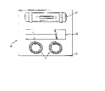
Referring now to the drawings, and first to Fig. 1,
345~3
the eInbo liment of the iIlventioll there shown coml)rises a
;~ Icit 1~ ouse(l in a box 11 or other package for distribution
:3 to the user. Kit ll) contains a leveling/plumbing device 12,
an adaptor 13, and two straps 14 showrl in coiled forms.
S (~uite obviously, the kit can be packaged in ottler ways.
6 With reference to l~igs. 2-4, device 1~ coInprises an
7 elongated body 16 of arcuate cross section, the lower portion
~ of wtIich is open to provide a pair of parallel ed~es 17 that ¦
Y are parallel to the axis of body 16. 'rhe body is foruIed fro
1() a rigid, plastic pipe having the lower portion removed to
11 forIn edges 17. I~ody I6 aLso has a central WilldOW 2U openirIg
12 upwar~ily, wheIl device 12 is in the horizontal position. I~
1:~ tubular spirit level 22 is mounted inside body 16 directly
I4 beneath window 2U so that all air bubble 24, slIown in dotted
I5 lines, and two centering lines 25 are visible to the user.
16 rwo end plates ;~6 are attached to the opposite ends of
I7 body 16 and form a somewhat box-like construction that
I3 strengtIIens body to form a rnore rigid structure. IiouIlted on
1~ plal:es 26 are two bulls-eye levels 2~ each oE WlliCIl has a
2() centeriIlg circle 3() useful in centering an air bubl~le 32.
;~1 Levels :~ face in opposite directions to enable device 12 to
2;~ I)e used at either end. Levels 2~ are used for the plumbing
23 function, i.e., to vertically align or position a workpiece.
24 'Lwo fastener or mounting strips 34 are attached to body 16
2~ ancl extend around tlIe peripIIery near the ends of device 12.
26 ~;traps 14 and strips 34 form readily attachable,
27 readily detachable, separable fasteners an(i are of the type,
2~3 disclosed in the above-mentiorIed patent 3,l)U~,235, comprisin
2~ a multiplicity ot llooks interellgageable with a multiplicity
3() of loops. 'Lhe loops and hooks are formed on two halves and
57B
l the two l1alves are interchangeable. I~eferring to Fig. 7,
2 strap l4 comprises a backing material 4() having a multipli- ¦
:~ city of hooks 42 on one side thereof. ~trip 34 has backi
4 44 adhesively connected or bonded to body 16. A multiplicityI
5 of loops l~6 exten~ outwardly from backing 44. When hooks 42 ¦
6 and loops 46 are pressed together, they interlock with suf- ¦
7 ficient strength ~hat it is difficult to seyarate them by
pulling along the length of the backing material but will
Y readily separate when pulled perpendicularly away froln each
1U other. ~;traps l4 are long enougll to be wrapped around
11 device l2 and a workpiece.
l2 l~eferring to Fig. 5, device l2 is sl1own attached to a
1:~ round workplece 50 which may be, for example, a metal fence
14 post. When attached, device l2 extends along workpiece 5()
l5 with its axis parallel to the axis of workpiece 5t~. Edges l7
l6 engage the outer surface of tl1e workpiece and straps 14 are
l7 wrapped around device l2 and workpiece to secure theIn
l~ together. As shown, strap 14 is loIlger than l1ecessary and
19 has one end unattached. rl'he free et~d could be cut off if
12v desired but it provides a convenient handle to grip the
2l strap and separate the fastener.
2~ In l~ig. 6, workpiece 52 is of square cross section.~ ¦
23 Adaptor l3 has tt1e shape of an angle iron witll two Inutually
24 perpendicular flanges. Adaptor l3 is fitted over one corner
~5 of the workpiéce and device 12 has edges 17 abutting the
26 outer surfaces of adaptor 13. I)evice l2 is positioned so
~7 that edges l7 extend parallel to the edges of the workpiece.
~3 lhe corner of adaptor l3 fits into the bottoln opening of
2Y body 16 whicl1 opening is bounded on tlle sides by edges l7.
:~() In use, device l2 is first positioned either in
-7-
457~ ~
¦ 1 contact Wit~l a rounded workpiece or with adaptor 1:~, and the
;~ two straps 14 are at~acIIed at one end to strips 34, wrappecl
:~ around the workpiece and theIl attached at the other end to
4 strips :34. ()nce attached, the user is free to use both hands;
for tlIe purpose of positioning the workpiece. L)evice 12 can I
G tI~en be cletaclIed siInply by relnoving straps I4.
7 l~eferring IIOW to l;~igs. 8-11, plwnL)ing/levelirlg deviceI
6() coInprises a rigid, hollow, lightweight body 62 molded froIn
~1 polystyreIle havirIg a high impact strengtlI. 13ody 62 has an
1() outer shell colnyrising two end walls 64 and 66 and a central
11 portion 68 of U-shaped cross section. A longitudinal rib 7~) 1
I2 extends through the interior of body 62 between end walls 64 ¦
I3 and 6G. E'ive transverse ribs 72 extend across tlle interior
I4 of tIle body between the sides of portion 68 and rib 7(). I~ibs¦
I5 7l) and 72 are joined to and merge with central portion ~ to ¦
16 strengtllen body 62 and forTn a cellular interior.
I7 l~ody 62 has a flat recessed surface 74 wIIich faces
I8 outwardly froln tlIe central portion and Llas a seInicylindrical
¦1Y recess 76 in~:o whicIl a tul7ular spirit level 78 is glued in
2~ place. 'rhe axis of level 78 is parallel to ttle axis of
¦~1 device 6(). l~ody 62 also has a slotted recess ~() in end wall ;~
~2 G6 into whiclI a bulls-eye spirit level 82 is glued in place.
;~ Level 82 operatively extends perpendicularly to the axis of
;~4 device 6(). Levels 7~ and 5~2 effectively lie at right angles
;~5 to each otIIer whereby level 78 is operative to indicate a
:~i horizoIltal orier-tation while level ~2 indicates a vertical
27 orientation. The outwardly facing surEaces of both levels
:~8 are set back or recessed relative to the adjacent outer sur- ¦
faces of body 62 to protect t~Ie levels froln being accidently
Iit.
457~ 1
1 'l`wo strips U4, the same as strips :34, are adllesively
ol~ded to body 6:~ at longitudillally spaced positiol~s and are
~ ell~ageal~Le wi~ll two straps 14 (not sllown in ligs. ~-ll L)u~
4 ~ig. 1) to form fasteners for selectively attachillg device t
to a workpiece in a Inanrler similar to that explained above.
~entral portioll 6~3 termitlates in two parallel,
7 laterally syaced surfaces or edges ~6 wllicl~ exten~ lo~lgitudi-
nally and are parallel to tlle axis of leveL )~. Iach of ribs
Y 7~ llas a shallow V-shaped surface 8~ whicll faces dowrlwardly
IU as viewed in l~ig. ll ancl lies slightly inwardly oi similarly
11 shape(J surfaces 9() tormed on the lower portions of end walls
1~ t)4 and 66. 'l'he centers of surfaces 9() have vertices Y;~ use-
1:i ful in aligning workpieces llaving straight corners or edges.
l4 ~urfaces Y() yrovide the prilnary alignillg or bearillg surfaces
15 for abutting circular workpieces 94 (Fig. l:~) of smaller
l6 diameters and edges ~36 form aligning edges for larger
l7 diameter workpieces Y6. Workpiece 98 (Fig. l4) having a flat
l8 surface provicled witll a straight corner or eclge, can be
19 aligned by wedging the eclge into vertex 9;~ Wittl the flat sur-
~U face of a workpiece abutting one side of surfaces 90. The
;~1 salne workpiece abutment action occurs at surface YU of end
wall 6~. ln each case, two aligning surfaces (surfaces 9U ~ol
:~3 end walls 64 and 66 or edges ~6) ellgage the workpiece at
;~4 spaced pOilltS or lines to provide stable alignlnellt of the
~5 device relative to a workpiece.
;~6 I)uring use, device 6U is attachable to a workpiece i
;~7 a Inanller silnilar to that described above for device l;~.
~ I)cvice ~U would first be fitted or abutted against a work-
;~Y piece so tLlat its axis lies parallel to tlle longitudinal
:~U axis of a workpiece and straps l4 wou1d be engaged with
4s78
ll
i¦l striys U4. 'Llle user can then view level 7~ to horizolltally
12 postiorl tlle workpiece or view level ~2 to vertically positi~
i~ the workpiece.
4 While eacll device was designed prilnarily for use in
collstructitl~ a fellce of vertical posts and tlorizontal rails, I
¦16 it shoul~Fi be obvious that it can be used for other types an~ !
7 shapes of workpieces. It should also be obvious that without,
the straps, this device could be use~ on any flat surface fori
¦~ leveling horizorlta11y, the salne as a conventiolla1 level.
l;urther, each device can be attached to both maglletic and
~1 non-magrletic workpieces. It should also be apparent to those
~2 skilled in the art that charlges can be ~nade in the ~etails
i~ and arrangement of parts without departillg froln tlle spirit
i4 alld scope of the invelltion as defined in the appellded claims.¦
- 10 --