Sélection de la langue

Search

Sommaire du brevet 1284791 

Énoncé de désistement de responsabilité concernant l'information provenant de tiers

Une partie des informations de ce site Web a été fournie par des sources externes. Le gouvernement du Canada n'assume aucune responsabilité concernant la précision, l'actualité ou la fiabilité des informations fournies par les sources externes. Les utilisateurs qui désirent employer cette information devraient consulter directement la source des informations. Le contenu fourni par les sources externes n'est pas assujetti aux exigences sur les langues officielles, la protection des renseignements personnels et l'accessibilité.

Disponibilité de l'Abrégé et des Revendications

L'apparition de différences dans le texte et l'image des Revendications et de l'Abrégé dépend du moment auquel le document est publié. Les textes des Revendications et de l'Abrégé sont affichés :

  • lorsque la demande peut être examinée par le public;
  • lorsque le brevet est émis (délivrance).
(12) Brevet: (11) CA 1284791
(21) Numéro de la demande: 1284791
(54) Titre français: DISPOSITIF POUR MONTER UN PETIT TUBE SUR UN APPAREIL ADAPTE POUR INSTALLER UNE SERINGUE SUR UNE BOUTEILLE DE MEDICAMENTS
(54) Titre anglais: DEVICE FOR COUPLING A SMALL TUBE TO AN APPARATUS ADAPTED FOR FITTINGA SYRINGE TO A DRUG HOLDING BOTTLE
Statut: Périmé et au-delà du délai pour l’annulation
Données bibliographiques
(51) Classification internationale des brevets (CIB):
  • A61M 05/00 (2006.01)
  • A61M 39/14 (2006.01)
(72) Inventeurs :
  • VALENTINI, LUIGI (Italie)
  • COCCIA, MARIO (Italie)
(73) Titulaires :
  • FARMITALIA CARLO ERBA S.R.L.
(71) Demandeurs :
  • FARMITALIA CARLO ERBA S.R.L. (Italie)
(74) Agent: SMART & BIGGAR LP
(74) Co-agent:
(45) Délivré: 1991-06-11
(22) Date de dépôt: 1987-07-22
Licence disponible: S.O.
Cédé au domaine public: S.O.
(25) Langue des documents déposés: Anglais

Traité de coopération en matière de brevets (PCT): Non

(30) Données de priorité de la demande:
Numéro de la demande Pays / territoire Date
22647 B/86 (Italie) 1986-07-25

Abrégés

Abrégé anglais


ABSTRACT
A device is disclosed for easily and simply coupling to
the free end of a small tube mounted on a transfusion needle an
apparatus of the type used for coupling a syringe to a drug hold-
ing bottle. The device comprises a body having a passage with one
end coupled to the small tube. The other end of the passage is
closed by a plug. A collar shaped like the mouth of a conventional
drug bottle projects from the body. The collar axially extends
for a length greater than that of the collar of a conventional
bottle and a continuous annular recess is formed therein having
such a profile and arrangement as to allow for teeth projecting
from resilient prongs of the apparatus to be inserted and locked
therein.

Revendications

Note : Les revendications sont présentées dans la langue officielle dans laquelle elles ont été soumises.


THE EMBODIMENTS OF THE INVENTION IN WHICH AN EXCLUSIVE
PROPERTY OR PRIVILEGE IS CLAIMED ARE DEFINED AS FOLLOWS:
1. A device for coupling a tube to an apparatus for
coupling a syringe to a drug holding bottle, said device
comprising:
(a) a body having a first end, a second end, a
longitudinal axis, and an axial passageway extending from said
first end of said body to said second end of said body, said first
end of said body being adapted to be connected to a hollow tube
such that said axial passageway is in fluid communication with the
interior of said hollow tube, said body comprising a first at
least substantially cylindrical wall at said second end of said
body that is concentric to said longitudinal axis and that has an
external annular recess therein spaced from said second end of
said body; and
(b) a resilient plug mounted on said second end of said
body so as to close said axial passageway;
(c) said second end of said body comprising: (i) said
first at least substantially cylindrical wall; (ii) a first blind
recess that is within said first cylindrical wall, that is
concentric to said longitudinal axis, and that is open to said
second end of said body; and (iii) a lug the radially outer
surface of which defines one side of said blind first recess,
which is concentric to said longitudinal axis, and which contains
said axial passageway, the radially outer surface of said lug
which defines one side of said first blind recess being at least
substantially cylindrical.

2. A device as recited in Claim 1 wherein said first end of
said body comprises:
(a) a second at least substantially cylindrical wall
concentric to said longitudinal axis;
(b) a second blind recess that is within said second at
least substantially cylindrical wall, that is concentric to said
longitudinal axis, and that is open to said first end of said
body; and
(c) said lug, the radially outer surface of which
defines one side of said second blind recess, which is concentric
to said longitudinal axis, which extends axially beyond said
second at least substantially cylindrical wall, which contains
said axial passageway, and which decreases in diameter towards
said first end of said body.
3. A device as recited in Claim 2 wherein the radially
inner surface of said second blind recess is threaded.
4. A device as recited in Claim 2 wherein the radially
outer surface of said lug which defines one side of said second
blind recess is at least substantially conical.
5. A device as recited in Claim 1 and further comprising a
rigid disk:
(a) mounted on said first at least substantially
cylindrical wall and said lug;

(b) mounting said resilient plug; and
(c) closing said first blind recess.

Description

Note : Les descriptions sont présentées dans la langue officielle dans laquelle elles ont été soumises.

~8479~
.
``;
The GB Patent Application Serial No. 2,178,664A discloses
a device for coupling, under safe conditlons, one end of a drug
delivering small tube to an apparatus for coupling a syringe to
the drug holding bottle.
This device has its free end, that is, its end which is
to be coupled to the mentioned apparatus, substantially the form
of a body shapea lik~ the mouth of a conventional bottle of the
type used for holding a drug. From the body three or more longi-
tudinal fins project, said fins having an even flat longitudinal
outer profile and operating for assuring an a~ial insertion of
the mentioned free end of the device and a firm holding of this
device in the seat of the apparatus whereon the drug holding
syringe is mounted.
As stated in the above mentioned Patent Application,
the apparatus to be coupled to the syringe is provided with three
or more resilient prongs each of which bears a tooth which, as the
free end of the device is inserted in-to said apparatus seat,
engages the device free edge:such an apparatus is disclosed in the
United States Patent 4,576,211.
It has been found that the provision of the longitudinal
fins projecting from the body (and the radially outermost longi-
tudinal peripheral edge of which is even) may cause latching pro-
blems if the longitudinal fins are arranged in front of the teeth
of the apparatus : in fact, if the device is not arranged with its
fins disengaged from the apparatus teeth, then the device can not
be coupled to the apparatus, and the user may not notice the draw-

~L~84~79~
back, with the very dangerous consequence (it should be remembered
that many drugs are very toxic) that the device may detach from
the apparatus during the drug delivering step.
Thus, the main object of the present invention is to
provide a device of the above-mentioned type which may be easily
inserted into the seat of the apparatus, whiLe holding always a
longitudinal orientatlon during the insertion, and being always
firmly held in the seat, in an oscillation free condition, and
being firmly engaged by the teeth projecting from the apparatus,
as soon as the device is introduced into said seat.
According to the invention there is provided a device
for coupling a tube to an apparatus for coupling a syringe to a
drug holding bottle, said device comprising:
(a) a body having a first end, a second end, a
longitudinal axis, and an axial passageway extending from said
first end of said body to said second end of said body, said first
end of said body being adapted to be connected to a hollow tube
such that said axial passageway is in fluid communication with the
interior of said hollow tube, said body comprising a first at
least substantially cylindrical wall at said second end of said
body that is concentric to said longitudinal axis and that has an
external annular recess therein spaced from said second end of
said body; and
(b) a resilient plug mounted on said second end of said
body so as to close said axial passageway;
(c) said second end of said body comprisingo (i) said
first at least substantially cylindrical wall; (ii) a first blind
~.

L2~7~
recess that is wiihin said firs-t cylindrical wall, that is
concentric to said longitudinal axis, and that is open to said
second end of said body; and (iii) a lug the radially outer
surface of which defines one side of said blind first recess,
which is concentric to said longitudinal axis, and which contains
said axial passageway, the radially outer surEace oE .said lug
which defines one side of said first blind recess being at least
substantially cylindrical.
In order to better understand the structure and
character-
2a

``` 3L~3~7~L
istics of the subject device, a preferred embodiment thereof will
be disclosed hereinafter, with reference to the accompanying
drawing, where:
Figure ]. is a perspective view o~ the device according
to the present invention;;and
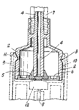
Figure 2 is an en~arged scale cross-sectional view of the
device.
The device shown in the drawing comprises a shaped body
1 which is laterally delimited by a cylindrical wall 2 on the outer
surface of which there is formed an annular recess 3. Inside the
cylindrical wall 2 and along its axis, a passage-defining member
4 extends, defining a passage which is open at the top ena thereof
(as shown in the drawing), while at the other end thereof it is
closed by a resilient plug 5 (made of rubber or like material)
which is held firmly pressed on the free end of the member 4 by
means of a small rigid holding dlsc 6 affixed to the cylindrical
wall 2.
In a known way, on the free projecting end of the hollow
member 4 there is mounted one end of a resilient small tube (a
portion of which has been shown by the dashed line 7 in Figure 2)
to the other end of which an epicranial needle may be coupled for
the transfusion, into a vein of a patient, of a drug which is
injected into the passage of the member 4 by a needle 8 (which is
shown in phantom in Figure 2) mounted on a syringe (not shown).
The needle 8 is included in an apparatus li~.e that dis-
closed in the United ~tates Patent 4,576,211. At the lower portion
-- 3

of Figure 2 therè is shown, by a dashed line, that end portion of
this apparatus where a seat is formed for housing and holding the
device according to the present invention.
It should briefly be remembered that this seat is defined
by a tubular cylindrical wall 9 within which resilient prongs 10
extend, a tooth 11 projecting inwardly from each said prony
At the center of the apparatus seat a rubber or the like
pad 12 projects which, as the subject device is locked in said
: seat, as is schematically shown in Figure 2, is held firmly
pressed against the resilient plug.5.
The operation of the needle 8 bearing apparatus will be
not disclosed herein, since it has been clearly illustrated in the
above-mentioned United States Patent 4,576,211.
A main feature of the device according to the present
invention is that the cylindrical wall 2 has a cross-section equal
or analogous to the cross-section of the collar of a conventional
drug holding bottle; that the mentioned cylindrical wall axially
extends for a length greater than the depth of the housing seat
defined by the cylindrical wall 9 and the resilient prongs 10 of
the apparatus, as is clearly shown in Figure 2, and that the an~ular
recess 3 is so arranged and shaped that, as the device is coupled
to the apparatus, the teeth 11 of the resilient prongs 10 will
always enter said annular recess to be locked therein.
This means that as soon as the device is inserted into
the seat of the apparatus and the resilient plug 5 is pressed
against the pad 12, the teeth 11 will enter the annular recess 3,

~34~
thereby flrmly engaging the device with the apparatus.
The ~act that the cylindrical wall 2 axially extends in
the indicated way is also an essential eature, since in this
way a large resting area is provided for the outer surface of said
cylindrical wall ayainst the adjoining surface of the apparatus
seat : thus the device will form a nearly rigid body with the
apparatus, since it can not oscillate in said apparatus housing
seat.

Dessin représentatif
Une figure unique qui représente un dessin illustrant l'invention.
États administratifs

2024-08-01 : Dans le cadre de la transition vers les Brevets de nouvelle génération (BNG), la base de données sur les brevets canadiens (BDBC) contient désormais un Historique d'événement plus détaillé, qui reproduit le Journal des événements de notre nouvelle solution interne.

Veuillez noter que les événements débutant par « Inactive : » se réfèrent à des événements qui ne sont plus utilisés dans notre nouvelle solution interne.

Pour une meilleure compréhension de l'état de la demande ou brevet qui figure sur cette page, la rubrique Mise en garde , et les descriptions de Brevet , Historique d'événement , Taxes périodiques et Historique des paiements devraient être consultées.

Historique d'événement

Description Date
Inactive : CIB expirée 2023-01-01
Inactive : CIB de MCD 2006-03-11
Inactive : Demande ad hoc documentée 1994-06-11
Le délai pour l'annulation est expiré 1993-12-13
Lettre envoyée 1993-06-11
Accordé par délivrance 1991-06-11

Historique d'abandonnement

Il n'y a pas d'historique d'abandonnement

Titulaires au dossier

Les titulaires actuels et antérieures au dossier sont affichés en ordre alphabétique.

Titulaires actuels au dossier
FARMITALIA CARLO ERBA S.R.L.
Titulaires antérieures au dossier
LUIGI VALENTINI
MARIO COCCIA
Les propriétaires antérieurs qui ne figurent pas dans la liste des « Propriétaires au dossier » apparaîtront dans d'autres documents au dossier.
Documents

Pour visionner les fichiers sélectionnés, entrer le code reCAPTCHA :


Pour visualiser une image, cliquer sur un lien dans la colonne description du document. Pour télécharger l'image (les images), cliquer l'une ou plusieurs cases à cocher dans la première colonne et ensuite cliquer sur le bouton "Télécharger sélection en format PDF (archive Zip)" ou le bouton "Télécharger sélection (en un fichier PDF fusionné)".

Liste des documents de brevet publiés et non publiés sur la BDBC .

Si vous avez des difficultés à accéder au contenu, veuillez communiquer avec le Centre de services à la clientèle au 1-866-997-1936, ou envoyer un courriel au Centre de service à la clientèle de l'OPIC.


Description du
Document 
Date
(aaaa-mm-jj) 
Nombre de pages   Taille de l'image (Ko) 
Abrégé 1993-10-19 1 18
Revendications 1993-10-19 3 66
Dessins 1993-10-19 1 23
Description 1993-10-19 6 167
Dessin représentatif 2000-07-19 1 17