Sélection de la langue

Search

Sommaire du brevet 1285158 

Énoncé de désistement de responsabilité concernant l'information provenant de tiers

Une partie des informations de ce site Web a été fournie par des sources externes. Le gouvernement du Canada n'assume aucune responsabilité concernant la précision, l'actualité ou la fiabilité des informations fournies par les sources externes. Les utilisateurs qui désirent employer cette information devraient consulter directement la source des informations. Le contenu fourni par les sources externes n'est pas assujetti aux exigences sur les langues officielles, la protection des renseignements personnels et l'accessibilité.

Disponibilité de l'Abrégé et des Revendications

L'apparition de différences dans le texte et l'image des Revendications et de l'Abrégé dépend du moment auquel le document est publié. Les textes des Revendications et de l'Abrégé sont affichés :

  • lorsque la demande peut être examinée par le public;
  • lorsque le brevet est émis (délivrance).
(12) Brevet: (11) CA 1285158
(21) Numéro de la demande: 1285158
(54) Titre français: MECANISME DE DETENTE DE L'ARBRE POUR DISPOSITIF DE TEMPORISATION
(54) Titre anglais: SHAFT DETENT ASSEMBLY FOR A TIMING MECHANISM
Statut: Périmé et au-delà du délai pour l’annulation
Données bibliographiques
(51) Classification internationale des brevets (CIB):
  • F16H 53/00 (2006.01)
  • F16D 11/14 (2006.01)
  • H01H 15/06 (2006.01)
  • H01H 43/10 (2006.01)
(72) Inventeurs :
  • EDER, ROBERT L. (Etats-Unis d'Amérique)
(73) Titulaires :
  • EMERSON ELECTRIC CO.
(71) Demandeurs :
  • EMERSON ELECTRIC CO. (Etats-Unis d'Amérique)
(74) Agent: BORDEN LADNER GERVAIS LLP
(74) Co-agent:
(45) Délivré: 1991-06-25
(22) Date de dépôt: 1987-11-04
Licence disponible: S.O.
Cédé au domaine public: S.O.
(25) Langue des documents déposés: Anglais

Traité de coopération en matière de brevets (PCT): Non

(30) Données de priorité de la demande:
Numéro de la demande Pays / territoire Date
07/026,454 (Etats-Unis d'Amérique) 1987-03-17

Abrégés

Abrégé anglais


SHAFT DETENT ASSEMBLY FOR A TIMING MECHANISM
ABSTRACT OF THE DISCLOSURE
A detent assembly positively locates an axial displaceable cam
carrying shaft to one of two positions. The assembly includes spring
fingers which extend into a bore of a bearing support for the shaft and
cooperating grooves in the shaft.

Revendications

Note : Les revendications sont présentées dans la langue officielle dans laquelle elles ont été soumises.


The embodiments of the invention in which an
exclusive property or privilege is claimed are defined
as follows:-
1. A timing mechanism comprising a support,
a camstack having a hollow hub, said camstack
rotatably mounted in said support;
first switch means engaging said camstack to be
actuated thereby;
a bearing rotatably journalled in said support;
a shaft rotatably mounted within said camstack
and in said bearing and axially movable between a
first position and a second position;
clutch means for engaging and disengaging said
shaft and said camstack when said shaft is moved
between said positions;
detent means for locating said shaft in either
said first position or said second position, said
detent means comprising a plurality of grooves formed
in said shaft and spring fingers integrally formed
with said bearing and engaging one of said grooves
when said shaft is in said first position and another
of said grooves when said shaft is in said second
position.
2. A timing mechanism according to claim 1 wherein
said spring fingers include lugs for engaging said
grooves.
3. A timing mechanism according to claim 1 wherein
said bearing has a bore in it and said spring fingers
extend into said bore of said bearing.
4. A timing mechanism according to claim 1 and
further including second switch means controlling
power to said timing mechanism, a switch actuator

means on said shaft for selectively actuating said
second switch means, and coupling means for coupling
said actuator means and said bearing to said camstack.
5. A timing mechanism according to claim 4 wherein
said coupling means includes tangs extending
lengthwise from said hollow hub, said bearing includes
a cup shaped portion having ribs therein dividing said
cup shaped portion into compartments, and said tangs
extend into said compartments.

Description

Note : Les descriptions sont présentées dans la langue officielle dans laquelle elles ont été soumises.

12~5~58
The present invention relates to a detent
assembly for a timing mechanism and more particularly
to such an assembly that is operable in conjunction
with an axially displaceable cam carrying shaft to
provide a positive location of the shaft.
Timing mechanisms for appliances such as
washing machines generally employ a timing cam or
camstack which is advanced in a step-by-step manner to
program the appliance. The camstack can be manually
se-t through a clutch by the appliance operator;
however, during such manual setting all power to the
timing mechanism should be shut off. In order to
accomplish -this, the shaft is manually axially
displaced to open a line switch and shut off the power
during manual setting of the cams-tack. The present
invention pertains to a detent assembly which insures
a positive location of the shaft and which has a
minimum number of parts and thus is easier and less
expensive to produce.
According to a broad aspect of the present
invention, there is provided a timing mechanism which
comprises a support and a camstack having a hollow
hub. The camstack is rotatably mounted in the
support. First switch means engages the camstack to
be actuated thereby. A bearing is rotatably
journalled in the support. A shaft is rotatably
mounted within the camstack and in the bearing and
axially movable between a first position and a second
position. Clutch means is provided for engaging and
disengaging the shaft and the camstack when the shaft
is moved between the said positions. Detent means is
provided for locating the shaft in either the first
position or the second position. The detent means
comprises a plurality of grooves formed in the shaft
and spring fingers integrally formed with the bearing
:h - 1
-
: ,. - - ':: '
. . . ~
. .
.. . .

128515~3
and engaging one of the grooves when the shaft is in
the first position and another of the grooves when the
shaft is in the second position.
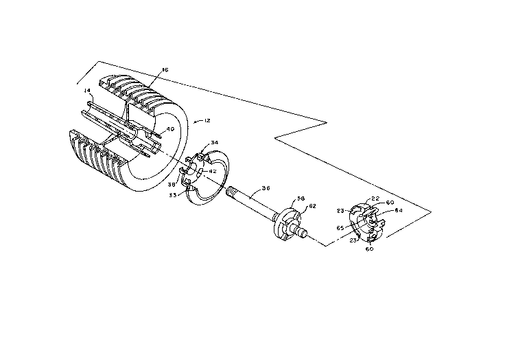
Figure 1 is an exploded view of a camstack
employing -the detent assembly of the invention.
Figures 2 and 3 are sections of a portion of a
timing mechanism using the detent assembly of Figure 1
in the assembly's two different operating modes.
Referring now to the clrawings, there is shown a
timing mechanism 10 employing the invention. Timing
mechanism 10, in general, includes
- la -
, : :
-~ .

~:85158
a camstack 12 having a hollow hub portion 14 with a plurality of cam
lobes on cam tracks 16 extending about the hub portion. A plurality of
electrical switches 18 (one shown) engage the camstack to be opened and
closed thereby. The switches open and close electrical circuits to an
appliance in a manner well known in the art. A shaft 36 extends
through the hub portion and is journalled for rotation within the hub
and a bearing support 22. Bearing support 22 is carried in end plate
24 while hub 14 is journalled in end plate 26. Shaft 36 is axially
movable to one of two positions. The camstack is coupled to a motor 28
for power driven rotation through gears 30 and 32, gear 32 being
provided integral with the camstack.
A line switch actuator 34 is independently rotatably carried on
shaft 36. It is "snugly" held on the shaft through a plurality of
spring fingers 38 and is coupled to camstack 12 through tangs 40 which
extend lengthwise from hollow hub 14 through openings 42 provided in
actuator 34. Tangs 40 also extend through openings 23 to couple
bearing support 22 to camstack 12. Actuator 34 includes ring 33 having
an outer rim 44 and a ramp surface 46. As will be hereinafter
discussed, an axial movement of shaft 36 causes the actuator 34 to open
or close line switch 48 through a slider 50 and a follower 52 carried
by movable blade 54 of the switch. Slider 50 is mounted in a slot (not
shown) of end plate 24.
Clutch means 56 includes a toothed member 58 fixedly carried on
shaft 36 and teeth 60 carried on bearing support 22. Engagement of
teeth 62 carried on toothed member 58 with teeth 6~ permits camstack to
be manually set in~a manner to be described.
In accordance with the invention a detent assembly 63 is provided
which limits the axial movement of shaft 36 and thus provides a
positive location of the shaft. Detent assembly 63 includes a
plurality of spring fingers 64 extending into bore 65 of bearing
support 22 and grooves 66 and 68 in shaft 36. The spring finger
selectively engages the grooves and positively holds the shaft in place
with through lugs 67 extending from the distal ends of the fingers.
The operation of the clutch, line switch and detent assembly can
now be described. Referring to Figure 2, the operating mode of the
.

~ 5~L5 8
timing mechanism is shown without electrical power being applied to the
timing mechanism. Shaft 36 has been axially moved outward in the
direction of arrow A to move slider 50 up ramp 46 to the top of rim 44
to force switch blade 54 down and open switch 48. Teeth 6Q and 62 are
engaged to permit the appliance operator to manually set the camstack
through shaft 36. Fingers 64 have engaged groove 66 to arrive at the
proper axial movement of the shaft.
In Figure 3, shaft 36 has been indexed in the direction of arrow B
along with actuator 34 to permit slider 46 to move down ramp 46 to
close line switch 48 and apply electrical power to the timing
mechanism. Teeth 60 and 62 are disengaged to prevent manual rotation
of camstack 12 with power applied to the timing mechanism. Camstack 12
is rotated by motor 28 through gears 35 and 32. Actuator 34, bearing
support 22, tooth member 5~ as well as shaft 36 are rotating with the
camstack. Fingers 64 have engaged groove 68 to assure the proper axial
movement of the shaft.
`
`

Dessin représentatif
Une figure unique qui représente un dessin illustrant l'invention.
États administratifs

2024-08-01 : Dans le cadre de la transition vers les Brevets de nouvelle génération (BNG), la base de données sur les brevets canadiens (BDBC) contient désormais un Historique d'événement plus détaillé, qui reproduit le Journal des événements de notre nouvelle solution interne.

Veuillez noter que les événements débutant par « Inactive : » se réfèrent à des événements qui ne sont plus utilisés dans notre nouvelle solution interne.

Pour une meilleure compréhension de l'état de la demande ou brevet qui figure sur cette page, la rubrique Mise en garde , et les descriptions de Brevet , Historique d'événement , Taxes périodiques et Historique des paiements devraient être consultées.

Historique d'événement

Description Date
Le délai pour l'annulation est expiré 2006-06-27
Inactive : CIB de MCD 2006-03-11
Lettre envoyée 2005-06-27
Lettre envoyée 2003-06-17
Lettre envoyée 2003-05-29
Lettre envoyée 2002-07-24
Lettre envoyée 2002-05-21
Exigences relatives à la révocation de la nomination d'un agent - jugée conforme 1999-09-17
Exigences relatives à la nomination d'un agent - jugée conforme 1999-09-17
Lettre envoyée 1998-07-15
Accordé par délivrance 1991-06-25

Historique d'abandonnement

Il n'y a pas d'historique d'abandonnement

Historique des taxes

Type de taxes Anniversaire Échéance Date payée
TM (catégorie 1, 7e anniv.) - générale 1998-06-25 1998-03-11
TM (catégorie 1, 8e anniv.) - générale 1999-06-25 1998-06-10
TM (catégorie 1, 9e anniv.) - générale 2000-06-26 2000-05-08
TM (catégorie 1, 10e anniv.) - générale 2001-06-26 2001-06-22
TM (catégorie 1, 11e anniv.) - générale 2002-06-25 2002-03-20
TM (catégorie 1, 13e anniv.) - générale 2004-06-25 2002-03-20
TM (catégorie 1, 12e anniv.) - générale 2003-06-25 2002-05-02
Titulaires au dossier

Les titulaires actuels et antérieures au dossier sont affichés en ordre alphabétique.

Titulaires actuels au dossier
EMERSON ELECTRIC CO.
Titulaires antérieures au dossier
ROBERT L. EDER
Les propriétaires antérieurs qui ne figurent pas dans la liste des « Propriétaires au dossier » apparaîtront dans d'autres documents au dossier.
Documents

Pour visionner les fichiers sélectionnés, entrer le code reCAPTCHA :


Pour visualiser une image, cliquer sur un lien dans la colonne description du document. Pour télécharger l'image (les images), cliquer l'une ou plusieurs cases à cocher dans la première colonne et ensuite cliquer sur le bouton "Télécharger sélection en format PDF (archive Zip)" ou le bouton "Télécharger sélection (en un fichier PDF fusionné)".

Liste des documents de brevet publiés et non publiés sur la BDBC .

Si vous avez des difficultés à accéder au contenu, veuillez communiquer avec le Centre de services à la clientèle au 1-866-997-1936, ou envoyer un courriel au Centre de service à la clientèle de l'OPIC.


Description du
Document 
Date
(aaaa-mm-jj) 
Nombre de pages   Taille de l'image (Ko) 
Abrégé 1993-10-19 1 10
Revendications 1993-10-19 2 57
Dessins 1993-10-19 2 55
Description 1993-10-19 4 126
Dessin représentatif 2001-07-15 1 19
Avis concernant la taxe de maintien 2005-08-21 1 172
Correspondance 2003-05-28 1 8
Correspondance 2003-06-16 1 11
Correspondance 1998-07-14 1 12
Correspondance 2002-07-23 1 16
Correspondance 2002-05-20 1 13
Taxes 1997-04-14 1 71
Taxes 1995-05-28 1 51
Taxes 1996-03-07 1 57
Taxes 1994-01-06 1 63
Taxes 1993-01-31 1 53