Sélection de la langue

Search

Sommaire du brevet 1285454 

Énoncé de désistement de responsabilité concernant l'information provenant de tiers

Une partie des informations de ce site Web a été fournie par des sources externes. Le gouvernement du Canada n'assume aucune responsabilité concernant la précision, l'actualité ou la fiabilité des informations fournies par les sources externes. Les utilisateurs qui désirent employer cette information devraient consulter directement la source des informations. Le contenu fourni par les sources externes n'est pas assujetti aux exigences sur les langues officielles, la protection des renseignements personnels et l'accessibilité.

Disponibilité de l'Abrégé et des Revendications

L'apparition de différences dans le texte et l'image des Revendications et de l'Abrégé dépend du moment auquel le document est publié. Les textes des Revendications et de l'Abrégé sont affichés :

  • lorsque la demande peut être examinée par le public;
  • lorsque le brevet est émis (délivrance).
(12) Brevet: (11) CA 1285454
(21) Numéro de la demande: 1285454
(54) Titre français: SOUPAPE DE DETENTE
(54) Titre anglais: PRESSURE RELIEF VALVE
Statut: Durée expirée - après l'octroi
Données bibliographiques
(51) Classification internationale des brevets (CIB):
  • F16K 17/00 (2006.01)
  • F16K 17/40 (2006.01)
(72) Inventeurs :
  • TAYLOR, JULIAN S. (Etats-Unis d'Amérique)
(73) Titulaires :
  • JULIAN S. TAYLOR
(71) Demandeurs :
(74) Agent: BORDEN LADNER GERVAIS LLP
(74) Co-agent:
(45) Délivré: 1991-07-02
(22) Date de dépôt: 1987-11-12
Licence disponible: S.O.
Cédé au domaine public: S.O.
(25) Langue des documents déposés: Anglais

Traité de coopération en matière de brevets (PCT): Non

(30) Données de priorité de la demande:
Numéro de la demande Pays / territoire Date
06/931,305 (Etats-Unis d'Amérique) 1986-11-17

Abrégés

Abrégé anglais


Abstract
A valve body having a lateral exhaust port is provided with
a valve movable toward and away from a fluid inlet sealing face
at its pressure connected end and guided by a valve stem project-
ing through the other end of the body and terminating in spaced
relation with respect to a cap closing the end of the body oppo-
site its inlet port. An axially collapsible member is axially
interposed between the downstream end of the valve stem and the
cap to normally maintain the the flow passageway between the
ports closed. Excessive fluid pressure against the valve at the
inlet port collapses the collapsible member, unseats the valve
and opens the fluid discharge passageway.

Revendications

Note : Les revendications sont présentées dans la langue officielle dans laquelle elles ont été soumises.


The embodiments of the invention in which an exclusive
property or privilege is claimed are defined as follows:
1. A pressure relief valve, comprising a valve body having
an axial bore forming an inlet port at one end and having a lat-
eral bore intersecting the axial bore for forming an outlet port
and a flow passageway between the ports, a valve seat in the in-
let end portion of the flow passageway, valve means slidable in
the axial bore and normally sealed with said seat for closing the
flow passageway, valve cap means for closing the end of the axial
bore opposite the inlet port, and, collapsible means including an
elongated rigid member coaxially interposed between said valve
cap means and said valve means for normally maintaining said flow
passageway closed.
2. The relief valve according to claim 1 in which the axial
bore in said body opposite the inlet port is diametrically en-
larged to permit lateral collapsing movement of said collapsible
means.
3. The relief valve according to claim 1 in which the col-
lapsible member comprises an elongated pin.
4. The relief valve according to claim 1 in which the valve
cap means further includes a valve cap, and, a cap plate inter-
posed between said cap and the collapsible means.
5. The relief valve according to claim 4 in which the valve
means and cap plate are axially bored centrally to form confront-
ing cylindrical sockets axially aligned with the valve body inlet
for closely nesting respective end portions of said pin.
-6-

Description

Note : Les descriptions sont présentées dans la langue officielle dans laquelle elles ont été soumises.

lZ~3S454
The present invention relates to fluid pressure relief
valves.
Relief valves are conventionally used in fluid pressure
systems for the purpose of protecting the fluid pressure gene-
rating equipment. In the event of equipment malfunction or clos-
ing an external valve in error or excessive pressure, the relief
valve is biased to an open fluid discharge position enabling the
operators to correct the malfunction without damage to the equip-
ment. This invention provides such a relief valve.
Fluid pressure relief valves presently in use generally
relate to valve structure which includes a valve stem or mandrel
moved longitudinally in response to predetermined fluid pressure
which shears a pin or ruptures a frangible disk, or the like. The
pressure setting in which these valves open to release such pres-
sure is predetermined by the pressure necessary to shear the
shear pin or rupture the frangible disk. The pressure at which
such a valve opens is thus predetermined by the known rating or
shearing force required to shear a pin or rupture a frangible
disk of predetermined thickness.
~0 Shear type valves are dangerous in that they can be ren-
dered inoperative by a workman, tired of resetting the valve,
putting more than one shear pin or nail through the shear bar on
one type safety relief valve or using extra strong metal, such as
an Allen wrench through the shear stem in another type shear re-
lief valve. Rupture disks have the disadvantage of being diffi-
cult to service in the field after rupture.
Rather than a frangible disk or shear pin this invention
provides a relief valve in which fluid pressure axially col-
lapses a single strand wire-like pin, shaft or tube. ~othing in
the line has to be disturbed during resetting as the piston seal
can be reset external to the valve cavity.
In the drawings which illustrate embodiments of the inven-
tion.
-1-

128S45~
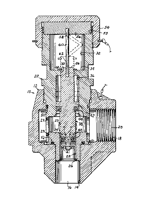
Figure 1 is a vertical cross sectional view of the relief
valve and illustrating its pressure opened position by dotted
lines;
Figure 2 is a fragmentary elevational view, to a larger
scale, of the collapsible rod, per se; and,
Figures 3, 4 and 5 are longitudinal cross section views of
alternative embodiments of the collapsible rod.
The reference numeral 10 indicates a valve which is elon-
gated tubular in general configuration comprising a body 12 hav-
ing an axial bore 14 forming a fluid inlet port 16 and a lateralbore 18 intersecting the axial bore and forming an outlet port
20 and a fluid passageway between the ports. Obviously the inlet
end portion of the valve body may be provided with conventional
internal or external threads or a flanged end, neither being
shown. At its end portion beyond its intersection with the later-
al bore, the axial bore is counterbored for receiving one end
portion of a valve cage 22 which axially projects beyond the
valve body opposite the valve inlet port. The inward end of the
cage is provided with a plurality of wall ports 23 and axially
supports a valve seat 24 having a sleeve-like portion 26 periph-
erally nested by the wall forming the inlet port. The bore of the
sleeve portion forms a cylindrical valve sealing surface 28. The
outer wall of the valve 24 is joined to the inner wall of the
cage by a retaining wire 29. The other end portion of the cage is
axially bored, as at 30, and counterbored, as at 32, on a diame-
ter relatively large when compared with the bore 30 or the inlet
port 16, defining a counterbore end surface or shoulder 34 for
the purposes presently explained.
Upstream a selected distance from the counterbore 32 the
cage is further counterbored, as at 36, on as selected diameter
for slidably receiving a valve means 38. The valve means 38 is
generally elongated cylindrical with its upstream end portion
diametrically reduced and surrounded by a primary sealing ring

~.285~54
40, secured by nut means 41, for sealing with the valve seat 28.
Intermediate its ends and within the counterbore 36, the valve 38
is provided with a diametrically enlarged portion 42 slidable in
the counterbore 36 and supporting secondary sealing means 44 seal-
ing with the wall forming the counterbore 36. The end portion 46of the valve stem is slidable in the cage bore 30 and movement of
the valve means 38 toward the inlet port 16 is stopped by a snap
ring 48 secured to the valve stem 46 adjacent the shoulder 34.
Other seals, such as the O-rings 50 and 52, respectively,
seal the periphery of the cage and valve seat with the valve
body.
The end portion of the cage opposite the inlet port 16 is
externally threaded for receiving a valve body cap 54. This end
surface of the cage wall is coaxially counterbored a selected
depth to define an annular shoulder 55. A cap plate 56 is coaxi-
ally nested by the shoulder 55 and is interposed between the
valve cap and adjacent end of the cage. The plate 56 is provided
with an axial socket 58. A pressure collapsible member, such as a
rod 60, is interposed between the cap plate and adjacent end of
the valve stem 46, the valve stem 46 being similarly axially bor-
ed to form a socket 62. The sockets 58 and 62 nests respective
end portions of the member 60. The rod 60, preferably formed from
metal, may be a common nail or a length of metallic tubing. The
rod 60 is usually referred to as a pin and its diameter, length
and axial compressive resistance is predetermined for controlling
a predetermined fluid pressure against the valve at the inlet
port.
As illustrated by Fig. 2, the pin 60 is right circular cy-
lindrical, but may be of other transverse cross section, if de-
sired. The respective ends of the pin are chamfered, as at 61, toeliminate burrs and insure uniformity. Similarly, the end walls
defining the inward limit or bottom of the axial bores 58 and 62
must be flat and normal to the longitudinal axis defined by these

~X8S4S4
bores. Obviously, the diameter of the bores 58 and 62 and the
spacing therebetween must cooperate with a close minimum toler-
ance but permitting manual installation and removal of the pin.
Referring also to Figs. 3, 4 and 5 and as mentioned herein-
above the pin may comprise a tube as indicated at 65 (Fig.3). Theperiphery and end surfaces of the tube are sized as described for
the pin 60 and the diameter of its bore 66 selected in accordance
with the required wall thickness for this tube for its failure or
collapse at a predetermined fluid pressure against the valve
10means 38. The pin 70 (Fig. 4) is characterized by cylindrical end
lugs 72 equally sized with respect to the pin 60. The pin 70 is
diametrically reduced coaxially in the spacing between the lugs
72, as at 75, on a selected diameter for failure or collapse at a
predetermined fluid pressure against the valve means.
15The other pin embodiment, indicated at 80, is formed from a
length of metallic rod material 81 symmetrical about its longitu-
dinal axis and having a predetermined resistance to collapse or
failure by pressure in an axial direction. The rod is of equal
length with respect to pin 60 but diametrically substantially
smaller. A pair of sleeves 82 having an outside diameter closely
nested by the confronting sockets 58 and 62 and a length substan-
tially equal to the depth of these sockets, closely surrounds the
respective end portion of the rod 81.
By way of example, the ratio of length to diameter of the
pin is greater than 7:1. The ratio of the diameter of the sleeve
sealing surface 28 to the diameter of the rod 60 is greater than
3:1. When the pin is a tube, its bore to outside diameter ratio
is greater than 1:12.
Fluid pressure above a predetermined value against the up-
stream end of the valve means 38 collapses the pin 60 by axialmovement of the valve means 38 toward the cap 52, which laterally
bends or displaces the pin 60 in a doubled back upon itself ac-
tion between its ends as illustrated by dotted lines.
-4-

~.2854S4
The valve is reset after pin collapse by simply removing
the clip 54 and plate 56. The failed rod or pin 60 is discarded,
the valve means 38 replaced to the solid line position of the
drawings and the cap plate 56 and cap 54 are installed.

Dessin représentatif
Une figure unique qui représente un dessin illustrant l'invention.
États administratifs

2024-08-01 : Dans le cadre de la transition vers les Brevets de nouvelle génération (BNG), la base de données sur les brevets canadiens (BDBC) contient désormais un Historique d'événement plus détaillé, qui reproduit le Journal des événements de notre nouvelle solution interne.

Veuillez noter que les événements débutant par « Inactive : » se réfèrent à des événements qui ne sont plus utilisés dans notre nouvelle solution interne.

Pour une meilleure compréhension de l'état de la demande ou brevet qui figure sur cette page, la rubrique Mise en garde , et les descriptions de Brevet , Historique d'événement , Taxes périodiques et Historique des paiements devraient être consultées.

Historique d'événement

Description Date
Inactive : Périmé (brevet sous l'ancienne loi) date de péremption possible la plus tardive 2008-07-02
Inactive : CIB de MCD 2006-03-11
Accordé par délivrance 1991-07-02
Déclaration du statut de petite entité jugée conforme 1987-11-12

Historique d'abandonnement

Il n'y a pas d'historique d'abandonnement

Historique des taxes

Type de taxes Anniversaire Échéance Date payée
TM (catégorie 1, 6e anniv.) - petite 1997-07-02 1997-06-27
TM (catégorie 1, 7e anniv.) - petite 1998-07-02 1998-06-26
TM (catégorie 1, 8e anniv.) - petite 1999-07-02 1999-06-29
TM (catégorie 1, 9e anniv.) - petite 2000-07-04 2000-06-29
TM (catégorie 1, 10e anniv.) - petite 2001-07-03 2001-06-20
TM (catégorie 1, 11e anniv.) - petite 2002-07-02 2002-07-02
TM (catégorie 1, 12e anniv.) - petite 2003-07-02 2003-04-25
TM (catégorie 1, 13e anniv.) - petite 2004-07-02 2004-06-28
TM (catégorie 1, 14e anniv.) - petite 2005-07-04 2005-06-29
TM (catégorie 1, 15e anniv.) - petite 2006-07-04 2006-07-04
TM (catégorie 1, 16e anniv.) - petite 2007-07-03 2007-07-03
Titulaires au dossier

Les titulaires actuels et antérieures au dossier sont affichés en ordre alphabétique.

Titulaires actuels au dossier
JULIAN S. TAYLOR
Titulaires antérieures au dossier
S.O.
Les propriétaires antérieurs qui ne figurent pas dans la liste des « Propriétaires au dossier » apparaîtront dans d'autres documents au dossier.
Documents

Pour visionner les fichiers sélectionnés, entrer le code reCAPTCHA :


Pour visualiser une image, cliquer sur un lien dans la colonne description du document. Pour télécharger l'image (les images), cliquer l'une ou plusieurs cases à cocher dans la première colonne et ensuite cliquer sur le bouton "Télécharger sélection en format PDF (archive Zip)" ou le bouton "Télécharger sélection (en un fichier PDF fusionné)".

Liste des documents de brevet publiés et non publiés sur la BDBC .

Si vous avez des difficultés à accéder au contenu, veuillez communiquer avec le Centre de services à la clientèle au 1-866-997-1936, ou envoyer un courriel au Centre de service à la clientèle de l'OPIC.


Description du
Document 
Date
(aaaa-mm-jj) 
Nombre de pages   Taille de l'image (Ko) 
Page couverture 1993-10-20 1 9
Abrégé 1993-10-20 1 21
Revendications 1993-10-20 1 32
Dessins 1993-10-20 1 55
Description 1993-10-20 5 172
Dessin représentatif 2001-07-16 1 53
Taxes 1996-06-27 1 51
Taxes 1994-06-29 1 49
Taxes 1995-06-27 1 71
Correspondance 1993-06-30 1 19
Taxes 1993-06-30 1 23