Note : Les descriptions sont présentées dans la langue officielle dans laquelle elles ont été soumises.
~ ~85~
--1
MAN OVERBOARD RETRIEVAL APPARATUS
_
The present invention relates to man overboard retrieval
apparatus.
Background of the Invention
Retrieval of a man overboard from a yacht or other
vessel is a severe problem. Various apparatuses exist for
assisting in the problem from the conventional circular or
horseshoe shaped life buoy to nets and lifting slings for
assisting the man back aboard.
There are three specific areas of difficulty in the
problem:-
Firstly, a man overboard requires support whilst in the
water. The colder the water - the severer the weather - and
the more difficulty the man has in swimming, the more
support the man requires, and the quic]cer he requires it.
Secondly~ sight of a man overboard from a yacht is
remarkably easily lost; accordingly the search for the man
may take longer than it should and can too easily fail
altogether.
Thirdly, once a yacht is alongside a man overboard,
lifting him aboard the yacht can require use of a halyard or
topping lift, especially in adverse conditions where the man
is weakened to the extent that he cannot help himself.
,
.
..
~2~5~8
-2- !
The ob~ect of the presen-t invention is to provide man
overboard retrie~al apparatus which in one apparatus addresses
these three problem areas at least.
The Invention
The man overboaxd .retrieval apparatus of -the invention
comprises:-
an inflatable life buoy with a configuration having anupper part which is downwardly concave - when floa-ting in a
use position - and is of a size to at least partially
accommodate the torso of a man; and
a sling for lifting the man arranged at the upper part
of the life buoy, the sling having one or more man supporting
members and a lifting eye to which the supporting member(s)
are secured;
the eye being so carried by the life buoy as to be
easily detached therefrom for lifting of the man with the
supportlng member(s) extending down from the eye to liftingly
support the man.
The apparatus of the invention alleviates the problem
areas:- .
firstly by holding up the man once he has boarded the
buoyt
secondly by being considerably more prominent than the
man due to its greater size; and
'
~5~ 8
--3--
thirdly by providing the means for liftin~ the man back
aboard the yacht or other vessel.
The configuration is conveniently given by an inflatable
tubular ~ing with a floor. Preferably it is longer than it
is wide -to fi-t a man's torso. Irregular pentagonal shape is
convenient, especially with the tube sections at one end
apex being o~ larger diameter than that at the opposite end.
In the preferred embodiment, the sling is detachable
from the life buoy on lifting. To provide automatic disposition
of the suppor-ting members below the man once he has boarded
the life buoy, they are preferably arranged to extend
laterally across the upper part of the life buoy. Conveniently
three supporting members are provided, one positioned to be
drawn up across the man's back at his shoulder blades, the
second at his back side and the third behind his knees.
Preferably the supporting members are secured in the life
buoy by detachably fastening means such as hook and loop
fastening strips sold under the Registered trade mark
VELCRO. Such arrangement requires no conscious effort on
the part of the man to arrange the support member~ about him
nor any buckling of the supporting members.
Preferably ~he supporting members will be interconnected
by woven textile material. Indeed the entire sling - other
than the eye - could be of such material~
It is envisaged that the sling migh-t not be detachable
.
-
~28s~32a
~ .
from the buoy but be an intesral part of it, but this is no-t
preferred.
Another problem area is that of the man overboard
reaching the apparatus. In a high wind, a life buoy can be
blown away faster tharl the man can swim. Accordingly the
apparatus is preferably fitted with a ballasted keel which
also serves to preven-t the liEe buo~ being blown upside down
by the wind.
The preferred keel is an invert cone attached~to the
floor, or tubular ring, and provided with ballast at or
below the apex. Where such a cone is of woven fabric, it
can be made semi-rigid by providing that it has water
ingress apertures adjacent its tip only. Thus it fills
with water to the virtual exclusion of air on deployment.
To facilitate filling the apertures may be large and provided
with non-return valves.
~ther rigid, telescopic keels are envisaged.
The keel is preferably augmeted in preventing wind
drift by the provision of a sea anchor. Whilst a conven~ional
drogue could be usedj its line would be liable to foul
propellers. Accordingly the preferred sea anchor is a
curtain of textile material hung down from the inflatable
ring to the level of the ballast.
Yet another problem area can be the a~ility of a man
overboard -to help himself - due to cold etc. The apparatus
-' ,
- . ~
~ ' . ,' ' ', :' "'- .' ' ' ~ . .
5~
--5--
of the invention reguires the man's effort only in first
reaching it and then boarding it. To assist in the latter,
the life buoy is provided with steps. ~n ordinary rope
ladder has a tendency for its rungs to swing away ~rom the
user. To obviate this, at least some of the rungs~of the
ladder are preferably provided with rigid brace(s) ko 'che
keel to hold the ladder spaced from the keel. Opposite
from the ladder, the life buoy is preferably provided with a
water pocket which tends to be lifted from the water on
climbing of the ladder by the man.
The Drawings
To help understanding of my invention, three specific
embodiments thereof will now be described by way of example
and with reference to the accompanying drawings, in which:-
Figure 1 is a plan view of a first man overboard
retrieval apparatus of the invention inflated for use;
Figure 2 is a side view of the apparatus of Flgure 1 in
use;
Figure 3 is a cross-side view on line III-III in Figure
1, similar to Figure 2 but showing a man being lifted from
the apparatus;
Figure 4 is a side view of a stowage cover for thP
apparatus of Figure 1, showing in outline components of the
life buoy packed inside it;
-: ~ - ~ . ' "- . : :
:
~ , ~
~8~
--6--
Figu.re 5 is an end view of the cover;
Figure 6 is a view similar to Figure 3 of a second man
overboard retrieval apparatus of the invention;
Figure 7 is two cross-sectional detail views of the
telescopic leg of the apparatus of Figure 6;
Figure 8 is a detail plan view of a cloth sea anchor
detached from the life buoy of Figure 6;
Figure 9 is a side view of a launching mechanism for
the apparatus of Figure 6;
Figure 10 is a cross-sectional plan view of the launching
mechanism of ~igure 9;
Figure 11 is a view similar to Figure 6 of a third
apparatus of the invention with its sling removed; and
Figure 12 is a view similar to Figure 8 of the cloth
sea anchor for the apparatus of Figure 11.
The First Embodiment
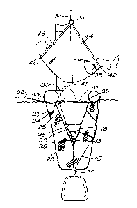
The apparatus of Figures 1 to 3 comprises a miniature
life raft or life buoy 1 having an irregular pentagon shape
defining a "bow" 2 and a "transom" 3. The buoy is given
its shape by a po~yether-coated, nylon woven textile inflatable
tube of circular cross-section when inflated and comprised
of five generally straight sections 4,5,6,7,8 angularly
joined together. In the simplest arrangemen-t, the tube is
arranged as a single compartment inflated from a pressurized
.. . . .
. ' ' ~ . .
' . .
~8~
gas bottle 9 on launch of the buoy. A pressure relief
valve - not shown - is provided. In use, it is over the
transom section 6 where a man overboard climbs, whilst the
bow sections 4,8 assist in supporting him semi-upright once
aboard. Accordingly the -transom section 6 has a smaller
diameter whilst the bow sec-tions 4,8 have a larger diameter.
The intervening sections 5,7 taper between the larger and
smaller diameters.
Connecting between the lowermost (in the normal floating
position) portions of the sections is a 100r 10 o~ the same
material as the tube. Below the Eloor is a connected
invert cone 11 of similar, though lightly coated fabric,
which forms a keel. It is provided with water ingress
apertures 12 at its tip and is otherwise closed, in particular
at its widest, upper part by being connected to ~he floor by
welding, except that three small breather holes 13 are
provided at the tip for drainage of water from the cone on
retrieval of the buoy. Below the tip hangs a mass 1~
having a fixed length or telescopic rigid rod 15 inter-
connecting the cone tip and the mass. The rod is rigid toensure that on launch the mass remains outside the buoy and
ultimately falls to its suspended position.
The purpose of the mass is to extend the cone on
launch. This causes the water to enter the cone through
the apertures 12. ~hese have inside, non-return valve,
.
- : . ,
., ~
- : , - ~ :
--8--
flaps 16 which act to pre~ent water egress as might o-ther-
wise occur if wind or waves were to lift the buoy above its
normally floating height. The arrangement thus opera-tes as
a semi-rigid keel. (Water egress through the breather
holes 13 is mlnimal during the huoyls movement in ridlncJ
waves.)
To assist a man overboard in climbing onto the life
buoy it is provided with a ladder hanging from the transon
section 6. The vertical parts 17 of the ladder are of
rope. The two rungs 18 are rigid. A pair of lines 17'
connect the lower rung to the mass 14 to ensure that the
rungs are pulled down on launch. To brace the rungs
against being swung away from a man trying to climb them,
their mid points are rigidly connected to points 19 on the
cone by rods 20. Handles 21 are provided on the sections
5,7.
The man's weight on the ladder will tend to lift the
bow 2. To counteract this a water pocket 22 which is
triangular in cross-section is secured to the underside of
the floox at the bow. It has water ingress apertures
towards the top of its sidewalls 23, fore and aft ones of
which are closed together laterally of the buoy. Chain
ballast 24 causes the pocket 22 to deploy for filling with
water. When the man climbs the ladder, water in the pocket
is lifted above the ambient water level and its weight tends
1~5B~8
g
to counterbalance the weight of the man.
The buoy is provided wi-th a drogue or sea anchor skirt 25
of open knitted nylon ma-terial. The skirt is in the ~orm
of a tube shackled to points 26 around the buoy and hanging
down therefrom. The bo-ttom of the skirt is gathered to a
lightly weighted ring 27. A downwards extending opening in
the skirt is provided at the steps 18 and the edges of the
opening are attached to the ropes 17, whereby the skirt does
not impede the ladder. The purpose of the drogue skirt is
to assist the keel in preventing the buoy from being blown
away from the man overboard before he can board it.` The
drogue skirt has a small cut out 25' at the bow to clear the
wa-ter pocket 22 and the rope 33 (described below).
As described the cone is circular in horizontal cross-
section and supported in this shape by upper and lower rigidrings 28,29 secured inside the cone. Other configurations
are envisaged to be possible.
The buoy is provided with a detachable sling 30 having
a lifting eye 31 from which extend three webbing supports
40,41,42 to pass across the man's back at his shoulder
blades, under his back side and behind his knees during
lifting as shown in Figure 3. Between the webbing supports
woven textile panels 43,44 are provided. VE~C~O (~egistered
trade mark) fastening strips 38, which normally retain the
sling in position in the buoy, are provided on the sling and
.
. : , ' .
~5~ 8
--10--
on the inflatable tube in positions shown in Figure 3.
In use, the life buoy 1 is launched,from a rigid cover
36. This is shown in Figures 4 and 5 and has two moulded
plast.ics material par-ts 237,238. The outer one 237 of -these
has a stepped lip 239 which accommodates the lip 240 o the
other 238. A stainless steel bracket 241 support~ the cover
prior to use of the apparatus on a yacht's "pushpit" rails
242,243. The bracket 241 has a generally L-shaped plate, the
. foot 245 of which carries the weight of the cover and engages
the lip 23~ at it~ lowest portion. The upright portion 246
of the plate carri.es a downwardly open hook 247 which engages
over the lower rail 242. Towards its top edge 248, the
portion 246 carries two welded-bnj upright tubes 2~9 in which
are accommodated the arms of an invert U rod 250. The U rod
carries an upwardly open hook 251 which engages under the
upper rail 243. The hooks 247,251 are held apart for gripping
the rails 242,243 by screw knobs 252 threadedly engaging the
arms of the U rod 250 through the tubes 249.
The cover 36 is held back against the upright portion
246 of the L plate 244 by a strap 253 passing through a slot in
the inner cover .part 238 and secured to a bar 254 provided
inside the outer cover part 237. The strap 253 has a buckle
fitt.ing 255 in which a tongue 256 of a release catch 257
engages. The tongue 257 projects in from a centrally
pivoted catch lever 258~ a spring biassing the tongue to
- : '. ,. .: , . '
.
, . -, -,, : ,. .
.
~L~8~
remain engaged. For launch of the life buoy, the tongue 257
is withdrawn by a second lever 259 bearing on the end of the
lever 258 opposlte from the tongue. The second lever is
also spring biassed and centrally pivoted. It has a .
release pull ring 2~0 secured to its end opposite ~rom the
lever 258. Thus pulling of the ring 260 away from the cover
36 moves the tongue 257 away and releases the buckle fitting
255.
A gas release cord 261 passes out of an opening in the
inner cover part 238 and is secured to the lower rail 242.
On launch of the apparatus, the entire cover 36 falls away
from the bracket 241 and hence its weight on the cord 261
withdraws a release pin (not shown) from the gas bottle 9.
The cover is opened by initial expansion of gas into the
tube 4,5,6,7,8. The packing of the buoy into the cover 36
is such that the mass 14 falls free at an early stage and
causes the invert cone keel 11 to deploy. The parts 237,238
of the cover remain attached together and come to hang via a
line 262 below the mass 14. The keel 11 is packed with
negligible air within it and consequently fills substantially
entirely with water. Thus the steps 18 are deployed below
the "stern" tube 6.
The man overboard swims to the buoy and clambers aboard
it, lies with his feet over the "stern" tube 6 and his head
and shoulders supported on the "bow" tubes 4,8. The sling
.
': '
58;~
-12-
30 extends beneath him. For visibility the buoy has a
self-erec-ting mas-t and flag 37.
Once the man is on -the buoy i-t cont.inues to drift only
slowly due to the action of -the drogue skirt and in due
course the vessel returns. It attaches a line 32 to ~ rope
33 hanging between two points 26 at the bows and a further
line 34 to the sling's lifting eye 31. The latter is
detachably mounted on the tube section 4 and on hoisting on
the line 34, the sling is pulled around the man who can be
thus swung aboard the vessel.
When he is thus safely rescued, the line 34 is connected
to a ring 35 on the floor 10 for lifting of the buoy from
the water. ~lthough the relatively small water pocket 22
remains full, the larger cone 11 drains slowly from the
breather holes 13. To relieve -the cone of the weight of
the mass 14 on lifting, a line 39 is provided between the
eye 35 and the upper end of the rod 15.
Second Embodiment
Referring to Figures 6 to 10, the life buoy 101 is
manufactured from a strong, waterprooE and airtight fabric~
The basic shape is of a tubular inflated ring formed into an
overall egg shape, one end being narrower than the other.
The actual size of the buoy is determined by the minimum
size required to support -the intrinsic weight, plus a man in
-
.
28S8;~8
--13--
wet clothing, but could be larger for use, say, on ships.
For safety the inflatable is divided into -three or more
buoyancy tanks 109 r see Figure 7, each with their own non-
return air valves. The 100r 110 o-f the buoy is a rigid
section of the same shape as the inflatable ring 101.
Incorporated in -this floor is a chamber for the gas canister
111 and the Eirst section of a rigid sea anchor leg 112.
Also incorporated is a hollow floor section 113 that houses
the inflation tubes from the gas canister to each of the
inflatable sections. VELCR0 tape 114 is attached to
several places inside the buoy, these correspond to tape
attached to the survival bag 115 described later. At the
narrower or bow end of the buoy ~the head end) is attached
on the outside a rubber type housing 116 into which the
audio-visual aid pole 117 is firmly inserted. At the wider
part ~the feet end3 are attached handles 118 which aid a man
to climb into the buoy using the steps 119 that are in-
corporated in the water pockets 221 described later. All
around the buoy are hand holds.
The inflatable ring folds onto and around the rigid
floor, and is inflated automatically when the rip-cord
attached to the gas canister is pulled.
For use, the buoy is packed into a rigid casing 100
divided into two parts, see Figure 9. The inner part is
attached securely to a vertical bracket hinged at the base
- , . ', ~..... : -
~35~
which in turn is attached securely to the side of the boa-t
(the most ef~ective position is likely to be over -the
transom). The hinged bracket is spring loaded and is kept
vertical by a fixed pole 102, see Figures 9 and 10. The
fixed pole incorpora-tes a handle release mechanism lQ3 and
use o~ this will resul-t in the launching o~ the buoy. Thc
outer casing is held in place by two catches, one at either
side and these are activated by turning a handle 104. This
handle is automatically turned by a sliding arm as the
bracket falls away from the vertical position. The handle
has an extension bar 105 protruding from one side of it.
There are two opposite grooves in the moving bracket 106
into which is fitted a sliding cross-bar which is integral
to an arm, bent in -the middle to avoid fouling the casing,
and which is hinged at the bottom 107. The hinge on this
arm is sited in front of the main bracket hinge so that when
the bracket moves downwards the cross-bar is pushed up the
groove and comes into contact with the extension bar 105 on
the handle; the handle is turned by this action
By the time the bracket and casing is approaching the
horizontal position the two catches have fully opened and
the outer casing, being ballasted, ~alls away into the water
taking with it the inflatable buoy. The rip-cord for
activating the gas canister(s), which in turn inflate the
buoy, is attached to the inner casing which stays with the
. , , : ~
'-
.
.
.
~L~85~
-15-
boat and is therefore pulled as the buoy falls away. The
inner casing can be removed from the bracke-t whilst in an
upright posi-tion by releasing a catch ancl lif-ting it o~f.
The bracket and casing have an interlocking wedge shape to
hold them together.
The life buoy 101 has a Eour sec-tion keel/sea anchor
structure: a rigid inner spine or telescopic leg, ballast,
a cloth sea anchor that is designed to offer the maximum
resistance in water when in the 'open' position, and a
series of water pockets that hang beneath the inflatable
buoy. The pockets incorporate steps on one side to aid a
person climhing into the buoy.
The purpose of the water pockets is to keep the buoy
sitting in the water. ~s wave action exposes one side of
the buoy the wind cannot easily get underneath and lift it
out because the outer skirt acts as a wall. Also as it is
lifted, the water in the pockets is raised above sea level
at that point and, water being heavier than air, it is
pulled back downwards keeping the buoy stable and firmly in
the water.
The telescopic leg is made up of several tubes of equal
length that slide and fit into one another. The top tube
112 is rigidly attached, or indeed can be integral to, the
floor 110. The other tubes 121, each diminishiny in
diameter form the telescopic leg. The bottom tube is
.~
~ -: ,. - : '' ' :
~285~
rigidly attached to the ballasted casing 100. To reduce
friction each tube is in fact a loose Ei-t wi-thin -the other
but lips 122, integral to each tube, one at the top on the
outside and one at the bo-ttom in -the inside, form a sliding
fit between each successive tube and also act as a stop when
each tube is fully extended. To reduce Eriction even
further each lip is grooved longitudinally around lts
sliding face, see Figure 2, cross-section A-A. The third
tube down is blanked-off at the top 123. An inflatable
'piston' 124 is inflated along with the buoyancy tanks and
forces down the first three sections of the telescopic leg
by pushing against the plate 123 on top of tube number 103.
With the extension of the first three tubes, the ballast is
also exten~ed and the buoy is therefore sel~ righting and
will always float the correct way up. The tube 112 is
longer than the other tubes in that it enters into the floor
11~ box section to allow enough room at the top for the
inflatable piston 1?~4 to be stowed when the telescopic arms
are in the closed position.
Ballast is actually integral to the outer casing 101
into which a-t least half of the buoy is encased when stowed.
The bottom leg of the telescopic arm is securely attached to
the inside of the casing. The casing is made oE non
corrosive material and has fixing points around the inside
for attaching a cloth sea anchor.
-:
.
-: ' ' . , : ' '
-
~358~
-17-
The cloth sea ancho~ 125 is made up o~ several sheets
of suitable cloth (waxed canvas, nylon or plasticised
material) that should weather well in sea water. Each
sheet is an identical shape, see Figure 8. The outline
shape is that o~ the plan shape oE ~he buoy, (wider a~ one
end than the other and rounded). The si~e of each sheet is
the same as, or sligh-tly larger than, the buoy floor (this
simply avoids problems in packing). The centre of each
sheet is cut out in the same shape as the outside edge.
This is to house the central telescopic leg 112,121 and also
the smaller diameter canister holder 111.
The sheets of cloth are strongly stitched together in
the following way. If six sheets are used, they are
divided into three pairs, Each oE the pairs are stitched
together along radial lines 126. The top and bottom sheets
o~ each pair are s itched together along the short lines
127. Cloth straps are stitched to the top and bottom
sheets ln the same place 127. These straps are attached to
the anchor ring 128 at the top and the ballasted casing at
the bottom. ~7hen the cloth anchor is folded the pieces lie
flat, one on top of the other. When it is opened, or
extended, the stitching pattern causes a pocketed concertina
that ofers considerable resistance to movement when immersed
in water.
The water pockets 221 are made of watertight material.
: - : . . ,
.
'
~X858~
-18-
They are securely attached -to the inflatable section 109 and
hang all round the buoy. There is an inner 129 and an
outer 130 skirt and a cloth floor tha-t takes the plan shape
of the inflated buoy. At intexvals around the pockets are
stitched weighted hars 131 in a radial fashion. These help
to open the pockets aEter the buoy has inflated and riyhted
itself in the water. ~lso in a radial fashion are stitched
several inside walls between the inner and outer skirt.
Several pockets are therefore formed which prevent water
flowing freely around the 'sack'.
Water enters the pockets through holes reinforced with
rigid rings 132 situated at the top of each pocket. The
bottom of the pockets are held in shape by a weighted ring
128 which takes the shape o~, and is just larger than the
buoy floor. The ring is fastened to the inner skirt.
At the wider end of the buoy (the feet end) are incorporated
steps 119 to help a person climb into the buoy. The upper
two steps are incorporated in ~he outer skirt of the water
pockets, the third (and subsequent steps if required) is
suspended from a rope at either side and attached to the
ends of the second step. ~11 the steps have some weight
and do not float, so that they maintain their position.
The water pocket behind the steps is narrower because the
outer skirt is nearer to the inner one to allow enough space
for a person to easily locate them and also to provide a
.
.
: , . . -: - -
. . . : ,
.. , . ~ . . .
~s~
--19--
space for his feet when climbing in.
Third ~mbodiment
The emhodimen-t oE Figures 11 and 12 is similar to that
of Figures 6 to 10 exGept tha-t instead Oe a telescopic leg
this embodimen-t uses hingecl arms 133. Each arm is hinged
at the ends. The top arm and the bottom arm are half the
length of the middle arms so that when they fold up against
and alongside each other they stretch from one side of the
rigid buoy floor 110 to the other without overhanging. The
top and bottom arms are attached -to the middle of the buoy
floor 110 and the ballasted casing lQ0 respectively, though
these can be repositioned to coincide with the centre of
balance if this is not in the middle. The hinges incorpo-
rate a ratchet device that pre~ents the axm from foldingback on itself as it extends downwards. When fully extended
the arms become vertical, and with the ratchet system, form
a rigid leg between -the flGating buoy and the submerged
ballast. The number o~ arms employed depends upon how deep
you wish the sea anchor to go.
The gas canister casing 111 is repositioned horiæon-
tally under the buoy floor 110 and alongside and parallel to
the hinged arms. This allows the floor to be packed closer
to the bottom of the ballasted casing 100.
The cloth sea anchor is made of the same type of fabric
.
- - . .
', . ~ .
~L285~3~8
-20-
as described for the telescopic leg method earlier, but the
shape of the cent~e hole needs to be modified to give a
clear passage to -the hinged a.rms that re~uire a slot ra-ther
than a hole. The cloth sea anchor takes the same outer
shape as previously described and .is oE the same outer
dimensions. ~gain there are several sheets cut to the same
shape. ~ slot 134 is cut out o -the sheets up the centre
lengthways, the slot being wide enough to house the folded
legs. At each end of the slot are attached straps 135
10 which hold the two halves together. The sheets are stitched :
together in exactly the same way as previously described,
except there are short stitches 127 to be made on the
inside. These are to join the same pieces of cloth as do
the outer ones 127.
The number of sheets usea to make the sea anchor
depends upon how deep the whole unit is required to go and
how many arms are used to make up the rigid length. There
will be an optimum size for the sea anchor in relation to
the size of the inflated buoy.
Both the second and third embodiments have a sling/
survival hag, having two purposes. Firstly it is to wrap
around the man in the buoy to protect him from the weather,
and secondly to form a hammock like sling with one large
lifting eye at its apex, so that when the unit is lifted it
forms a secure bag so that a man in it cannot fall out.
,
~8~8~3
-21-
To achieve -this there are -two par~s to the 'bag'.
The first ~art forms the lifting sling, see Figu~e 6.
It is made of strong nylon Eabric and is reinforced at its
outer edges and in the middle with strong webbing that
converge upon the strong ri~id lifting eye at the apex.
When lifted the sling Eorms a hammock shape that is lower in
the middle and higher at the ends. The ends lift a ~an's
legs and head higher than his torso, which remains in t'ne
'hollow' of the sling. In this position it is not possible
for him to fall out. At the bottom of the sling are Velcro
strips 114 that allow it he firmly secured to the buoy, the
bottom of the sling following the contours of the inside of
the buoy. The sides of the sling are laid lengthways along
the sides of the buoy with the lifting eye at the head end.
lS This is held in place by Velcro strips.
The man enters the buoy from the water at the feet end,
collapses into the buoy and rolls over to assume a half
sitting, half lying position within the contours of the
buoy, the walls of the inflatable giving support to the back
and legs. The lifting eye is at this stage in a prominent
position behind the man's head. When it is lifted the
Velcro strips along the edges give way and the sling assumes
the hammock shape. As the unit is lifted higher the whole
unit comes detached from the buoy, as shown in Figure 6.
The man is now lifted aboard safely and easily, leaving the
, ' ;' , '
. .: : -.
-
1~85~
~22-
weighted buoy in the water. After use the bag is slmply
put back in position usiny the Velcro strips. It is -then
folded with the de~lated buoy ready for use once more.
The second part of the bag deals with the protective
5 covering that shelters the man from the elemen-ts. In
effect it is a wrap-around bag oE suitable material~ and
forms the inner part of a bag within a bag. The base of
the inner bag is sewn into the outer sling and therefore its
base follows the same contours as the outer sling. The
inner bag is long enough to cover a large man and incorporates
in the head end an elasticated hood. The sides are loosely
held open for a man to climb in by Velcro tape. The man,
once in the buoy, wraps the sides around himself. ~gain
Velcro tape is used to keep the bag 'shut'.
~ocation devices 136 are situated on top of a short
mast 117 which is firmly held in a vertical position ~when
the buoy is inflated) by a rubber type holder on the outer
side of the inflatable section at the head end. The actual
siting of the mast is not critical, but must not be fouled
2~ by a man climbing int~ the craft.
The first location aid is a flashing strobe light which
will benefit both the vessel and the man in the water,
especially at night. The second device is an audible sound
emitter that could help a vessel in fog and also a man in
the water who loses sight of ~he buoy periodically due to
.
- . . : . -
' - - '
~ ~85~
-23-
choppy seas. The third aid is a radio bleep transmitter
that can be tracked using the hoat's radio direction findin~
equipment. These aids are brand items bought on the market
and lncorporated in the mas-t. ~lowever, they can be modified
to be powered from one common battery pack also incorpora-~ed
in the mast and all activa-ted by one ontoEf swit~h. '~'he
on/off switch can be activated by gravity as the mast
assumes its vertical position, or a small rip-cord method
can be used.
After the man has been brought aboard using the de-
tachable sling the buoy is brought aboard in a similar
fashion. Another large li~-ting eye lying in the bottom of
the buoy floor is exposed by the removal of the sling.
Each of three ropes attached to this passes through one of
three holes positioned at three equidistant points around
the edges of the buoy floor. They each enter -the top of
the water poc~ets via the inner water inlet holes, and
proceed down to the ring 128 used to hold the water pockets
relative to each other. Each rope is attached to this
ring. The ropes are taken down the inside of the water
pockets to avoid fouling the keel mechanism. When the buoy
lifting ring is raised using the same extended boom or
derrick used to lift the man aboard, the ring 128 is lifted
and this has the effect of reducing the size of the water
pockets whilst in the water and expelling water from them
:
.
.
~8S~3~8
-2~-
out of the same holes it previously en-tered.
Once the ring engages with the buoy floor the lifting
effort now acts on -the buoy itself. It is raised out of
-the water and laid on the deck. ~ecause the water pockets
have been emptied of a lot of their water the whole uni-t is
lighter than it would have been.
After use the keel section is olded irst into the
ballasted casing. The survival bag is repositioned before
the buoy is deflated. The buoy is now deflated using the
release valves. Using a 'repacking kit' the batteries and
gas canister are replaced and the release valves are re-
sealed. The launching bracket is brought back to its
vertical position and the inner casing removed. The buoy
is packed into both casings, the rip-cord attached and the
whole unit re-positioned on the launching bracket ready for
use once more.
:
: ' ' . ' , :
- . ' ~ . - ,. : ..
~. ' . ' ' .