Sélection de la langue

Search

Sommaire du brevet 1285829 

Énoncé de désistement de responsabilité concernant l'information provenant de tiers

Une partie des informations de ce site Web a été fournie par des sources externes. Le gouvernement du Canada n'assume aucune responsabilité concernant la précision, l'actualité ou la fiabilité des informations fournies par les sources externes. Les utilisateurs qui désirent employer cette information devraient consulter directement la source des informations. Le contenu fourni par les sources externes n'est pas assujetti aux exigences sur les langues officielles, la protection des renseignements personnels et l'accessibilité.

Disponibilité de l'Abrégé et des Revendications

L'apparition de différences dans le texte et l'image des Revendications et de l'Abrégé dépend du moment auquel le document est publié. Les textes des Revendications et de l'Abrégé sont affichés :

  • lorsque la demande peut être examinée par le public;
  • lorsque le brevet est émis (délivrance).
(12) Brevet: (11) CA 1285829
(21) Numéro de la demande: 1285829
(54) Titre français: MECANISME SELECTEUR D'ECHAPPEMENT POUR PROPULSEUR ARRIERE DE BATEAU
(54) Titre anglais: EXHAUST CONTROL ASSEMBLY FOR MARINE STERN DRIVE
Statut: Durée expirée - après l'octroi
Données bibliographiques
(51) Classification internationale des brevets (CIB):
  • B63H 21/32 (2006.01)
  • F01N 13/08 (2010.01)
  • F01N 13/12 (2010.01)
  • F02B 61/04 (2006.01)
(72) Inventeurs :
  • WINBERG, ARVID E. (Etats-Unis d'Amérique)
  • LITJENS, JOHN J. (Etats-Unis d'Amérique)
(73) Titulaires :
  • BRUNSWICK CORPORATION
(71) Demandeurs :
  • BRUNSWICK CORPORATION (Etats-Unis d'Amérique)
(74) Agent: RICHARD J. MITCHELLMITCHELL, RICHARD J.
(74) Co-agent:
(45) Délivré: 1991-07-09
(22) Date de dépôt: 1987-12-16
Licence disponible: S.O.
Cédé au domaine public: S.O.
(25) Langue des documents déposés: Anglais

Traité de coopération en matière de brevets (PCT): Non

(30) Données de priorité de la demande:
Numéro de la demande Pays / territoire Date
942,609 (Etats-Unis d'Amérique) 1986-12-17

Abrégés

Abrégé anglais


ABSTRACT
A stern drive marine propulsion system
nas an inboard engine with an exhaust , an
outboard drive unit operatively coupled to the
engine and separated therefrom by a transom
having two exhaust passages therethrough,
and an exhaust control assembly aft of the engine
exhaust and forward of the transom and within
the boat . The assembly has an inlet
connected to the engine exhaust , and has first and
second outlets communicating with the re-
spective exhaust passages extending aft
through the transom . A valve in the as-
sembly selectively controls communication of the
inlet with the first outlet .

Revendications

Note : Les revendications sont présentées dans la langue officielle dans laquelle elles ont été soumises.


- 6 -
The embodiments of the invention in which an
exclusive property or privilege is claimed are defined as
follows:
1. An exhaust control assembly for use in a stern
drive marine propulsion system having an inboard engine
with an exhaust and having an outboard drive unit and
propeller operatively coupled to said engine and separated
therefrom by a transom, an exhaust control assembly aft of
said engine exhaust and forward of said transom, said
assembly having an inlet connected to said engine exhaust,
and having first and second outlets, valve means in said
assembly for electively controlling communication of said
inlet with said first outlet, wherein said first outlet is
connected to first passage extending aft through said
transom, said second outlet is connected to a second
passage extending aft through said transom through said
outboard drive unit and discharging said propellor, said
valve means has a first position passage engine exhaust to
first and has a second position blocking passage of
passage engine exhaust to said first passage, and wherein
said second passage is always in communication with engine
exhaust at said inlet, regardless of the position of said
valve means, such that said propeller is always in
communication with exhaust.
2. The assembly of Claim 1 wherein said inlet
and said first outlet form a straight-through passage, and
wherein said second outlet extends from the interface of
said inlet and first outlet at an angle to said
straight-through passage to define a bent passage from
said inlet to said second outlet.
3. The assembly of claim 2 wherein said valve
means comprises a butterfly valve at the entrance to said
first outlet, said butterfly valve having a first open
position substantially parallel to said straight-through
passage and providing communication of said inlet with
said first outlet, said butterfly valve having a second
closed position substantially parallel to the passage
through said second outlet and providing the bend in said

- 7 -
bent passage and deflecting exhaust from said inlet to
said second outlet.
4. The assembly of Claim 1 wherein said valve
means comprises a plate-like disc mounted on a shaft
extending through the interior of said assembly and
pivotally mounted thereto, at least one end of said shaft
extending exteriorly of said assembly.
5. The assembly of Claim 4 comprising pneumatic
actuator means on the same side of said transom as said
assembly, and linkage means connected between said
exterior end of said shaft and said pneumatic actuator
means and responsive to the latter to pivot said shaft.
6. The assembly of claim 5 wherein said
pneumatic actuator means comprises an air cylinder mounted
to said assembly independently of said transom, such that
said assembly and said valve means and said air cylinder
are all forward of said transom, and such that the
condition of said valve means is calibrated according to
position and orientation of said air cylinder on said
assembly independently of position and orientation
relative to said transom.
7. A stern drive marine propulsion system for a
boat having a transom, comprising: an inboard engine with
an exhaust; an outboard drive unit operatively coupled to
said engine and separated therefrom by said transom; a
first aperture in said transom; a second aperture in said
transom; an exhaust control assembly aft of said engine
exhaust and forward of said transom, said assembly having
an inlet connected to said engine exhaust, and having
first and second outlets, and valve means in said assembly
for selectively controlling communication of said inlet
with said first outlet; first passage means connected to
said first outlet of said assembly and extending aft
through said first aperture in said transom; second
passage means connected to said second outlet of

- 8 -
said assembly and extending aft through said second
aperture in said transom to said outboard drive unit to
discharge said exhaust through said outboard drive unit at
said propellor wherein said valve means has first
condition passing engine exhaust to said first passage
means, and has a second condition blocking passage of
engine exhaust to said first passage means, and wherein
said second passage means is always in communication with
engine exhaust at said inlet, regardless of the condition
of said valve means, such that said propeller is always in
communication with engine exhaust.
8. The invention according to claim 7 wherein:
said inlet and said first outlet of said assembly and said
first passage through said first aperture in said transom
form a substantially straight-through passage; said second
outlet of said assembly extends from the interface of said
inlet and said first outlet of said assembly at an angle
to said straight-through passage to define a bent passage
from said inlet to said second outlet of said assembly.
9. The invention according to 8 wherein said
valve means comprises: a plate-like disc mounted on a
shaft extending through the interior of said assembly and
pivotally mounted thereto, at least one end of said shaft
extending exteriorly of said assembly; an air cylinder
mounted to said assembly and including an extensible and
retractable piston; linkage means connected to said
exterior end of said shaft and said piston to pivot said
shaft in response to extension and retraction of said
piston to operate said valve means between said first and
second conditions.
10. A stern drive marine propulsion system for a
boat having a transom, comprising: an inboard engine with
an exhaust; an outboard drive unit operatively coupled to
said engine and separated therefrom by said transom; an
exhaust control assembly aft of said engine exhaust and
forward of said transom, said assembly having an inlet

- 9 -
connected to said engine exhaust, and having first and
second outlets, and a valve in said assembly having a
first condition providing communication of said inlet with
said first outlet, and a second condition blocking
communication of said inlet with said first outlet and
first passage means connected to said first outlet and
extending aft through said transom; second passage means
connected to said first outlet engine extending aft
through said tramson; control circuitry for said valve
comprising: an air cylinder operatively coupled to said
valve for selectively controlling actuation of said valve
between said first and second conditions; an air pump for
supplying pressurized air to said air cylinder; a
regulator valve for regulating the pressure supplied by
said air pump to said air cylinder; a check valve between
said air pump and said air cylinder back-pressure from
said air cylinder to said air pump; a relief valve for
affirmatively depressurizing said air cylinder and
changing the valve condition a source of electrical power;
electric switch means for selectively completing an
electric circuit from said source of electrical power to
said air pump to actuate the latter to supply said
pressurized air to said air cylinder, and for selectively
completing an electric circuit from said source of
electrical power to said relief valve to actuate the
latter to depressurize said air cylinder.

Description

Note : Les descriptions sont présentées dans la langue officielle dans laquelle elles ont été soumises.

~ ~?,858~
The invention relates to an exhaust system for a
stern drive marine propulsion system.
The present invention generally provides an
exhaust control assembly for use in a stern drive marine
propulsion system having an inboard engine with an exhaust
and having an outborad drive unit operatively coupled to
said engine and separated therefrom by a transom and
wherein said assembly is adapted to be disposed a~t of
said engine exhaust and forward of said transom, said
assembly including an inlet connected to said engine
exhaust, and having first and second outlets, said
assembly also having valve means for selectively
controlling communication of said inlet with said first
outlet.
The present invention further provides an exhaust
control assembly for use in a stern drive marine
propulsion system having an inboard engine with an exhaust
and having an outboard drive unit and propeller
operatively coupled to said engine and separated therefrom
by a transom, an exhaust control assembly aft o said
engine exhaust and forward of said transom, said assembly
having an inlet connected to said engine exhaust, and
having first and second outlets, valve means in said
assembly for selectively controlling communication of said
inlet with said first outlet, wherein said first outlet is
connected to first passage extending aft through said
transom, said second outlet is connected to a second
passage extending aft through said transom through said
outboard drive unit and discharging said propellor, said
valve means has a first position passage engine exhaust to
first and has a second position blocking passage of
passage engine exhaust to said first passage, and wherein
~ ' ~ V ' ~
;~- ,"
- .
. . -
- : .- , -- -
~ . . ..
,, . ' . ~ ~ .
. .

~2~ 29
-- 2
said second passage is always in communication with engine
exhaust at said inlet, regardless o~ the position of said
valve means, such that said propeller is always in
communication with exhaust.
The system of the invention enables less
stringent mounting and int~grity requirements, and also
enables accurate precalibration o~ the valve means
independently of position and orientation relative to the
transom.
Further features and advantages of the invention
will become more apparent from the followlng description
o~ a preferred embodiment taken together with the
accompanying drawings wherein:
Fig. 1 is a view of a stern drive marine
propulsion system with an exhaust assembly in accardance
with the invention;
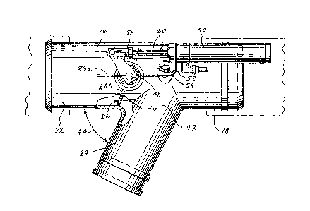
Fig. 2 is a side elevation view of the exhaust
assembly of Fig. l;
Fig. 3 is an end view of the assembly of Fig. 2;
Fig. 4 is a top view of the assembly oP Fig. 2;
and
Fig. 5 is a schematic circuit diagram of the
control circuitry for the valve in the exhaust assembly of
Fig. 1.
Fig. 1 shows a stern drive marine propulsion ~ -
system 2 having an inboard engine 4 with an exhaust at
exhaust elbow 6, and having an outboard drive unit 8
operatively coupled to the engine and separated therefrom
by transom 10 of boat 12. Engine 4 is drivingly connected
to propeller 14 for propelling boat 12. Exhaust elbow 6
is shown and described more fully in U.S. Patent No.
4,573,318.
Exhaust control assembly 16 is aft of engine
exhaust elbow 6 and forward of transom 10. Assembly 16
has an inlet 18 connected to exhaust elbow 6 by a tubular
rubber or the like sleeve 20 fitting snugly
'
. ' ' ~, ' ' ' .',, ' . ' . ' .
- . . ~' ', ' :'
- "'
. .
~. '.,' ~ '

35~2~
-- 3 --
around inlet 18 and the outlet of eY~haust elbow 6.
Assembly 16 has first and second outlets 22 and 24. ;i
Valve 26 selectively controls communication of inlet
18 with outlet 22. Outlet 22 is connected to exhaust
5 passage pipe 28 extending aft through a first aper~ure
30 in transom 10. Outlet 22 is connected to pipe 28 by
tubular rubber or the like sleeve 32 fitting snugly
therearound. Outlet 2~ is connected to exhaust pas~
sage pipe 34 extending aft through a second aperture
10 36 in transom 10 as shown in U.S. Patent No. 4,178,
873. As an alternative to slip joint 37, a bellows
connection may be used. The exhaust passage through
pipe 34 extends through outboard drive unit 8 and pro-
peller 14 as shown at discharge passage 38. Outlet 24
15 is connected to exhaust passage pipe 34 by tubular
rubber or the like sleeve 40 fitting snugly therearound.
Valve 26 is in outlet 22 and has a first
condition as shown at 26a, Fig. 2, providing communica-
tion of inlet 18 with outlet 22, and has a second con-
20 dition as shown at 26b blocking communication of inlet18 with outlet 22. Inlet 18 and outlet 22 form a
straight-through passage. Outlet 24 extends from the
interface 42 of inlet 18 and outlet 22 at an angle 44
to the straight-through passage, to define a bent pas-
25 sage from inlet 18 to outlet 24. Valve 26 is a butter-
fly valve at the entrance to outlet 22, and is provided
by a plate-like disc 46 mounted on a shaft 48 extending
through the interior of the assembly and pivotally
mounted to the sidewalls thereof. In the first open
30 position 26a, disk 46 of the butterfly valve is paral-
lel to the straight-through passage and provides com-
munication of inlet 18 with outlet 22. In the second
closed position 26b, disk 46 of the butterfly valve is
su~stantiaily_ parallel to the passage through outlet
35 24 and provides the bend in the bent passage and de-
flects exhaust from inlet 18 to outlet 24. Water-
proof and exhaust-proof gaskets (not shown) are pro-
vided between the shaft and the sidewalls of the

~285~2~
-- 4
assembly to seal the shaft and prevent leakage there-
past.
A pneumatic actuator is provided by an air
cylinder 50 mo~lnted by bracket 52 and bolts 54 to
5 assembly 16, and is on the same side of transom 10
as assembly 16. End 56, Figs. 3 and 4, o~ shaft 48
extends exteriorly of assembly 16 and is connec-ted by
linkage 58 to extensible and retractable piston 60 of
air cylinder 50, such that linkage 58 pivots shaft 48
10 in response to extension and retraction of piston 60
to operate valve 26 between open condition 26a and
closed condition 26b.
Air cylinder 50 is mounted to assembly 16
independently of transom 10. Assembly 16, valve 26
15 ~nd air cylinder 50 are all forward of transom 10.
rhe condition of valve 26 is calibrated according to
position and orientation of air cylinder 50 on assembly
16 independently of position and orientation relative
to transom 10.
Fig. 5 shows control circuitry for valve 26.
Air cylinder 50 is a Parker fluid power Part No.
1.06RSRY02.0EV. Air cylinder 50 is internally spring
biased such that piston 60 is normally e~tended, and
hence butterfly valve 26 is normally in the closed
25 position 26b. An air pump 62 is provided for supplying
pressurized air to air cylinder 50. Air pump 62 is
a Thomas Industries compressor Part No. 405ADC38/12.
A regulator valve 64 is provided for regulating the
pressure supplied by air pump 62 to air cylinder 50,
30 to prevent overpressuring and damaging the system.
l~egulator valve 64 is a Circle Seal Controls relief ~;
valve Part No. 532IM30. A one-way check valve 66 is ~,
provided between air pump 62 and air cylinder 50
blocking back-pressure from air cylinder 50 to air pump
35 62, to prevent the system from leaking and changing the
valve position. Check valve 66 is a Circle Seal
- .' : - ' ~ ~ '
, - . .' ' : ' ,' ., ' '
.
.

11 Z~358~9
-- 5
Controls check valve Part No. 2232B-I~. A relief
valve 68 is provided for affirmatively depressurizing
the air cylinder and changing valve position. Relief
valve 68 is a Skinner Electric Solenoid Valve ~atalog
No. B2DA1175. A source of electrical power is provided
by the boat battery 70. An electric swltch 72 is
provided for selectively completing an electric circuit
from battery 70 to air pump 62 to actuate the latter
to supply pressurized air to air cylinder 50, and for
10 selectively completing an electric circuit from battery
70 to solenoid relief valve 68 to actuate the latter
to depressurize air cylinder 50. Switch 72 is a Cutler
Hammer switch Part No. 8946K691. Switch 72 is in-
ternally spring loaded to the center neutral position,
15 wherein both the circuit to air pump 62 and to valve
68 are open. Switch 72 is actuated in one direction
to close the circuit to air pump 62, and is actuated in
the other direction to close the circuit to valve 68.
The system is conveniently operated by the boat op-
20 erator from the driving position.
The type of system in which the present in~vention is typically used is shown in U.S. Patent No.
4,504,238.
It is recognized that various equivalents,
25 alternatives, ~d modifications are possible within
the scope of the appended claims.
. . .
. ~ , : . ' .
~ ' ~' . ,,, -

Dessin représentatif
Une figure unique qui représente un dessin illustrant l'invention.
États administratifs

2024-08-01 : Dans le cadre de la transition vers les Brevets de nouvelle génération (BNG), la base de données sur les brevets canadiens (BDBC) contient désormais un Historique d'événement plus détaillé, qui reproduit le Journal des événements de notre nouvelle solution interne.

Veuillez noter que les événements débutant par « Inactive : » se réfèrent à des événements qui ne sont plus utilisés dans notre nouvelle solution interne.

Pour une meilleure compréhension de l'état de la demande ou brevet qui figure sur cette page, la rubrique Mise en garde , et les descriptions de Brevet , Historique d'événement , Taxes périodiques et Historique des paiements devraient être consultées.

Historique d'événement

Description Date
Inactive : CIB désactivée 2011-07-26
Inactive : CIB de MCD 2010-02-01
Inactive : CIB expirée 2010-01-01
Inactive : Périmé (brevet sous l'ancienne loi) date de péremption possible la plus tardive 2008-07-09
Inactive : CIB de MCD 2006-03-11
Accordé par délivrance 1991-07-09

Historique d'abandonnement

Il n'y a pas d'historique d'abandonnement

Titulaires au dossier

Les titulaires actuels et antérieures au dossier sont affichés en ordre alphabétique.

Titulaires actuels au dossier
BRUNSWICK CORPORATION
Titulaires antérieures au dossier
ARVID E. WINBERG
JOHN J. LITJENS
Les propriétaires antérieurs qui ne figurent pas dans la liste des « Propriétaires au dossier » apparaîtront dans d'autres documents au dossier.
Documents

Pour visionner les fichiers sélectionnés, entrer le code reCAPTCHA :


Pour visualiser une image, cliquer sur un lien dans la colonne description du document. Pour télécharger l'image (les images), cliquer l'une ou plusieurs cases à cocher dans la première colonne et ensuite cliquer sur le bouton "Télécharger sélection en format PDF (archive Zip)" ou le bouton "Télécharger sélection (en un fichier PDF fusionné)".

Liste des documents de brevet publiés et non publiés sur la BDBC .

Si vous avez des difficultés à accéder au contenu, veuillez communiquer avec le Centre de services à la clientèle au 1-866-997-1936, ou envoyer un courriel au Centre de service à la clientèle de l'OPIC.


Description du
Document 
Date
(aaaa-mm-jj) 
Nombre de pages   Taille de l'image (Ko) 
Revendications 1993-10-21 4 186
Page couverture 1993-10-21 1 15
Dessins 1993-10-21 2 79
Abrégé 1993-10-21 1 18
Description 1993-10-21 5 209
Dessin représentatif 2001-11-14 1 18
Taxes 1996-06-20 1 63
Taxes 1994-06-17 1 68
Taxes 1995-06-21 1 61
Taxes 1993-06-21 1 52