Sélection de la langue

Search

Sommaire du brevet 1286017 

Énoncé de désistement de responsabilité concernant l'information provenant de tiers

Une partie des informations de ce site Web a été fournie par des sources externes. Le gouvernement du Canada n'assume aucune responsabilité concernant la précision, l'actualité ou la fiabilité des informations fournies par les sources externes. Les utilisateurs qui désirent employer cette information devraient consulter directement la source des informations. Le contenu fourni par les sources externes n'est pas assujetti aux exigences sur les langues officielles, la protection des renseignements personnels et l'accessibilité.

Disponibilité de l'Abrégé et des Revendications

L'apparition de différences dans le texte et l'image des Revendications et de l'Abrégé dépend du moment auquel le document est publié. Les textes des Revendications et de l'Abrégé sont affichés :

  • lorsque la demande peut être examinée par le public;
  • lorsque le brevet est émis (délivrance).
(12) Brevet: (11) CA 1286017
(21) Numéro de la demande: 1286017
(54) Titre français: DISPOSITIF DE GARDIENNAGE DES YEUX D'UN CONDUCTEUR
(54) Titre anglais: APPARATUS FOR MONITORING THE EYES OF AN OPERATOR
Statut: Périmé et au-delà du délai pour l’annulation
Données bibliographiques
(51) Classification internationale des brevets (CIB):
  • A61B 3/10 (2006.01)
  • A61B 3/113 (2006.01)
  • A61B 5/11 (2006.01)
(72) Inventeurs :
  • MORAN, DAN (Israël)
  • GERLITZ, YONATAN (Israël)
(73) Titulaires :
  • RASAAT
(71) Demandeurs :
  • RASAAT (Israël)
(74) Agent: SMART & BIGGAR LP
(74) Co-agent:
(45) Délivré: 1991-07-09
(22) Date de dépôt: 1988-03-09
Licence disponible: S.O.
Cédé au domaine public: S.O.
(25) Langue des documents déposés: Anglais

Traité de coopération en matière de brevets (PCT): Non

(30) Données de priorité de la demande:
Numéro de la demande Pays / territoire Date
81928 (Israël) 1987-03-18

Abrégés

Abrégé anglais


ABSTRACT
Apparatus for monitoring the eye of a subject
comprising: apparatus for directing infra-red radiation at the
eyes of a subject; apparatus for sensing infra-red radiation
retro-reflected by the retina through the cornea of the subject;
and apparatus for providing a sensible output indication in the
absence of expected received retroreflected radiation, indicating
the closing of the subject's eyes or direction of his eyes
outside of a desired angular region.

Revendications

Note : Les revendications sont présentées dans la langue officielle dans laquelle elles ont été soumises.


THE EMBODIMENTS OF THE INVENTION IN WHICH AN EXCLUSIVE
PROPERTY OR PRIVILEGE IS CLAIMED ARE DEFINED AS FOLLOWS:
1. Apparatus for monitoring the eye of a subject
comprising:
means for directing radiation at the eyes of a subject;
means for sensing radiation retroreflected by the
retina through the cornea of an eye of the subject;
scanning means for causing said means for directing and
said means for sensing to scan a given angular region in at least
one direction; and
means for providing a sensible output indication in the
absence of expected received retroreflected radiation.
2. Apparatus according to claim 1 and wherein said
radiation is outside the visible spectrum.
3. Apparatus according to claim 1 and wherein said
radiation is infrared radiation.
4. Apparatus according to claim 2 and wherein said
radiation is infrared radiation.
5. Apparatus according to claim 1 and wherein said
scanning means are operative to scan in two orthogonal
directions.
6. Apparatus according to claim 2 and wherein said
scanning means are operative to scan in two orthogonal
directions.

7. Apparatus according to claim 1 and wherein said
scanning means are operative to scan in a horizontal plane.
8. Apparatus according to claim 2 and wherein said
scanning means are operative to scan in a horizontal plane.
Apparatus according to claim 1 and wherein said means
for directing comprise a collimating lens.
10. Apparatus according to claim 2 and wherein said means
for directing comprise a collimating lens.
11. Apparatus according to claim 3 and wherein said means
for directing comprise a collimating lens.
12. Apparatus according to claim 4 and wherein said means
for directing comprise a collimating lens.
13. Apparatus according to claim 5 and wherein said means
for directing comprise a collimating lens.
14. Apparatus according to claim 1 and wherein said means
for sensing comprise a beam splitter and an infra-red detector.
15. Apparatus according to claim 2 and wherein said means
for sensing comprise a beam splitter and an infra-red detector.
16. Apparatus according to claim 1 and wherein said means

for providing include circuitry receiving inputs representing the
timing of radiation outputs from said means for directing and
inputs representing the timing of retroreflected radiation
received by said means for sensing, for providing an alarm
actuation output signal.
17. Apparatus according to claim 2 and wherein said means
for providing include circuitry receiving inputs representing the
timing of radiation outputs from said means for directing and
inputs representing the timing of retroreflected radiation
received by said means for sensing, for providing an alarm
actuation output signal.
18. Apparatus according to claim 1 and wherein said means
for providing an sensible output indication in the absence of
expected received retroreflected radiation is operative for
indicating the closing of the operator's eyes or direction of his
eyes outside of a desired angular region.
19. Apparatus according to claim 2 and wherein said means
for providing an sensible output indication in the absence of
expected received retroreflected radiation is operative for
indicating the closing of the operator's eyes or direction of his
eyes outside of a desired angular region.

Description

Note : Les descriptions sont présentées dans la langue officielle dans laquelle elles ont été soumises.

FIELD OF THE INVENTION
The present invention relates to electro-optical
alertness monitoring apparatus and more par~icularly to apparatus
for monitoring the eyes of an operator.
BACKGROUND OF THE INVENTION
~ arious types of apparatus have been proposed for
maintaining alertness of drivers and operators of machinery. U.S.
Patents ~,724,1~9 and 3,863,262 to Skolnick et al describe a
sleep inhibitor for automobile drivers wherein light from a lamp
is reflected from the driver's eyeball in order to activate an
alarm when the eyeball is covered by the eyelid for more than a
predetermined time. U.S. Patent 3,379,885 to Nork describes a
sight switch employing an infrared source and sensor which
distinguishes between reflections from the white of the eyeball
and the iris. Two other U.S. patents, nos. 4,397,531 and
4, fi25, 337, use relatively expensive two dimensional image
scanners and very heavy software to analyze the image.
`~' .`
.

SUMMARY OF THE INVENTION
The present invention seeks to provide improved
apparatus for monitoring operator alertness. There is thus
provided in accordance with a preferred embodiment of the present
invention apparatus for monitoring the eye of a subject
comprising:
apparatus for directing infra-red radiation at the eyes
of n s~bject;
apparatus for sensing infra-red radiation retro-
reflected by the retina through the cornea of the subject; and
apparatus for providing a sensible output indication in
the absence of expected received retroreflected radiation,
indicating the closing of the subject's eyes or direction of his
eyes outside of a desired angular region.
Additionally in accordance with a preferred embodiment
oP the invention there is provided scanning means for causing
the apparatus for directing and the apparatus for sensing to scan
a given angular region.

1~8~
BRIEF DESCRIPTION OF THE DRAWINGS
The present invention will be understood and
appreciated more fully from the following detailed description,
taken in conjuction with the drawings in which:
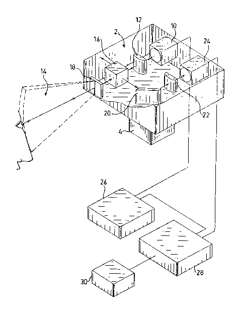
Fig. 1 is a partially pictorial-partially block diagram
illustration of apparatus for maintaining alertness constructed
and operative in accordance with a preferred embodiment of the
present invention; and
Fig~ 2 is a partially schematic, partially block diagram,
illustration of electronic circuitry useful in the present
invention~
,
. . , ~ . . .
' , ` .
:,, ,

~2~
DETAILED DESCRIPTION OF A PREFERRED EMBODIMENT
Reference is now made to Fig. 1, which illustrates a
preferred embodiment of the present invention including scanning
platform 2 which is typically mounted and driven by means of a
motor 4 for scanning rotation in a horizontal plane with respect
~o a reference mounting surface, such as the dashboard of a
vehicle. A radiation source 1~, is mounted onto pla~form 2~
sypically comprises a laser diode or an infrared emitting diode
nnd emits radiation via a collimating lens 12, such as a
cylindrical lens, so as to define a fan 14 of radiation disposed
typically in a vertical plane.
The radiation output via collimating cylindrical lens
1~ typically passes through a beam splitter 16 of conventional
construotion, which is operative to transmit a part of the beam
through an IR filter 18, and to reflect the remainder.
Most of the light transmitted in fan 14 via filter 18
is reflected in a diffuse manner from the various surroundings.
Light, within a given range of angles, impinging on the retina
through the cornea of an operator's eye is retrorePlected back in
tha direction from which it impinged on the cornea.
Retroreflected light received via the cornea impinges
on beam splitter 16 via filter 18 and is reflected by beam
splitter 16, via a mirror 2~ and a cylindrical or convex lens 22
to an infra-red detector 24, such as a photovoltaic silicon PN
detector.
It is appreciated that all of the apparatus described
above is mounted onto scanning platform 2.
:
:,

Radiation source 10 receives electr:ical power fron
emitter electronic circuitry 26, which ls illustrated in Fig. 2,
causing source 1~ to transmit IR pulses at high frequency or in a
continuous wave form.
When the operator's eye is directed within a suitable
range of directions with respect to the radiation source. a
retroreflected IR pulse train or continuous wave, as the case may
be, is received by detector 24 and transmitted to detector
electronic circuitry 28, which is illustrated in Fig. 2. This
GirCUitry receives timing inputs from emitter electronic
circuitry 26 and senses when anticipated retroreflected signals
are not received within a predetermined time range. The absence
of such retroreflected signals may indicate that the operator has
closed his eyes, or looked outside of a predetermined permitted
viewing rnnge. When appropriate, circuitry 28 produces an alarm
indicntion to a warning device 3~, such as an audio alarm.
Operation of the warning device 30 may be terminated
when the retroreflected light is once again received by detector
24.
Reference is now made to Fig. 2 which illustrates
electronic circuitry employed in the apparatus of Fig. 1. An
oscillator 40, typically operating at l~KHz, provides an output
to n power transistor 42, which provides a desired pulse output
to a laser diode 44, which serves as radiation source 1~ (Fig.
1) .
The output of oscillator 40 is also provided via a flip
flop circuit 46 to the base of a transistor 48, which receives
the output oP IR detector 24 (Fig. 1) via an operational

~85~
amplifier 5~. Transistor 48 thus acts as a switch, permitting the
output from operational amplifier 5~ to pass only when it is
received within a predetermined coincidence time of the
tr~smission of an IR pulse by laser diode 44, thereby to prevent
~alse detection due to spurious IR sources.
The output from transistor 48 is supplied via an
operational amplifier 52 to a comparator 54, which compares it
with n predetermined reference and provides a RESET input to a
counter 6~ and to a DFF circuit 64. A free oscillator 58,
typicnlly operating at 3~ H~ provides a clocking input to coùnter
.
The RESET input is provided by comparator 54 whe~
retroreflected radiation is sensed by detector 24. Should counter
6~ count up to a predetermined threshold count without being
reset in response to detection of retroreflected radiation, such
count output causes state logic circuitry 62, which receives
counter outputs, to activate an alarm 66, such as an audio alarm,
via the DFF circuitry 64.
DFF circuitry 64 is operative to terminate the
operation of alarm 66, when it receives the RESET signal,
in~icative of sensed retroreflected radiation.
It will be appreciated by persons skilled in the art
thnt the present invention is not limited by what has been
pnrticularly shown and described hereinabove. Rather the scope
o~ the present invention is defined only by the claims which
follow:

Dessin représentatif
Une figure unique qui représente un dessin illustrant l'invention.
États administratifs

2024-08-01 : Dans le cadre de la transition vers les Brevets de nouvelle génération (BNG), la base de données sur les brevets canadiens (BDBC) contient désormais un Historique d'événement plus détaillé, qui reproduit le Journal des événements de notre nouvelle solution interne.

Veuillez noter que les événements débutant par « Inactive : » se réfèrent à des événements qui ne sont plus utilisés dans notre nouvelle solution interne.

Pour une meilleure compréhension de l'état de la demande ou brevet qui figure sur cette page, la rubrique Mise en garde , et les descriptions de Brevet , Historique d'événement , Taxes périodiques et Historique des paiements devraient être consultées.

Historique d'événement

Description Date
Inactive : CIB de MCD 2006-03-11
Le délai pour l'annulation est expiré 2000-07-10
Lettre envoyée 1999-07-09
Accordé par délivrance 1991-07-09

Historique d'abandonnement

Il n'y a pas d'historique d'abandonnement

Historique des taxes

Type de taxes Anniversaire Échéance Date payée
TM (catégorie 1, 6e anniv.) - petite 1997-07-09 1997-07-07
TM (catégorie 1, 7e anniv.) - petite 1998-07-09 1998-07-07
Titulaires au dossier

Les titulaires actuels et antérieures au dossier sont affichés en ordre alphabétique.

Titulaires actuels au dossier
RASAAT
Titulaires antérieures au dossier
DAN MORAN
YONATAN GERLITZ
Les propriétaires antérieurs qui ne figurent pas dans la liste des « Propriétaires au dossier » apparaîtront dans d'autres documents au dossier.
Documents

Pour visionner les fichiers sélectionnés, entrer le code reCAPTCHA :


Pour visualiser une image, cliquer sur un lien dans la colonne description du document. Pour télécharger l'image (les images), cliquer l'une ou plusieurs cases à cocher dans la première colonne et ensuite cliquer sur le bouton "Télécharger sélection en format PDF (archive Zip)" ou le bouton "Télécharger sélection (en un fichier PDF fusionné)".

Liste des documents de brevet publiés et non publiés sur la BDBC .

Si vous avez des difficultés à accéder au contenu, veuillez communiquer avec le Centre de services à la clientèle au 1-866-997-1936, ou envoyer un courriel au Centre de service à la clientèle de l'OPIC.


Description du
Document 
Date
(aaaa-mm-jj) 
Nombre de pages   Taille de l'image (Ko) 
Abrégé 1993-10-21 1 31
Revendications 1993-10-21 3 79
Dessins 1993-10-21 2 48
Page couverture 1993-10-21 1 13
Description 1993-10-21 6 149
Dessin représentatif 2000-07-26 1 22
Avis concernant la taxe de maintien 1999-08-09 1 179
Taxes 1998-07-07 1 38
Taxes 1997-07-07 1 32
Taxes 1995-07-04 1 36
Taxes 1994-07-08 1 30
Taxes 1996-07-04 1 24
Taxes 1993-06-30 1 25