Sélection de la langue

Search

Sommaire du brevet 1286147 

Énoncé de désistement de responsabilité concernant l'information provenant de tiers

Une partie des informations de ce site Web a été fournie par des sources externes. Le gouvernement du Canada n'assume aucune responsabilité concernant la précision, l'actualité ou la fiabilité des informations fournies par les sources externes. Les utilisateurs qui désirent employer cette information devraient consulter directement la source des informations. Le contenu fourni par les sources externes n'est pas assujetti aux exigences sur les langues officielles, la protection des renseignements personnels et l'accessibilité.

Disponibilité de l'Abrégé et des Revendications

L'apparition de différences dans le texte et l'image des Revendications et de l'Abrégé dépend du moment auquel le document est publié. Les textes des Revendications et de l'Abrégé sont affichés :

  • lorsque la demande peut être examinée par le public;
  • lorsque le brevet est émis (délivrance).
(12) Brevet: (11) CA 1286147
(21) Numéro de la demande: 1286147
(54) Titre français: PROJECTILE A CEINTURE DE RENFORCEMENT SUR SA DOUILLE
(54) Titre anglais: PROJECTILE HAVING A DRIVING BAND ON ITS CASING
Statut: Périmé et au-delà du délai pour l’annulation
Données bibliographiques
(51) Classification internationale des brevets (CIB):
  • F42B 14/02 (2006.01)
(72) Inventeurs :
  • KRUSE, HEINZ-JOSEF (Allemagne)
  • KARIUS, KLAUS D. (Allemagne)
(73) Titulaires :
  • RHEINMETALL GMBH
(71) Demandeurs :
  • RHEINMETALL GMBH (Allemagne)
(74) Agent: SMART & BIGGAR LP
(74) Co-agent:
(45) Délivré: 1991-07-16
(22) Date de dépôt: 1987-09-02
Licence disponible: S.O.
Cédé au domaine public: S.O.
(25) Langue des documents déposés: Anglais

Traité de coopération en matière de brevets (PCT): Non

(30) Données de priorité de la demande:
Numéro de la demande Pays / territoire Date
P 36 30 000.4-15 (Allemagne) 1986-09-03

Abrégés

Abrégé anglais


ABSTRACT
A projectile (1) has a casing (2) with a driving band
(3) thereon the latter having grooves (31, 32, 33, 34) that serve
to accommodate the driving band material that is sheared off rear-
wards when the projectile (1) passes through the barrel of the
weapon. In order to achieve a reduction of the mean guide band
pressure and better sealing against gas pressure, particularly
when very thin walled casings are used, there is at least one
groove provided as a pressure relieving groove (35) at least in
those places in the vicinity of the guide band (3), and which
maximum stress of the projectile casing (2) occurs in a radial
direction. It is preferred that the pressure relieving groove
(35) be of a width that is > 4 mm.

Revendications

Note : Les revendications sont présentées dans la langue officielle dans laquelle elles ont été soumises.


26130-51
THE EMBODIMENTS OF THE INVENTION IN WHICH AN EXCLUSIVE
PROPERTY OR PRIVILEGE IS CLAIMED ARE DEFINED AS FOLLOWS:
1. A projectile for firing from a gun barrel comprising: a
projectile body having radial and longitudinal directions; a
rotating band disposed on said projectile body and having a width
in said longitudinal direction and including at least three band
rings; one of said band rings being located at each end of said
width of said rotating band; at least one material receiving
groove in said rotating band to accommodate rotating band material
sheared off during passage of said projectile through the gun
barrel; and at least one pressure relief groove located in a
region of said rotating band where said projectile body is
subjected to maximum stress in said radial direction, and wherein
said pressure relief groove and said material receiving groove
each have a width in said longitudinal direction; the width of
said pressure relief groove being greater than the width of said
material receiving groove.
2. A projectile for firing from a gun barrel according to
claim 1, wherein said width of said pressure relief groove is
greater than 4 mm.
3. A projectile for firing from a gun barrel according to
claim 2, wherein said width of said pressure relief groove is in
the range of 6 to 20 mm.
4. A projectile for firing from a gun barrel according to

6 26130-51
claim 1, said rotating band further comprising at least four band
rings and having at least two material receiving grooves, wherein
said pressure relief groove is located between said two material
receiving grooves and is separated from each of said material
receiving grooves by a respective band ring.
5. A projectile for firing from a gun barrel wherein said
projectile has a wall thickness whose ratio to the caliber of the
gun barrel is at the most 0.05, said projectile comprising: a
projectile body having radial and longitudinal directions; a
rotating band disposed on said projectile body having a width in
said longitudinal direction and including a plurality of band
rings; one of said band rings being located at each end of said
width of said rotating band; at least one material receiving
groove in said rotating band to accommodate rotating band material
sheared off during passage of said projectile through the gun
barrel; and at least one pressure relief groove located in a
region of said rotating band where said projectile body is
subjected to maximum stress in said radial direction, and wherein
said pressure relief groove and said material receiving groove
each have a width in said longitudinal direction; the width of
said pressure relief groove being greater than the width of said
material receiving groove.
6. A projectile for firing from a gun barrel according to
claim 5, wherein said width of said pressure relief groove is
greater than 4 mm.

7 26130-51
7. A projectile for firing from a gun barrel according to
claim 6, wherein said width of said pressure relief groove is in
the range of 6 to 20 mm.
8. A projectile for firing from a gun barrel according to
claim 5, said rotating band further comprising at least four band
rings and having at least two material receiving grooves, wherein
said pressure relief groove is located between said two material
receiving grooves and is separated from each of said material
receiving grooves by a respective band ring.

Description

Note : Les descriptions sont présentées dans la langue officielle dans laquelle elles ont été soumises.

4~
- 1 - 26130-51
The present invention relates to a projectile having a
driving bend arranged on its casing.
In spin-stabilized projectiles, the projectiles have one
or, for reasons of stress or deformation, sometimes a plurality of
driving bands arranged one behind the other. The diameter of
these driving bands is such that when the projectile passes
through the barrel they are forced into the rifling grooves.
It is known per se that circular grooves can be incor-
porated in the driving band, such grooves serving to accommodate
the driving band material that is sheared off to the rear (see,
for example, US-PS 3,910,194). Usually, the width of such grooves
is no greater than 4 mm. The drive bands can consist of copper,
soft iron, or plastic.
In these known driving bands, radial contact between the
barrel and the driving band exists only through the annular sec-
tions between the grooves. This contact exerts a radial pressure
on the projectile casing 1 (driving band pressure).
Especially in the case of thinner projectile casings, in which,
normally, the ratio between the wall thickness of the projectile
casing to the calibre of the barrel is ~ 0.05, the projectile is
particularly sensitive to radial pressure, since at certain places
that depend on the projectile geometry, this can lead to
particularly great material stress. Because of this, the projec-
tile casing may be compressed inwards and the sealing against the
propellant gases, normally ensured by the driving band, is no
longer guaranteed.
For this reason, the present invention aims to provide

````- 1~6~4~
2 26130-51
a projectile of the type described, in which, primarily when thin-
walled casings are used, it is possible to achieve a reduction of
the mean driving band pressure as well as better sealing against
gas pressure.
The invention provides a projectile for firing from a
gun barrel comprising: a projectile body having radial and
longitudinal directions; a rotating band disposed on said
projectile body and having a width in said longitudinal direction
and including at least three band rings; one of said band rings
being located at each end of said width of said rotating band; at
least one material receiving groove in said rotating band to
accommodate rotating band material sheared off during passage of
said projectile through the gun barrel; and at least one pressure
relief groove located in a region of said rotating band where said
projectile body is subjected to maximum stress in said radial
direction, and wherein said pressure relief groove and said
material receiving groove each have a width in said longitudinal
direction; the width of said pressure relief groove being greater
than the width of said material receiving groove.
The invention also provides a projectile for firing from
a gun barrel wherein said projectile has a wall thickness whose
ratio to the caliber of the gun barrel is at the most 0.05, said
projectile comprising: a projectile body having radial and longi-
tudinal directions; a rotating band disposed on said projectile
body having a width in said longitudinal direction and including a
plurality of band rings; one of said band rings being located at
each end of said width of said rotating band; at least one

1~3614~
2a 26130-51
material receiving groove in said rotating band to accommodate
rotating band material sheared off during passage of said
projectile through the gun barrel; and at least one pressure
relief groove located in a region of said rotating band where said
projectile body is subjected to maximum stress in said radial
direction, and wherein said pressure relief groove and said
material receiving groove each have a width in said longitudinal
direction; the width of said pressure relief groove being greater
than the width of said material receiving groove.
The underlying concept of the present invention is the
provision of a relieving groove at those locations in the driving
band where there is increased stress on the projectile casing in
the radial direction. Clearly at the location of the or each
pressure relieving groove, there will be no radial pressure on the
projectile casing generated by contact with the barrel.
The axial extent of the relieving grooves depends on the
rigidity of the projectile casing and in the case of artillery
projectiles having metal driving bands, should be ~ 4 mm.
The invention will be described in greater detail below,
by way of example only, with reference to the accompanying
drawings wherein:
Figure 1 is a partially sectioned view of a projectile,
known per se, with a guide band according to the present
invention;
Figure 2 is an enlarged detailed sectional view of a
guide band according to the present invention, arranged on the
projec-

614~
- 3 - 26130-51
tile casing; and
Figure 3 shows the pressure distribution along the driving
band of figure 2.
In figure 1, the projectile 1, has a casing 2, with a
drive band 3. The diameter of the driving band 3 is such that
when the projectile passes through the barrel its bands will be
pressed completely into the rifling grooves. Spin is transmitted
to the projectile through the lands and at the same time a seal
against the powder gases is provided. In the area of the driving
band 3, the projectile 1 has a space 4, in which, for example, a
retarder parachute (notshown herein) can be accommodated. In
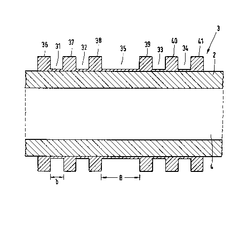
figure 2, the projectile casing 2 and the driving band 3 are shown
in enlarged scale. The grooves numbered 31 to 34 serve in known
manner to accommodate the driving band material that is sheared
off rearwards when the projectile passes through the barrel.
There is radial contact between the barrel and the driv-
ing band 3 only on the guide band rings 36 to 41.
Figure 3 shows an example of the pressure distribution
along the driving band. The distance a in millimeters from the
forward edge of the guide band is shown on the abcissa, and the
driving band pressure P in bars is shown on the ordinate. The
broken line curve 300 shows the driving band pressure distribution
for a driving band without grooves according to the projectile
construction incorporating a hollow space 4 as is shown in figure
1. It can be seen quite plainly that maximum driving band pres-
sure occurs in the approximate centre of the driving band.
As a consequence of this, a relieving groove 35 is made

~ 36~47
- 4 - 26130-51
in this area. The width B of the groove 35 should be greater than
4 mm.
In artillery projectiles, the width B will be approx-
imately between 6 and 20 mm, depending on the type of projectile.
At all events it must be taken into account that the total width
of the driving band lands or rings in projectiles of this kind
will amount to approximately 20 mm (typically, driving bands are
38 to 40 mm wide).
The stepped curve 301 in figure 3 shows the approximate
pressure distribution of the driving band 3 of figure 2. Because
of the relieving groove 35, driving band pressure in this area has
quite clearly been reduced.
It is, of course, understood that a plurality of reliev-
ing grooves can be provided depending on the driving band pressure
distribution that has been determined.

Dessin représentatif
Une figure unique qui représente un dessin illustrant l'invention.
États administratifs

2024-08-01 : Dans le cadre de la transition vers les Brevets de nouvelle génération (BNG), la base de données sur les brevets canadiens (BDBC) contient désormais un Historique d'événement plus détaillé, qui reproduit le Journal des événements de notre nouvelle solution interne.

Veuillez noter que les événements débutant par « Inactive : » se réfèrent à des événements qui ne sont plus utilisés dans notre nouvelle solution interne.

Pour une meilleure compréhension de l'état de la demande ou brevet qui figure sur cette page, la rubrique Mise en garde , et les descriptions de Brevet , Historique d'événement , Taxes périodiques et Historique des paiements devraient être consultées.

Historique d'événement

Description Date
Inactive : Demande ad hoc documentée 1994-07-16
Le délai pour l'annulation est expiré 1994-01-18
Lettre envoyée 1993-07-16
Accordé par délivrance 1991-07-16

Historique d'abandonnement

Il n'y a pas d'historique d'abandonnement

Titulaires au dossier

Les titulaires actuels et antérieures au dossier sont affichés en ordre alphabétique.

Titulaires actuels au dossier
RHEINMETALL GMBH
Titulaires antérieures au dossier
HEINZ-JOSEF KRUSE
KLAUS D. KARIUS
Les propriétaires antérieurs qui ne figurent pas dans la liste des « Propriétaires au dossier » apparaîtront dans d'autres documents au dossier.
Documents

Pour visionner les fichiers sélectionnés, entrer le code reCAPTCHA :


Pour visualiser une image, cliquer sur un lien dans la colonne description du document. Pour télécharger l'image (les images), cliquer l'une ou plusieurs cases à cocher dans la première colonne et ensuite cliquer sur le bouton "Télécharger sélection en format PDF (archive Zip)" ou le bouton "Télécharger sélection (en un fichier PDF fusionné)".

Liste des documents de brevet publiés et non publiés sur la BDBC .

Si vous avez des difficultés à accéder au contenu, veuillez communiquer avec le Centre de services à la clientèle au 1-866-997-1936, ou envoyer un courriel au Centre de service à la clientèle de l'OPIC.


Description du
Document 
Date
(aaaa-mm-jj) 
Nombre de pages   Taille de l'image (Ko) 
Page couverture 1993-10-21 1 12
Abrégé 1993-10-21 1 17
Dessins 1993-10-21 2 27
Revendications 1993-10-21 3 74
Description 1993-10-21 5 148
Dessin représentatif 2001-07-17 1 16