Note : Les descriptions sont présentées dans la langue officielle dans laquelle elles ont été soumises.
1~8~ 2
A DEVICE FOR THE SEPARABLE CONNECTION OF
TWO PREFABRICATED PARTS
The present invention relates to a device for
connecting two prefabricated parts, in particular of wood,
these having two elements that are installed in suitable
grooves or slots in the aforesaid parts, and which can be
secured therein, these elements having barbs on their side
surfaces and hook heads that can be engaged one within the
other, these being arranged laterally extending on blades,
which blades are formed on those sides of the elements of the
device that are proximate to each other when connected, the
hook heads of the two interacting elements engaging in each
other when in the connected position.
A device oE the kind specified heretofore is
described in AT-PS 373 046. In this known device, there is one
hook head on the blade of each element of the device, and the
stability of the connection is limited by the holding power
that can be achieved by the use of such a lateral or
arrow-shaped hooX head. In addition to this, in this known
device the hook head is so configured as to be rounded at its
extremities and thus, when the elements of the device are
assembled, there may be point contact, and this can result in
large frictional forces, so that when the elements of the
device are assembled they may jam or seize. Similar
difficulties or disadvantages can occur in the device described
in CH-PS 616 993, which differs from the previously mentioned
~Z86872
device in that the hook heads, essentially following to the
plane exterior of the elements of the device, extend to one
side, each such element being provided with one such hook head,
the hook heads engaging with each other in that two identically
configured elements of the device are joined in a position in
which they are turned by 180 degrees relative to each other.
In the device according to the present invention each
of the two elements of the device has on its blade portion at
least two hook heads, these being adjacent to each other and
separated from each other by a distance that corresponds at
least to the length of a hook head; the hook heads each have a
hook-over surface that ends obliquely on both of its sides.
It is advantageous for the precise mutual positioning
of the two elements that interact to form the complete device
that within the area situated immediately after the hook heads,
in which in the connected position of the two elements the hook
heads of the other element come to rest, there be locking tabs
that are offset to one side relative to the hook heads. These
tabs are either bendable or movable, each forming a side stop
for one of the hook heads of the other element of the device.
These locking tabs may be bent or moved out of the surface of
the element as may be required, in order that, as desired, the
lateral shifting of the one element relative to the other
element of the device can be limited to one side or to the
other. As a rule, in order that the elements of the device may
be installed in t~e components that are to be joined, grooves
are provided, into which the elements can be introduced. It is
12868 ~ 2
advantageous that the grooves be so produced that their bottoms
follow a circular shape that is matched to the outer contour of
the elements and can be produced by the routers widely used by
cabinet makers. The elements of the device will hold very well
in such grooves because of the barbed sections that are
provided on the side surfaces of the elements. As a rule, glue
or other adhesive is applied to the grooves in order to enhance
the attachment of the elements within the grooves. In order to
further improve this anchoring effect, in a further embodiment
of the device according to the present invention there are
steps on the side ends of the elements of the device on the
side that incorporates the blade. Thus, the elements of the
device can be additionally secured by screws, these being
screwed into the components that are to be joined, adjacent to
the elements of the device, at the extremities of the elements
themselves, and coming to rest such that the undersides of the
heads of the screws are against the steps. It is advantageous
for the installation of the elements of the device if, on the
side of the element that is remote from the blade, there are
points, since, ~hen the elements of the device are being
installed in the components, these points make positioning of
the elements very simple. This secures the elements of the
device in position until the screws and/or the adhesive becomes
fully effective.
The present invention will be described in greater
detail below on the basis of embodiments shown in the drawings
appended hereto. The invention is not restricted to the
-- 3 --
128~'7;~
examplary embodiments shown in these drawings. In drawings
which illustrate embodiments of the invention,
Figure 1 is a partial cross-section rear view of one
of the two elements that together form one embodiment of the
device according to the present invention, the element being
installed in one of two components to be joined together;
Figure 2 is a front view that shows an element of the
device installed in a suitably grooved panel;
Figure 3 is a cross-section of the line I-I in
Figure l;
Figure 4 is a cross-section of the line II-II in
Figure 2,
Figures 5 to 9 show various possibilities for using
the device according to the present invention in panels that
are to be joined by using such a device; these figures are
partially cut-away cross-sections, viewed from the face edges
of the panels;
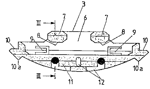
Figure 10 is a front view of an element of the device
configured according to the present invention;
Figure 11 is a cross-section of the line III-III in
Figure 10;
Figure 12 is a top plan view of the element shown in
Figure 10;
Figure 13 shows a device configured according to the
present invention, in which two identically configured elements
are locked in position, hooked into each other;
-- 4 --
~21~6~
Figure 14 is a cross-section of the line IV-IV in
Figure 13.
In the drawings, Figures 1 and 3 show an element 3
inserted into a component 1, Figures 2 and 4 show an
identically configured element 3 that has been inserted,
rotated through an angle of 180 degrees, into a second
component 2. Grooves that are approximately semicircular, are
provided in the components 1, 2 to accommodate the devices 3.
In the case that is shown, the components are panels. An
element of a device of this kind is shown at larger scale in
Figures 10, 11, and 12, and Figures 13 and 14 show a device
that has been formed by combining two such elements. Each of
the elements 3 of the device has a blade 6 on which at least
two projecting hook heads 7 are arranged. These hook heads are
arranged so as to be spaced apart from each other by a distance
that corresponds to at least the length of a hook head. On
each of the hook heads 7 there is a hook-over surface 8 that
ends obliquely on both sides such that when two elements of the
device are joined together and the two hook heads are engaged
with each other, the area contact on the obliquely ending
hook-over surfaces results in the possibility of easy (lateral)
shifting. In the embodiment shown there are two hook heads,
although it is possible to provide a greater number, for
example, three or four, of such hook heads on each blade 6.
The elements 3 of the device have lock tabs 9 which,
as shown in Figure 12, can be bent out of the blade 6 in order
to form a stop for a hook head of the second element of the
~
12~3~87Z
device, which functions toge~her with the first element of the
device. Viewed in the direction 14 in which the elements of a
device are connected, the lock tabs 9 lie in the area which is
located immediately after the hook heads 7 of the element 3 of
the device, laterally displaced relative to the hook heads 7
and thus form the lateral stops mentioned heretofore, which
interact with the hook heads and thus fix the mutual position
of the two elements 3 of the device in the lateral direction.
Steps 10 are provided at the side ends of the
elements 3, on the side of these elements that incorporates the
blade 6. Screws 5, which in the embodiment illustrated in
Figures 1 to 4 are shown as round-head screws and which are
screwed into the components 1,2 that are to be joined, can come
into contact with these steps at, the underside of the screw
heads, which results in a particularl~ solid installation of
the elements 3 in the components 1 and 2. In addition, barbed
or serrated sections 11 and glue channels 12 are provided on
the side surfaces of the elements 3 so as to fix said elements
within the components 1 and 2. The sections ll--both directly
and in conjunction with the glue applied to the grooves
4--enhance the attachment of the elements of the device to the
walls of the grooves, and the glue channels 12 effect or
enhance the even distribution of the glue that has been applied
to the grooves 4 on insertion of the elements 3 of the device
into the components 1, 2. In order to fix the position of
these components during insertion of the elements 3 of the
device into the components 1, 2 until such time as the glue or
~ ~ .
~2~ 2
the screws 5 can ensure a good joint, points lOa can be
provided on that side of the device element that is remote from
the blade 6, on the edge of this, as is indicated in the
drawing in the area of the step 10. However, it is possible to
dispense with points of this kind, in which case, for example,
the edge of the element 3 of the device can be so configured as
to continue as a semicircle right up to the ends.
If so desired, the lock tabs 9 can also be configured
so as to be movable.
Figures 5 to 9 show many possibilities for combining
the components 1 and 2 with devices as described herein, each
of the two elements of these being inserted into the components
that are to be joined and then being joined together.