Sélection de la langue

Search

Sommaire du brevet 1286925 

Énoncé de désistement de responsabilité concernant l'information provenant de tiers

Une partie des informations de ce site Web a été fournie par des sources externes. Le gouvernement du Canada n'assume aucune responsabilité concernant la précision, l'actualité ou la fiabilité des informations fournies par les sources externes. Les utilisateurs qui désirent employer cette information devraient consulter directement la source des informations. Le contenu fourni par les sources externes n'est pas assujetti aux exigences sur les langues officielles, la protection des renseignements personnels et l'accessibilité.

Disponibilité de l'Abrégé et des Revendications

L'apparition de différences dans le texte et l'image des Revendications et de l'Abrégé dépend du moment auquel le document est publié. Les textes des Revendications et de l'Abrégé sont affichés :

  • lorsque la demande peut être examinée par le public;
  • lorsque le brevet est émis (délivrance).
(12) Brevet: (11) CA 1286925
(21) Numéro de la demande: 1286925
(54) Titre français: BOUEE SONORE A CABLE SUR BOBINOIR
(54) Titre anglais: SONOBUOY CABLE PACK
Statut: Périmé et au-delà du délai pour l’annulation
Données bibliographiques
(51) Classification internationale des brevets (CIB):
  • B63B 22/10 (2006.01)
  • B63B 22/00 (2006.01)
(72) Inventeurs :
  • HILL, MURRAY O. (Canada)
(73) Titulaires :
  • HER MAJESTY THE QUEEN, IN RIGHT OF CANADA, AS REPRESENTED BY THE MINISTE
(71) Demandeurs :
  • HER MAJESTY THE QUEEN, IN RIGHT OF CANADA, AS REPRESENTED BY THE MINISTE (Canada)
(74) Agent: JOHN LAMBLAMB, JOHN
(74) Co-agent:
(45) Délivré: 1991-07-30
(22) Date de dépôt: 1988-05-26
Licence disponible: S.O.
Cédé au domaine public: S.O.
(25) Langue des documents déposés: Anglais

Traité de coopération en matière de brevets (PCT): Non

(30) Données de priorité de la demande: S.O.

Abrégés

Abrégé anglais


ABSTRACT
A sonobuoy comprising: a sonobuoy body; a main cable
having a proximal end secured to the body and a distal end; a
spool on which the cable is wound from the distal end toward the
proximal end; and release means securing the spool to the body,
and operative in response to immersion in water to release the
spool from the body.

Revendications

Note : Les revendications sont présentées dans la langue officielle dans laquelle elles ont été soumises.


THE EMBODIMENTS OF THE INVENTION IN WHICH AN EXCLUSIVE
PROPERTY OR PRIVILEGE IS CLAIMED ARE DEFINED AS FOLLOWS:
1. A sonobuoy, comprising: a sonobuoy body; a main cable
having a proximal end secured to the body and a distal end; a spool
on which the cable is wound from the distal end toward the proximal
end; and release means, securing the spool to the body and operative
in response to immersion in water, for releasing the spool from the
body, the release means including at least one pin secured to the
body and extending into an opening in the spool, and retainer means
for releasably securing the pin in the opening, the retainer means
including retaining clips engageable with the pin and a water
soluble band holding the clips in engagement with the pin.
2. A sonobuoy according to claim 1, including a compliance
cord secured to the body and to the cable at a location spaced from
the proximal end.
3. A sonobuoy according to claim 1, including a lateral
cable connected to the main cable intermediate its ends and a
hydrophone secured to the lateral cable, the lateral cable being
wound on the spool with the main cable.
4. A sonobuoy according to claim 3, wherein the spool is
secured to the distal end of the main cable.
5. A sonobuoy according to claim 4, wherein the spool
comprises a ballast weight.
-5-

6. A sonobuoy according to claim 1, wherein the band is a
polyvinyl alcohol tape.
7. A sonobuoy according to claim 1 wherein the opening has
greater transverse dimensions than the pin.
8. A sonobuoy according to claim 7 wherein the retaining
clips, when coupled to the pin by the band, have greater transverse
dimensions that the opening.
9. A sonobuoy according to claim 8 wherein the retaining
clips are semi-cylindrical.
10. A sonobuoy according to claim 9 wherein the pin comprises
a tapered head.
-6-

Description

Note : Les descriptions sont présentées dans la langue officielle dans laquelle elles ont été soumises.

Z,r;
The present invel-ltiorl relates to a sonobuoy and more
particularly to a mechanism for deploying a hydropho,ne cable from
a sonobuoy.
It is conventional practice with sonobuoys to provide
the buoy with an outer housing that is jettisoned upon water
entry. This allows for the release of a hydrophone and the cable
connecting the hydrophone to the sonobuoy body. Elimination of
the extra housing is desirable, particularly in very small si~e
sonobuoys where space is at a premium. The objective of the
present invention is to provide an alternative cable pack and
release mechanism for a sonobuoy.
According to the present invention there is provided a
sonobuoy comprising:
a sonobuoy body;
a main cable having a proximal end secured to the body '
and a distal end; '
' a spool on which the cable is wound from the distal end
toward the proximal end; and
release means securing the spool to the body, and
operative in response to immersion in water to release the spool
from the body~
On water entry, the release means acts to release the
spool from the sonobuoy body, thus unwinding the main cable as the
spool falls away from the body.
In preferred embodiments, a hydrophone i5 secured to the
main cable by a lateral cable to provide a downrigger suspension ,
for the hydrophone.
In the accompanyiny drawings, which illustrate an
- ~ .
~, .

~ 2~692`~
xemplary embodiment of the present invention:
Figure 1 is a pictorial representation of a sonobuoy
according to the present invention in a deployed state;
Figure 2 is a side elvation of the sonobuoy before
deployment;
Figure 3 is a view along line III-III of Figure 2;
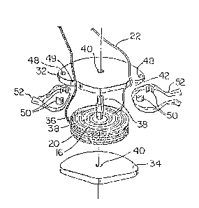
Fiyure 4 is an exploded view of the cable pack of the
sonobuoy; and
Figure S is an exploded view of the release mechanism
for the cable pack.
Referring to the drawings, and particularly to Figure 1,
there is illustrated a sonobuoy 10 having a body 12 and a float
14. The sonobuoy is designed to float at the surface of a body of
water as illustrated in Figure 1. A main cable 16 has a proximal
end secured to the body 12 of the sonobuoy 10 and a distal end
connected to a spool 18 that acts, in the deployed state shown, as
a ballast weight. Adjacent the body 12, the main cable 16 is
paralleled by a compliance 20 that serves at least partially to
isolate the main cable from wave induced motion of the body 12.
Adjacent the distal end of the cable 16 is a lateral
cable 22 that is connected to a neutrally bouyant hydrophone 24.
The effect of the combined main cable 16 with the ballast
weight/spool 18 and lateral cable 22 is a downrigger type
suspension for the hydrophone 24 that serves to isolate the . -
hydrophone from wave induced motions of the body 12.
Before deployment of the hydrophone 24/ the spool 18,
cables 16 and 22 and compliance 20 are contained within a cable
,., ~ .: : , . . .

3~S
pack 26 mounted on the bottom end of the sonobuoy body 12. This
.is illustrated most particularly in Figure 2. As shown, the
sonobuoy 24 is contained within a recess 28 in the bottom of the
body 12 and held in place by the spool 18 that is held on the
bottom end of the body 12 by two release mechanisms 30.
As illustrated most partic:ularly in Figure 4, the spool
18 consists of an upper flange 32, a lower flange 34 and a core
pin 36. The core pin 36 has hollow ends 38 that extend through
respective bores in the flanges 32 and 34 and are riveted as
illustrated in Figure 2 to hold the flanges in place. As :
illustrated most particularly in Figure 3, each of the flanges is
configured.as the 90 segment of a circle to match the
configuration of the sonobuoy body 12.
The lateral cable 24 is connected to the hydrophone and
passes around the upper flange 32, through a notch 42 for
connection to the main cable 16, which is wound on the spool~ The
compliance 20 is wound on the spool together with the proximal
section of the main cable 16. Both pass through a notch 44 in the
edge of the upper flange 32 for connection to the sonobuoy body
12.
The release mechanisms retaining the cable pack on the .
: sonobuoy body 12 are illustrated in Figures 2 through 5. These
consist of retaining pins 46 secured to the body 12 and projecting
through bores 48 in the upper flange 32. The pins 46 are headed
with tapered heads as shown in Figures 2 and 5. Two retaining ~:
clips 50 are engaged with each of the pins 46. The clips are
semi-cylindrical with an inner configuration matching the shape of
the pin 46 and an outer diameter that is greater than the diameter
: . -. . . :. :.. : . .. ,, ........ , . .. :

~ ~369X.~;
of the holes 48. To retain the clips 50 in place, a strip of
polyvinyl alcohol tape 52 is wrapped around the two clips and tied
in a knot as illustrated in Figure 5. The tape is water soluble
so that upon water entry, the tapes dissolve, allowing the clips
50 to be jettisoned and the cable pack 5h to fall off the pins 46.
The spool 18 then unwinds as it falls away ~rom the sonobuoy body
12 to deploy the main cable 16 and ultimately the lateral cable 22
and hydrophone 24. The hydrophone is released from its recess 28
in the bottom of body 12 when the spool drops off the pins 46.
While one embodiment of the present invention has been
described in the foregoing, it is to be understood that other
embodiments are possible within the scope of the present
invention. For example, the described embodiment incorporates the
use of two release mechanisms, each including a retaining pin, a
pair of retaining clips and a strip of P~A tape. In other
embodiments, other numbers o~ these components can be used, for
example a single pin 46 and one or more rètaining clips 50. It is
also possible to construct a release mechanism that will release
on impact with the water or that uses only a water soluble release
mechanism.
:
~:.
: . ~ ' , ' ' ',: '. . .' ' ' -

Dessin représentatif
Une figure unique qui représente un dessin illustrant l'invention.
États administratifs

2024-08-01 : Dans le cadre de la transition vers les Brevets de nouvelle génération (BNG), la base de données sur les brevets canadiens (BDBC) contient désormais un Historique d'événement plus détaillé, qui reproduit le Journal des événements de notre nouvelle solution interne.

Veuillez noter que les événements débutant par « Inactive : » se réfèrent à des événements qui ne sont plus utilisés dans notre nouvelle solution interne.

Pour une meilleure compréhension de l'état de la demande ou brevet qui figure sur cette page, la rubrique Mise en garde , et les descriptions de Brevet , Historique d'événement , Taxes périodiques et Historique des paiements devraient être consultées.

Historique d'événement

Description Date
Inactive : CIB de MCD 2006-03-11
Inactive : Demande ad hoc documentée 1996-07-30
Le délai pour l'annulation est expiré 1996-01-30
Lettre envoyée 1995-07-31
Accordé par délivrance 1991-07-30

Historique d'abandonnement

Il n'y a pas d'historique d'abandonnement

Titulaires au dossier

Les titulaires actuels et antérieures au dossier sont affichés en ordre alphabétique.

Titulaires actuels au dossier
HER MAJESTY THE QUEEN, IN RIGHT OF CANADA, AS REPRESENTED BY THE MINISTE
Titulaires antérieures au dossier
MURRAY O. HILL
Les propriétaires antérieurs qui ne figurent pas dans la liste des « Propriétaires au dossier » apparaîtront dans d'autres documents au dossier.
Documents

Pour visionner les fichiers sélectionnés, entrer le code reCAPTCHA :


Pour visualiser une image, cliquer sur un lien dans la colonne description du document. Pour télécharger l'image (les images), cliquer l'une ou plusieurs cases à cocher dans la première colonne et ensuite cliquer sur le bouton "Télécharger sélection en format PDF (archive Zip)" ou le bouton "Télécharger sélection (en un fichier PDF fusionné)".

Liste des documents de brevet publiés et non publiés sur la BDBC .

Si vous avez des difficultés à accéder au contenu, veuillez communiquer avec le Centre de services à la clientèle au 1-866-997-1936, ou envoyer un courriel au Centre de service à la clientèle de l'OPIC.


Description du
Document 
Date
(aaaa-mm-jj) 
Nombre de pages   Taille de l'image (Ko) 
Abrégé 1994-07-21 1 10
Dessins 1994-07-21 2 57
Revendications 1994-07-21 2 58
Description 1994-07-21 4 148
Dessin représentatif 2001-11-14 1 12
Taxes 1993-06-02 2 72
Taxes 1994-05-26 2 118