Note : Les descriptions sont présentées dans la langue officielle dans laquelle elles ont été soumises.
128711q
[C248:17248:~GM] -1-
REMOTE MONITORING AND ALA~ SYSTE~I
FIELD OF THE INVENTION
This invention relates to monitoring systems, and more
particularly to a remote monitoring system using a radio
frequency link between a transmitter, which is carried by
a person or object being monitored, and a portable monitoring
receiver. The receiver detects signals from the transmitter
and produces alarms or displays information for various
emer~ency or status conditions associated with the person
or object being monitored.
BACKGROUND OF THE INVENTION
Many children are reported missing each year, either
from child abduction or simply from straying away fromparents
or guardians who are unaware of their being lost or in
danger. A child also may wander away and be lost for several
hours before being found by terrified parents, or parents
may lose track of a child in crowded surroundings unfamiliar
to the small child.
At the same time, caregivers for Alzheimers patients,
and others suffering from dementia resulting in the wandering
syndrome, experience difficulty in keeping track of those
requiring special care. Families and institutions alike
have expressed genuine concern for the well-being of the
~371~
1 handicapped, elderly and special patients requiring close
observation. Further, the bedridden have been reported to
often suffer from sensitive incontinence problems which
can aggravate existing symptoms and minimize overall comfort.
5- Swimming pool owners and those involved in recreational
activities near the water are well aware of the need for
water safety precautions. For instance, small children
may wander into the water without appreciating the dangers.
It is not always feasible nor is it reasonable to e~pect
that personal supervision of small children by a guardian
can always prevent water-related accidents from happening.
There is a need for a safety device that helps a
parent or guardian keep track of a person by constan.ly
monitoring his or her whereabouts and triggering an alarm
to alert the responsible parent or guardian whenever the
subject has encountered an emergency, strayed too far, or
is otherwise in danger. It has been proposed that such a
safety device include a transmitter worn by the subject and
a receiver carried by the parent, guardian or caregiver.
In a child monitoring situation, the receiver can be set
to monitor the child's whereabouts within a desired radius,
and if the child moves beyond the pre-set range, a beeper
and warning light on the receive~ alert the parent or
guardian. The beeper also can alert the guardian if the
transmitter is momentarily removed from the child, submerged
in water, or turned off. A call button on the transmitter
can be pressed if the child becomes lost or perceives
d~nger, such as if a stranger approaches- In a hospital
or rest home setting, a call button can be used to transmit
an alarm if a patient becomes ill or disorientation occurs.
The patient's whereabouts also can be constantly monitored.
- There is a need to monitor for awidevariety ofemergency
situations. For example, emergencies monitored can be
out-of-range, immersion, tampering with the transmitter,
breathing rate, as examples. Call signaling can be provided,
~2~71~
-3-
1 although this may not be considered to have the same
priority as other emergencies.
There is also a need to ensure that such a monitoring
device has an exceedingly high degree of rellability. For
instance, an alarm must be activated at the receiver with
essentially 100% accuracy whenever a monitored emergency
condition arises, regardless of interfering sources or
other similar~mQnit~rin~ systems in c}ose pro~imity. The
alarm also should be produced immediately when an emergency
is detected, since time is of the essence in most emergency
situations.
In addition, it is necessary to reduce the probability
of false alarms at the receiver. False alarms have been a
major annoyance with monitoring devices previously used in
experimental testing. These experimental units have
covered a wide geographical range to determine how and
whether local conditions will affect radio frequency
transmission. It has been learned that false alarms can
be produced from interference from ~I sources or electrical
noise or from other nearby electronic devices operating at
the same radio frequency- Even though interference may be
present from overlapping signals from other sources, false
alarms even in these situations should be minimized. False
alarms are not only annoying, but they are also a source of
possible misinformation- An emergency could be detected
at the receiver, only to have a later transmitted signal
changed by an interfering signal that indicatesthe emergency
has been corrected when, in fact, it has not. Alarm
failures also should be prevented- Alarm failure can be
caused by a second similar transmitter set at the same
frequency transmitting an identical address code signal which
becomessubstituted forthesignal from the firsttransmitter
This may cause the receiver for the first transmitter to
operate without producing an alarm when an alarm may be
necessary for an emergency situation.
7~14
--4
l It is also desirable to monitor signaIs from more
than one transmitter with a single receiver so that one
person can monitor the whereabouts of more than one subject
~ithout requiring multiple receivers. Transmitters worn by
t~o different subjects, for e~ample, should operate indepen-
dently on the same carrier frequency, but without producing
false alarms from interfering signals.
Remote monitoring devices also have a number of design
requirements which are difficult to achieve concurrently in
one small package. For example, in a radio frequency
monitorin~ system, it is desirable to obtain maximum po~er
transmission, within FCC limits, in order to ma~imize the
range over uhich the device is sensitive. There is also a
need for a high-sensitivity receiver ~hich can be produced
at a lotJ cost and operate with lo-.~ po-~er consu~ption an~
at low voltagesO In addition, there is a need for a safety
device combining the ability to operate ~lith lo~J-voltage
- digital electronics in the same small package and in close
proximity to high-po~er radio frequency energy. Both mus~
work together reliably, without interference or false
alarms, and still be made available in a small pac~age at
a low cost so the system can be affordable to everyone.
This invention provides an e~tremely reliable radio
frequency monitoring system which greatly reduces the
probability of false alarms or alarm failure, while ensuring
that necessary emergency alarms are immediately and reliably
transmitted to the receiver. The system constantly
monitors a variety of emergency and status condition
including out-of~range, anti-tampering, panic-alert~
immersion and wetness sensing, breathing rate, lo~-battery
condition, and the like- The system can independently
monitor these functions from more than one transmitter
with a single receiver operating on the same carrier
frequency substantially without interference, false alarms
or alarm failure. The invention also makes it possible to
`' . , ', ' ,': . ' , ' ' ' ' '
. .
. ,
.
~87~1A
--5--
1 combine maximum power radio frequency transmission in the
same small package and in close proximity to low-voltage
digital electronics at a reasonable cost. Range is increased
and receiver sensitivity to signals from the transmitter also
is increased when compared with radio frequency monitoring
systems operating under similar regulations.
In addition, the invention includes a custom digital
integrated circuit having utility;for a variety of situations
where remote monitoring is desirable. The system can be
used in monitoring children, the elderly in rest homes, or
those confined to prisons or detention facilities. It can
also be used as a water safety device, or for trac~ing the
whereabouts of a variety of moving objects.
SU~RY OF THE INVENTION
Briefly, the invention provides a monitoring and
alarm system with a radio frequency link bet~;~een a receiver
and a remote transmitter carried by a person or object
being monitored~a-One embodiment of the inventicn includes
'an-FM tran-smitter that,produ'ces a transmit~ed signal at an
F~I~,carrier frequency. The FM signal g-eatly reduces
interference from ~I sources or electrical noise. The
transmitted signal is a digitally-~ded signal produced at
pre-set transmission intervals in the form of multiple
digitally coded words detected by the receiver. The
receiver is a constant listening device which produces an
alarm immediately if none of the coded ~ords is received
during any transmission interval. The multiple-coded
words sent during each transmission interval minimize false
alarms at the receiver due to interference, since the
; ~eceiver needS-toA~aIidly~receive only one of the multiple-
coded words during a-given transmission interval in order
to not produce an alarm. If none of the coded words,is
received in a transmission interval, the receiver will
; 35 produce an emergency alarm.
,
1~?~3~
1 In one embodiment, a factory adjustable encoder shifts
the FM carrier frequency, during transmission of the multiple
encoded words, for each transmission interval. This greatly
reduces the probability of alarm failu~e occurring from
the overlap in the frequency of transmit~ed signals from
other similar transmitters.
In another embodiment, the multiple-coded words are
transmitted at minimum time intervals, which serves to
maximize the number of coded words during each transmission
interval, while spacing the coded words to permit maximum
allowable power transmission.
In one embodiment of the invention, out-of-range
information is transmitted to the receiver by adjustments
at the receiver that constantly detect a pre-set signal
strength value of the signal from the transmit.er. If the
magnitude of the signal from the transmitter falls Delow a
pre-set sensitivity of the receiver, no signal is received
and the receiver immediately produces an alarm.
A signal priority system also is used to transmi~ the
signals uhich operate alarms at the receiver. Emergency
conditions such as out-of-range, immersion, and tampering
with the transmitter, for example, are given highest
priority. If an alarm is genera~ed because of any of
these occurrences, other signal transmission from the
transmitter to the receiver is overridden- This can avoid
the possibility of alarm failure. Medium priority can be
given to signals such as call-alarm. Lowest priority can
be given to status signals such as wetness detection, low
battery condition, and the like.
In a further embodiment, the receiver can monitor two
transmitters simultaneously operating at the same carrier
frequency. The outputs from the two transmitters are
adjusted so that their coded words occur at different time
periods within the same transmission interval to avoid the
probability of overlap. If any coded words from the two
l~a7~l4
40355-85
--7--
transmitters should overlap, other valid words produced by
the transmitters during the same transmission interval
will be transmitted to the receiver, avoiding interference
and false alarms. The duration of each of the coded words
from both transmitters also can be controlled to maintain
signal integrity while permitting near maximum power
transmission.
Other embodiments of the invention make it possible
to operate at low voltages with low power consumption in
combination with the high-power radio frequency link.
Both are made available in the same small package that can
be produced at a reasonably low cost.
These and other aspects of the invention will be more
fully understood by referring to the following detailed
description and the accompanying drawings.
.
:
,
DRZ~WINGS
FIG. 1 is a perspective view showing the exterior
configuration of a housing for a radio frequency receiver
portion of the monitoring and alarm system according to
principles of this invention.
FIG. 2 is a front elevation view illustrating the
exterior of a housing for a radio frequency transmitter of
the monitoring and alarm system.
FIG. 3 is a side elevation view taken on line 3-3 of
FIG. 2 for better illustrating a mounting clip on the
transmitter housing.
FIG. 4 is a rear elevation view ta~en on line 4-4 of
FIG. 3.
FIG. 5 is a functional bloc~ diagram illus'rating the
circuitry for the radio frequency transmit'er po~tion of
the monitoring and alarm system.
FIG. 6 is a functional bloc~ diagram illust~ating the
circuitry for the radio frequency receiver portion of the
monitoring and alarm system.
FIG. 7 is a fragmentary perspective view sho.Jing a
safety clip attached to the transmitter.
'
. .
i 2~7114
DETAILED DESCRIPTION
The present invention is described with reference to
a remote child monitoring and alarm system. In this
system, a radio frequency transmitter worn by the child
sends digitally-coded signals to a portable receiver
carried by a guardian. ~hen the child strays beyond a
desired range, or when other monitored emergency conditions
are~ detected,~ the radio-~frequency signal activates an
alarm at the receiver. The invention is not intended to
belimitedtosuchchildmonitoringandalarmsystems,however,
because the invention is useful for a variety of other
remote monitoring applications.
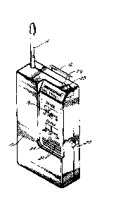
Referring to FIG. 1, a portable monitoring receiver
10 contains internal circuitry for receiving digitally-
coded FM signals from an F~I transmitter. The receiverhousing has an external mounting clip 12 so the receiver
can be worn by a parent or guardian. The exterior of the
receiver housing includes a flexible antenna 1~ directly
affixed to a printed circuit board contained in the housing.
Zo The exterior of the--receiver housing also includes a
number of alarm or status displays and controls. Some of
these are located in a recessed region on the front face
of the housing. They include an ~_D bar signal strength
indicator 16 for displaying a relative approximation of-
the distance from the receiver to the transmitter. Thedesired maximum range can be set by a slidable position
switch 18. If the range of the person being monitored
exceeds the desired range set by the switch 18, an alarm
is sounded in the receiver. If the switch is set at the
low distance setting, for example, then the receiver will
alarm when the person carrying the transmitter exceeds
that relatively low distance from the receiver. The high
switch setting allows the person to travel longer distances
from the receiver before the out-of-range alarm is activated.
The receiver housing also has a battery charging port 20,
--10--
1 a slidable on/off switch 22, and an indicator lamp 24 for
indicating when battery charging occurs. The on/off
switch 22 also can include a check position for checking
for valid signal transmission and for determining whether
a constant audible update beep tone is received. The
receiver housing also can include other alarms and indicator
lamps. These can include LED indicator lamps 26 and 28,
respectively, for visually indicating detected emergency
conditions (described below) in conjunction with sounding
corresponding audible alarms. The receiver alarm circuitry
is set to produce the same visual alarms via flashing the
LED displays 26 or 28 independently of the particular
alarm being ~etected. Alternatively, separate LED displays
can be activated to indicate the particular emergency
being detected. The audible signals produced by the
receiver are detected through sound holes 29. The various
arrangements of the emergency and status condition warning
lamps and displays and the control switches sho-~m in FIG.
1 are illustrated as an example only, since other variations
of this arrangement can be used without departing from the
scope of the invention.
FIGS. 2 through ~ illustrate a portzble transmitter
housing 30 containing circuitry fo~ a digitally-coded FM
transmitter. The transmit'er can be worn by a child whose
whereabouts are being monitored- The front face of the
housing includes a push button 32 for serving as a manual
panic switch or call button to send an alarm to the receiver
to alert the guardian when the child believes his or her
safety is in danger. The receiver carried by the guardian
sounds an alarm when the panic button 32 is activated.
The front face of the transmitter also can include an
indicator lamp 34 which blinks at a 4 hz rate to indicate
transmission, alarm and status signaling.
As shown best in FIG. 3, the transmitter housing has
a rear mounting clip 36 for use in attaching the transmitter
~ za711.4
--11--
1 to the child's clothing. The clip 36 can serve as a
safety clip to activate a power switch conr.ected to the
transmitter circuitry for activating the trans~itter and
for sending a signal to the receiver to indicate when the
transmitter has been tampered with or is re~oved from the
child's clothing. The safety clip is mounted to the
housing by a spring-biased roll pin 35. When the safety
~cl-ip--nor~ally a't~ac~hès`thè''hous~ng t`o the child's clothing,
the power switch remains closed. The power switch opens
when the safety clip is momentarily opened or removed from
the clothing, thereby activating an anti-tamper alarm,
described in more detail below.
The bottom face of the transmitter housing can include
a pair of phone jacks 38 electrically connected to circuitry
within the transmitter housing for producing signals sent
to the receiver to monitor various conditions such as
immersion and wetness, and breathing. If the transmitter
senses wetness, or is immersed in water, jr the subject stops
breathing, or if any-of the external sensors-or`'probes is
unplugged~during'ùse,'àn alarm sounds at the receiver.
The transmit'er and receiver functions are understood
best by referring to the functional block diagrams of
~/ FIGS. 5 and 6~ Briefly, the tr~nsmitter serves as a
remote transducer worn by the child being monitored. An-
emergency warble alarm sounds at the portable monitoringreceiver if the child exceeds a pre-set distance range,
falls into water, if transmitter removal is attempted, if
the breathing sensor indicates that breathing has stopped,
or if the transmitter's call button is pushed. A telephone
ringing sound can b`e prbduced at `the'transmitter'if the
call button is actuated. Other status alarms are activated
if the~wetness sensor probe or pad become wet, or if
either the transmitter or receiver battery power becomes
low. A sound similar to dripping water can be produced if
the wetness sensor is activated. The receiver is constantly
~37~4
-12-
1 listening for multiple digitally-coded F;l sig~als from the
transmitter at pre-set transmission intervals of about 10
seconds. If a required signal is not received within any
transmission interval, such as if a pre-set range is
exceeded, an alarm at the receiver is i~ediately activated.
TheFMcarrierandmultiple-codedbursts~itheachtr2nsmission
interval reduce the probability of false alarms. The
transmitter has a removable battery in a separate adapter
(not sho~m) for permitting continuous operation of the
transmitter. The transmitter and receiver cireuits are also
designed to permit rechargeable operation of both the
transmitter and receiver. In addition, the receiver is
capable of simultaneously monitoring two tr~nsmitters
transmitting at the same carrier frequency.
FIG. 5 schematically illustrates a digitally-coded Frl
transmitter 40 which includes an F~I hybrid trans~itter ~2,
a2700 logicgatecustomc~losdigitalintegratedcircuit(I.c.)
44, and associated analog components and a rechargeable
battery. The transmitter is desigr.ed fo- a ~axi~lu~ battery
life. A small 2.~ volt, 60 mah nicad button batter~ ~6
directly powers the custom digital I.C., a 9 vol~ converter
48, and all analog loads. The 9 vol~ converter supplies
the hybrid transmitter ~2 and a loi-vol~age battery reference
divider 50 with a regulated 9 volts- The transmitter is
activated by clipping it to clothing which closes a safety
clip switch 52 in response to contact by the external
mounting clip 36 on a transmitter s~itch plunger 37, shown
in FIG. 7. The plunger 37 can slide into a passage in the
transmitter housing for contact with a switch that closes
when the clip is in place- The plunger also can be seated
in a recess in the clip. ~hen the clip 36 is used to clip
the transmitter onto the clothing of the person wearing
the transmitter, the clothes create an interference which
prevents the plunger from entering fully into the recess in
the clip. This forces the plunger into the transmitter
~2~37~4
1 housing where it closes the suitch to indicate that the
transmitter has been pro~erly clipped onto the clothing of
the person wearing it. The safety clip switch powers all
analog loads, activates the digital I.C. via a power-down
section 54, and functions as the anti-tamper sensor. ~.hen
the transmitter,is not in use, a few microamps of cur-ent
continue to flow to the power-down section 5~ of the
digital I.C. to maintain function of the pot~er-down section.
About 60 to 120 microamps of current continue to the 9
volt converter from the battery 46. The g volt converter
is directly connected to the battery to enhance efficiency
due to the relatively large switching currents develoDed
during operation.
The radio frequency signal is produced by the FlI
hybrid,transmitter 42. The FM frequency is generated by a
surface acoustic wave (SA~) oscillator 56 for f~equency
stability. The output of the oscillator 56 is a~plified by
an amplifier 58 to produce an output of abou~ 50 to 80 mw
;into,a t4n,ed ,r~esonant printed circuit, a,n~enna 60. ~ The
^20 supply voltage from the, converter 48 is applied to the
~/ oscillator and ,amplifie~ at all times, but neither the
oscillator nor the amplifier is turned on until 0.1 ms before
a coded signal is to be transmitted.~ At that time, a pre-
enable buffer switch 62 produces an output pulse for
turning on the oscillator and amplifier before a coded
signal is transmitted. The pre-enable function permits
the oscillator to stabilize before transmitting. The
hybrid transmitter also includes a varactor modulator 66
which receives output signals from a modulator buffer
switch 68. A pulse code modulated~PCM) signal is sent to
the modulator bu,ffer,switch f,rom a Manchester encoder 70.
When the PCM signal is-sent to the modulator buffer switch,
it causes the varactor modulator to shift the 318.0 mhz
carrier frequency by 70-100 khz with each "logic 1" trans-
mitted. That is, the carrier frequency is shifted when
14
1 each "logic l" is sent out sothat the receivercan distinguishbet~Jeen a one and a zero.
The digital I.C. 44 provides all timing and logic
functions for the transmitter. A 32.768 ~hz watch c-ystal
oscillator 72 provides the time base for the digital I.C.
A burst timer 74 causes transmission of four ~Ianchester
encoded digital words in rapid succession during each
transmission interval of 10.7 seconds. Each coded word
output from the Manchester encoder 70 contains an ll-bit
factory set address code 75 from aprinted circuitprogramming
pad and a 6-bit alarm status data code 77 frcm a data
register 78. The output of the burst timer 7~. is applied
to a pulse timer 80 that produces four enabling ?ulses at
103 ms intervals during each transmission interval. fiy
changing one data bit, ~he transmit'er can ch~nge from
operating as the primary or standard transmitter to operating
as a second similar but optional FII transmi~'er producing
four enabling pulses at 110 ms intervals. T~e kurst timer
7~ instructs the four-pulse timer when to send the pulses
during each transmission interval. The burs_ timer sets
the transmission intervals at 10.7 secor.ds. The enabling
pulses from the four-pulse timer 80 are ap~lied to a 0.1
ms delay timer 82. The delay time~ then sends the time-
delayed pulses from the four-pulse timer to the ~Ianchester
encoder, delayed by 0.1 ms. At the same ti~e, the four output
pulses from the four-pulse timer 80 are applied directly
to the pre-enable buffer switch 62 for turning on the
oscillator 56 and amplifier 58 in the FiI transmitter 0.1
ms before the digitally-coded signals are received by the
oscillator.
The four coded words sent from the ~Ianchester encoder
with each burst received from the burst timer minimize
false alarms at the receiver due to interference, because
the receiver needs to receive only one of the four coded
words correctly during each transmission interval. Once a
-15-
1 valid word is received, the receiver is reset for the next
transmission interval. The coded words are also spaced
apart in time to permit maximum power transmission under
current FCC regulations. According to Part 15.122 of the
FCC Rules, transmitted power is averaged over a 100 ms
time interval. The coded words,are transmitted at minimum
intervals of 103 ms. Also, the beginning to end of each
burst must not exceed 357 ms, under present regulations.
This limits the number,of~words to four fo~ e,ach,transmission
interval. The eleventh-bit-of the factory set-code is set
to a "logic 1" on a secondary optional transmitter for
sending digitally-coded signals at the same FM carrier
frequency to the same receiver. This produces llo ms word
intervals between the coded words sent by the ~lanchester
encoder in the secondary transmitter, and thereby permits
the two transmitters to operate independently on the same
carrier frequency without mutual interference. ~ith this
arrangement, if the burst timing of the standard and
secondary,tran,smitters should- coincide or overlap, only
one of the four coded words would simultaneo~sly overl~p,
leaving three valid transmitted words per transmission
interval; or if any of the coded words happens to overlap
with one sent from the secondary t~ans~it'er, or from any
other independent transmitter, other valid words can be
received during the set transmission interval. As a
result, false alarms are essentially avoided because the
system generates the re,d,undant coded worc,s for each trans-
mission interval, and only one valid word needs to be
transmitted to the receiver to reset the receiver for the
next transmission interval. By sending four coded words
over a relatively lon~-:time interval with interdigitation
due to their difference in time period, the probability is
that at least one coded word will be passed to the receiver
from each transmitter without interference. If at least
one of the coded words is not received by the receiver during
1 any transmission interval, then an emergency condition is
immediately detected~at the receiver, and an alarm at the
receiver is activated. The duration of each coded word is
limited to about 2 ms to maintain signal integrity while
permitting boosting signal power due to FCC averaging over
a 100-ms word interval.
As mentioned previously, the transmit~er generates both
emergency alarms and status information. ~11 emer~ency
alarms (except out-of-range) immediately trig~er the burst
timer 74 out of sequence to send a coded burst to the
transmitter circuitry, followed by no kurs's for 22.5
seconds, or until the alarm condition is cor-ec_ed.
22.5 second delay timer 8~ controls the ti.me delay ollo:ling
a triggered emergency alarm. The burst ti.~- r.o~~ally
sends its timing pulses to the l~ancheste- enc^~er each
10.7 seconds, but when the burst timer is trigge~ed by an
alarm signal, it immediately sends a timing pulse to the
Manchester encoder to send the emergency alar~ to the
receiver. After the burst timer is triggered by the
emergency condition, the burst timer is disz~led fo- the
next 22.5 second time interval to prevent ot;-e~ pulses
from being sent by the burst timer during ~he emergency
alarm phase. The purpose is to set--a signalir.g priority.
If emergencies such as immersion, tampering sensed hy the
anti-tamper switch 36, or breathing failure are detected~
an emergency alarm is immediately generated; andtransmission
of other secondary information, such as call-buttonsignaling
or wetness detection are overridden. Triggering inputS to
the burst timer are controlled through an OR gate 96. The
disable inputs to the burst timer are controlled through
an OR gate 97. During the "no burst" period, an LED 86
flashes at a 4 hz rate controlled by a 4 hz oscillator 88
coupled to the LED display through an OR gate 90 and
buffer switch 92. The burst timer is disabled at the OR
35 gate 97 to prevent any other coded signals from being sent ~-
7114
1 out once an emergency alarm has been tri~gered. The
purpose is to prevent sending ot~.er digitally codel bursts
which could be interfered with e~ternally and which might
erroneously inform the receiver that the emergency was
later corrected and that the transmitted al2~m signal had
simply been a false alar~. That is, by stopping transmission
fo these further signals, interference from such signals
is prevented, where such signals possibly could reset the
alarm and make the alarm cease, while ma~ing the user
think that the alarm that sounded ~as a false alarm, ~hen
it was not. - -
The anti-tamper alarm system sends an alarm signal to
the receiver when tampering with the transmitter is detected.
The output from the safety clip switch 52 is coupled to an
input of an AND gate 94. The output of the safety clip
switch also is coupled to the burst timer 74 through the OR
gate96 whichcontrolsthetriggering inputtothebu~sttimer.
When the safety clip s~7itch:is closed, the po~er-down
section 54 is disabled and the digital IC is-powered up,
;zo with all registers and timers being initialized by the
system reset 98, which is coupled to the output of the
safety clip switch. ~7ithin a few milliseconds, a coded
signal is transmitted for indicatiRg that the transmitter
has been properly clipped to the person wearing it. An
8-sec./4-sec. delay timer 100 has an output coupled to the
input of the AND gate 94. The output from the AND gate 94
is coupled to the 22.S second delay ti~er 84- The AND gate
94 produces a "logic 1" when the inputs from the safety
clip switch and the 8-sec./4-sec- delay timer are in a
"logic 1" state. The 8-sec. output from the delay timer 100
serves as a disable signal applied as an input to the AND
gate 94. When the 8-sec./4-sec. delay timer starts, it
disables the 22.5-sec. delay timer 84- The output from
the 22.5-sec. delay timer is coupled to the data register
78. The delay timer output also is connected to the OR
~37114
-18-
1 gate 96 that triggers an in~ut to the burst timer and to the
disable input of the burst timer through the OR gate 97.
Once the 22.5 second delay timer has been disabled the
safety switch clip can be clipped and unclipped at ~
for the first 8 seconds without activating the 22.5 second
anti-tamper alarm. The 4 second time delay output from the
delay timer 100 is coupled to an input of the OR gate 90
and then to the LED display 86. During the first 4 seconds
of the 8 second period after the safety chip is closed
the LED86stays ontoindicate reclipping isstill permissible
without activating the 22.5 second anti-tamper alarm. If
the safety clip s~itch is opened after the 8 second delay
period the delay timer 100 times out and enables the AND
gate 94 and the burst timer 7~ is triggered to transmit an
immediate anti-tamper alarm signal to the receiver. The
anti-tamper alarm can be activated even if the anti-tamper
clip switch is opened for a fe~ milliseconds. The anti-
tamper alarm signal is followed by no signal transmission
to the receiver for the 22.5 second delay time interval
even if the transmitter is immediately recli~ed. If the
transmitter is immediately reclipped no--al transmissiOn
will resume within 22.5 seconds. If the tr2nsmitter is
not reclipped, then all transmis-sions cease and the
pouer-down section 54 is triggered to power down the I.C. u~l.
The breathing alarm system produces an alarm signal
if sensed breathing rate is too fast or too slow. The
breathing alarm is controlled by a capacitive sensor (not
shown) coupled to a breathing monitor jack 102. The
sensor detects abdominal motion and thereby provides
breathing information to the breathing alarm system. The
breathing sensor can be formed by two small plates about
one inch square attached to a semi-rigid plastic substrate
and coated with a thin layer of plastic- The plates are
held in contact with the abdominal area by a strap around
35 the body. The dielectri~ constant of water is about 80 times ~<
371~4
--19--
1 that of air, and since the plates make imperfec~ contact with
the body, inhaling increases capacitance, and exhaling
causes a reduction in capacitance. No movement causes no
change in capacitance. ~hen the breathing monitor plug is
inserted into the input jack 102, the breathing monitor is
enabled. The 32.768 khz time base serves as the carrier
for detecting capacitance changes. The time base signal
is connected to one of the capacitor plates, and the other
capacitor plate functions as~an output plate.~ During use,
the magnitude of the 32.768 khz signal at the output plate
varies directly with breathing. The output from the
breathing monitor jack 102 is coupled to a lo~t-pass filter
104 which strips the 32.768 khz car-ier fro~ the signal,
leaving a low-level, time-varying signal. This signal is
amplified by a virtual ground input amplifier 106 with level
changes detected by a virtual ground input comparator 108.
The output from the comparator 108 is cou~led to the L~D
display 86 through the OR gate 90 and buffer switch 92.
Bec~use of a small: amount of hysteresls built into the
comparator,~ the transmitter LED flic~:ers with a rate and
duration proportional to the rate and durationofeach inhaled
breath. This confirms that breath`ng is occurring and
that the monitor is properly attac~ed to the person being
monitored. ~`~
The breathing monitor alarm is produced by coupling
the output from the comparator to a 5 to 20 second time
interval timer 110. The output of the timer is coupled to
the trigger and disable inputs of the burst timer 74 through
the OR gates 96 and 97, respectively- If, during any 20
second period, there are either no pulses or more than 40
pulses n$rom the ~cQmparat-or 10~ the timer~ll0 is not
reset. This produces a breathing monitoralarmby immediately
allowing the burst timer to-send a-breathing monitor fault
code to the receiver, followed by no transmissions to the
receiver and a continued alarm at the receiver until
. , , - . .
:
;
lZ~ 4
-20-
1 either breathing resumes or the breathing monitor senso-
is unplugged from the jac~ 102. The L~D ~6 flashes at a 4
hz rate during the alarm condition.
The immersion alarm is activated when the transmi~.er
is immersed in water. Immersion of the trans~it~er is
sensed by the exposed cylindrical conductors of two adjacen.
subminiature phone jacks 102 and 112 at the bottom of the
transmitter housing. ~ne of the conduc'ors is at ground
potential. The other conductor is pulled to a high potential
by a large value resistance and is common to the input of
an immersion comparator 114. When water bridges the
conductors, the immersion comparator input drops below a
comparator reference voltage for activating ~he immersion
alarm. The output from the immersion comparator is coupled
to the data register 78 and to the triggering and disabling
inputs of the burst timer through the OR gates 96 and 97.
The burst timer is i~mediately triggered when the output
from the comparator is produced to send an immersion fault
code to the receiver. The LED 8~ also flashes at a 4 hz
rate. All further transmissions thereby cease until the
transmitter is properly dried and resto~ed ~o operation.
The call alarm or panic alert operates as follows.
The call button 32 on the transmit'er is coupled to the
data register 78 and to the burst timer 74 through a 22.5
second latch timer 116. When the transmitter call button
is momentarily actuated, the 22.5 second timer is latched,
which triggers the burst timer to send an immediate call
alarm fault code to the receiver, followed by no further
signal transmissions for 22.5 seconds. During the 22.5
second time interval, the LED 86 flashes at the 4-hz rate.
At the end of the that period, the call condition resets,
and normal transmitter function resumes.
The monitoring system detects diaper wetness and bed
wetness. Diaper wetness is sensed by an external two-
conductor probe (not shown), and bed wetness is sensed by
~ ~7~4
-21-
1 an external two-conductor screen (not shown). The output
detected by either wetness sensor is sho~n cou~led to t~e
jack 112 on the transmitter housing, although these detectors
also could be coupled to other separate input jac~s on the
transmitter housing. The sensed wetness information is
coupled to a wetness comparator 118. Conductive fluid or
water at the sensor pulls the wetness comparator input
below a comparator reference input to activate the wetness
alarm.~The output from the wetness comparator is -coupled
to the data register 78, but not to the burst timer because
the wetness alarm is not an emergency condition. The
wetness fault code is instead transmitted to the receiver
with each burst until the wetness condition is corrected
or the sensor is removed from the jack. Other sensors may
also plug into the wetness jack, permitting sensing of
light, heat, pressure, force, etc.
The voltage output from the 2.5 volt nicad battery is
constantly monitored by a low-battery voltage co~parator
120. The-battery voltage is compared with a-factory-set
reference resistor divider voltage having a regulated 9 volts
from the 9 volt converter 48 as its source. ~ihen the battery
voltage falls below the reference divider factory-set
voltage, the low-battery comparator causes a lo-~t-battery
voltage fault code to be transmitted with each burst until
the battery is changed or recharged.
The FM receiver is understood best by referring to
the functional block diagram of FIG. 6. The receiver
includes a power supply 122, a radio frequency section
124, an intermediate frequency (I.F.) digital integrated
circuit (I.C.) 126, a 2700 gate CMOS custom digita I.C.
128, a signal strength meter 129,.-a-power switch~.l30,- and
miscellaneous ana~og components- The receiver also has a
range switch 131, the signal strength bar indicator 16
(see FIG. 1), red and green transmitter monitor LEDs 132
~2~7114
-~2-
1 and 134 (shown at 26 and 28 in FIG. 1), a c~.arge status
LED 136 (shown at 2~ in FIG. 1), and an audible alar~ 13~.
Thepowersupplyprovides2.5voltstoo~eratethe digi~al
I.C. and analog loads. It also provides 8.0 vol.s for
operating the radio frequency section, the I.F. digital I.C.,
and a low-battery reference divider 1~0. The main co-~po~ent
of the power supply is a pair of series cylindrical nicad
cells 142 providing 2.5 volts at 500 mah. A 6 vac household
current battery charger 144 permits simultaneous charging
of the battery while operating the receiver. An optional
DC adapter can permit charging or operating the receiver
from 12 vdc automotive current. An optional sol~r panel
can permit charging or operating the receiver directly
from sunlight. A single adaoter can allo.r an~ of the
chargers to charge up to two transmitter batteries while
charging the receiver battery. A resistor bet~een the
battery charger and the receiver bat'ery pac~ 1~2 drops
excess voltage and limits the charge current to t~.e bat'ery
pack. The charge status LED 136 is illuminated while the
battery pack is being charged. The trans~it_er battery
charger adapter is designed the sa~.e way. ~7hen not in
use, and with the power switch in the of r position, no
current flows from the battery pack to the loads. When
the power control switch is moved to the check or on
positions, power is provided to all loads. ~lhen in the
check position, an audible beep is emitted each time a
signal is received (approximately every ten seconds), as
well as emitting a flash from the appropriate transmitter
monitor LED. ~hen in the on position, only the LED flashes.
The receiver system is a superheterodyne receiver in
which the frequency of incoming radio signals is converted
to an intermediate frequency by mixing with a locally
generated signal. The radio frequency section 124 of the
receiver provides a down conversion function by converting
35 the 318.0 mhz FM carrier signal to a 10.7 mhz intermediate
128~14
--23--
frequency (I.F.) signal. The 318 mhz signal is received
through a 5-inch long antenna 146, which is impedance-
matched to 50 ohms with a loading coil in an antenna
matching circuit 148. The signal is then coupled to a
pre-amplifier 150. The essential signal-to-noise ratio is
determined by the gain and noise contribution of the RF
pre-amplifier~ The selected pre-amplifier transistor is
based on the RF performance requirements and a demanding
current consumption constraint necessary in order to have
a product with substantial operational battery life. The
output from the pre-amplifier is coupled to a -7 ds mixer,
which is a balanced Schottky barrier diode ring type
mixer. This mixer is used because of the good performance
with variable mismatches experienced in production and
because of high immunity to interference. The mixer
improves the product operating reliability. The Schottky
diode is characterized by nanosecond switching speed, but
relatively low voltage. A local oscillator 154 produces a
307.3 mhz signal of sufficient power level to bias the
mixer. Oscillation frequency is determined by a surface
acoustic wave ~SAW) device designed into a transistor
circuit where the DC to RF efficiency is of prime
importance to conserve battery life. The output from the
mixer 152 is a 10.7 mhæ intermediate frequencyl which is
then filtered by a 400 khæ ceramic filter 156 to preserve
the difference signal (318.0 mhz - 307.3 mhz = 10.7 mhz).
The output from the filter is then amplified by a high-
gain, super low current-consuming transistor stage of a 22
dB intermediate frequency pre-amplifier 158. The entire
radio frequency section 124 is designed to operate on very
low current ~about 5 ma).
The I.F. digital I.C. stage 126 further processes the
10.7 mhz output from the radio frequency section 124. The
I.F. stage 126 amplifies, filters, and detects the FM
;~ signal, 35 as well as providing a signal strength output
for operating
~ ~37~4
-2~-
1 a signal strength display. The I.F. digital I.C. is soeci-
fically selected for its lo~ current consumption of about
2.0 ma to conserve battery life as well as its wide-band
capability. Thesignal intotheI.F. digitalI.C. isamplified
by a 40 ds amplifier 160. The output impedance of tne
amplifier 160 forms a resistive divider with single range
switch resistors to ground for limiting range on lo~l and
medium range switch settings of the range switch 131.
Range can be set in tens of feet on low range and hundreds
of feet on high range, which has no resistor to ground. A
second 10.7 mhz, 400 khz band width ceramic filter 162 is
coupled between the 40 dB amplifier 160 and a 50 dB limiter
amplifier 164 for further improving the signal-to-noise
ratio. The 50 dB limiter amplifier further boosts signal
level up to 50 dB as required. The signal fro~ the limiter
amplifier 164 is detected by a quad-ature detector 166 to
remove the modulation from the 10.7 mhz F-l intermediate
frequency carrier signal. Thellanchester data code detected
by the receiver is originally in the form of square waves
on a DC level. A virtual ground bufCer amplifier 168
amplifies the square wave component to provide a lo-
~impedance source to drive the digital I.C. This output
from the amplifier 168 represents the digitally coded
receiver input signal with all emergency alarm status
condition data from the transmitter. This signal is
decoded and further processed by the receiver I.C.' ~
Signals from both the 40 dB amplifier and the 50 dB
limiter amplifier are independently rectified by a full-
wave rectifier 170 and summed in a voltage-to-current
converter 172 to produce an output current logarithmically
proportional to signal strength- This output is used to
operate the relative signal strength meter 129.
A high-impedance, current-to-voltage converter 174
changes the relative siynal strength current of the I.F.
digital I.C. to a voltage output amplified and changed to
~Z~7~1at
-2~
1 a low-impedance source by a buffer am~lifier 176. The
output from the buffer amplifier is filtered by a low-pass
filter 178 and then fed to a s-e1ement bar L~D driver for
a 5-LED signal strength indicator 182. The output of the
amplifier is low-pass filtered so that each of the four
2 MS digital words will cause much of the meter's bar to
remain illuminated until the next 2 ~IS word arrives. The
result is a bar which remains illuminated at a length
proportional to relative signal strength with the most
significant LED flickering. The 5-element bar LED driver
converts the signal level into five discrete steps and
drivestheS-LEDbarsignal strength indicator. ~pproximately
every ten seconds, the signal streng_h indicator flashes
on with the received signal giving a relative approximation
of distance to the transmitter.
The digital I.C. performs all timing, logic, alarm
generation, and signal decoding for the receiver. It uses
a 32.768 khz watch crystal 18~ as its time base. The
output signal from the intermediate frequency I.C. (i.e.
;20 from thè amplifier 160)- provides the in~ut signal 186 to
the digital I.C. 128. This input signal is processed by a
~Sanc~ester decoder l88 by comparing a 10-bit, factory set
address code 190 with the incoming ll-bit address code.
If the first ten bits of the address code cor~elate with the
receiver code, a valid output signal 189 is generated by
the ~Ianchester decoder. Valid output signals mean that
coded information in the decoder matches coded information
sent from the transmitter. :For instance, as long as any
of the four coded words produced during each transmission
interval is received, a valid output is generated. The
~eleventh bit determines--~Lhether the ~alid signal is from
the standard transmitter or a secondary transmitter. The
remainder of the signal includes alarm fault data, which
is latched into a data register 192 for the standard
transmitter or an optional data register 194 for the
7114
-26-
optional or secondary transmitter. The valid out-ut
signal from the ~Ianchester dec~er is coupled to a flrst
AND gate 196 corresponding to the standard transmitter and
to a second AND gate 198 corresponding to the optional
5 transmitter. The standard output signal from the i!anchester
decoder is sent to an 8 second timer 200 and to a standard
transmitter ENABLE latch 202, the output of which is
applied to an 11.1 second standard transmitter timer 204.
This output produces an enabling signal to the 11.1 second
10 timer 204. The output from the first AND gate 196 is coupled
as a RESET signal to the 11.1 second timer. The optional
transmitter output from the Manchester decoder is similarly
coupled to an 8 second timer 206 and an optional tr~nsmitter
ENABLE latch 208 to provide an enabling in~ut to an 11.1
15 second optional transmitter timer 210. The valid out~ut
signal from the Manchester decoder is cou~led with the
optional transmitter output through the second A~iD gate
198 to the optional transmitter timer 210.
I~hen a transmitter is first activated, it immediately
20 sends a burst. If the burst is from the standard transmitter,
it starts the 8 second timer and causes the red LED 132 to
glow during the 8 second period to indicate that the
transmitter clip may still be repositioned without activating
the anti-tamper alarm. The 8-second timer is connected to
25 the LED 132 through an OR gate 211. At the end of the 8
second ~eriod, the standard transmitter ENABLE latch is
triggered, which causes the standard transmitter timer to
start. If no valid signal is received before 11.1 seconds
elapses (e.g., the transmitter moves beyond the preset
30 range), a warble oscillator 212 begins and continues until
a valid reset signal is received. The optional transmitter
signal is detected and monitored in the same manner as the
standard transmitter. The 8-second timer is connected to
the optional LED 134 through an OR gate 213. The LED
35 signals indicate the time period during which reclipping
~2~7~4
-27-
1 is permissible without causing transmission of an alarm
signal. The outputs from thestandard and optional ll.lsecond
timers are coupled to the warble oscillator 212 t~._ough an
OR gate 214. The output from the optional transmit.er
also passes through the OR gate 215. The out?ut fro~ the
OR gate 214 is coupled to the red L~3 132 ar.d the green
LED 134 through a 4 hz oscillator 216. If one of t-.~o
previously-functioning transmitters is switched off ~hile
the receiver is still operating, the warble alar~ 212 will
sound until the receiver power switch is momentarily
switched off. This causes the power-up system reset 218
to unlatch both ENABLE latches and ter~inate the alar~.
If neither of the two transmitters is functioning when the
receiver power switch is turned on, the receiver will
remain silent until a valid signal is first received.
Each time a valid signal is received and indicated by
signal 189, a beep timer 191 generates a 25 ms beeping
tone at the audible alarm 138.
The data registers 192 and 19~ store alarm fault data
received from the transmitter. For exa~ple, ~-hen a valid
address signal from a standard transmitter is decoded, the
first AND gate 196 strobes high to store the data bits of
the Manchester decoder 188 in the -standard data register
192. Each of the six data bits conveys alarm status
information. In addition, loss of signal or out-of-range
alarm is given at the output of the transmitter timer.
Receiverlowbattery is determinedby the receiver low-battery
comparator 280 external to the digital I.C. The alarms are
separated into three categories listed in descending order
of priority as follows: emergency, call, and status
alarms. Emergency alarms include out-of-ran~e, immersionl
anti-tampering, and breathing monitor- There is only one
call alarm. Status alarms include transmitter low battery,
receiver low battery, and wetness detection.
~2~37~14
~28-
1 All emergency alarms are combined at the O~ gate 214
which activates the warble oscillator 212 and disables the
call and status alarms at ~ND gates 220, 222, and 224,
respectively. The warble oscillator signal corbines with
a 3 khz oscillator signal from an oscillator 226 at an ~ND
gate 228 to operate the audible alarm at a low level,
through a low-level buffer 229. Simultaneously, the
output from an OR gate 230 triggers a ~ second timer 232,
which permits four seconds to elapse before switching to
an AND gate Z34 to pass the warble oscillator signal
through an OR gate 236 to combine at an AND gate 238 to
operate the audible alarm at high volume. The audible
alarm on high volume is controlled through a high-volume
buffer 239. During the audible alar~, the LED 132 is
lS flashed by the 4 hz oscillator 216, which is activated by
the OR gate 240. The output of the oscillator passes
through an OR gate 242 and is passed through either or
both of the AND gates 244 and 246, depending upon which of
the standard and/or optional transmitters is at fault as
sensed at the OR gates 248 and 2So, respectively. If, for
example, the standard transmitter is in fault, either (SA)
at the output of the OR gate 252 or (S~') at the output of
the standard transmitter timer 204-is high. This causes
only the red LED 132 to flash at the 4 hz rate. The green
LED 134 is activated in a similar manner to produce an
emergency alarm for an optional transmitter.
The receiver constantly monitors range information
from the multiple coded bursts sent by the transmitter
during each 10.7 second transmission interval. Range is
determined as a function of the signal strength of the signal
received by the receiver. out-of-range is measured by
controlling the sensitivity of the receiver. The range
s~itch 131 is used to adjust the sensitivity of the receiver.
If a low range is desired, the range switch on the low
setting reduces the receiver sensitivity, i.e., its ability
~ ~37~4
-29-
1 to receive signals from the trans~itter. Therefo-e, t~.e
person wearing the transmitter can e~ceed a sho-ter ou'-
of-range distance before the reduced sensitivity will
cause the signal to drop out and produce an out-of-ranse
alarm. The out-of-range condition produces a loss of
signal at the output from the 50 dB amp~ifier 16~
also causes the output from the current-to-vol~age converter
~to drop out so that the -signal strength meter will indicate
an out-of-range condition. Loss of signal is detec~ed at
the output 186 from the amplifier 168. None of the signals
from the transmitter will be received during the 10.7
second transmission interval when loss of sig~al occurs.
In this event, AND gate 196 does not reset the 11.1 second
timer 204 and the timer times out and O~ gate 2~0 then
activates the warble oscillator 212 to indicate the out--of-
range condition. The magnitude of the signals sent to the
receiver is used to detect out-of-range. Although the
signals sent to the receiver are digitally ccded, the
digital codes (for transmission of address and data infor-
mation) are not used for transmitting range information.Out-of-range information is transmitted only through the
signal strength of the digitally ccded signals, and the
range switch adjusts receiver sensitivity to the incoming
signals in order to control the level at which the out-of-
range alarm is activated.
This technique for detecting out-of-range condition
through the use of receiver sensitivity adjustments is
important in reducing the overall cost of the receiver.
Signal sensitivity is controlled by the voltage divider
which divides the incoming signal so that the output level
of the signal can be lower than its input level to use the
lower signal level to reduce receiver sensitivity. This
technique requires only a few resistors and -a standard
switch to accomplish its purpose at a modest cost.
~LZ~71~
-30-
1 A call oscillator is generated from 20 pps of 2~ ms,
each being switched on and off at a 1 h~ rate. The call alar~
sound resembles a telephone ring. ~ call ti~er 2,3 is
activated by call fault data, eit~.er fro~ the star.~rd
data register 192, or fro~ the optional data register 19~.
Either signal passes through an OR gate 25~ havi~ an
outputwhichdisablesthebeep,wetness,andlow-batteryala~s
via an invertor 256 at the AND gates 222 and 22~. The OR
gate 254 also enables the 4 hz oscillator via the OR gate
240, which flashes the LED's 132 or 134 via the OR gate
242, depending upon whether the optional or stand~rd
transmitter, or both, are registering a call fault. Ic
the standard transmitter is at fault, the out~ut (SC)
combines at the AND gate 2~4, via the OR gate 2~8, ~lit~ the
output from the OR gate 242 to flash the red LED. ~ call
from the optional transmitter flashes the green LED 13~ in
a similar fashion. The c211 timer generates the call
alarm, which passes through the AND gate 220 and the OR
gate 230 to combine with the 3 khz signal at the ~iD gate
228 to operate the alarm at the low level. Si~ultaneously,
the signal output at the OR gate 230 triggers the 4 second
timer 232, ~hich activates the high-volume alarm via the
AND gate 234, the OR gate 236, and-the AND gate 238 after
the 4 second delay has elapsed.
The wetness alarm is a 25 ms pulse at two second
intervals generated by a wetness timer 260. This timer is
activated by wetness data fault codes, either from the
standard or optional transmitters via the OR gate 262.
The output from the wetness timer operates the high-volume
30 alarm via an OR gate 264, the AND gate 224, the OR gate
236, and the AND gate 238. The red LED 132 is flashed
with each pulse when an OR gate 266 is activated, which
drives the OR gate 248 via an AND 268 simultaneously with
the OR gate 264 driving the AND gate 224 and the OR gate
35 242. AND gates 222 and 224 disable the wetness flashing
"': . , :
' ' -
~, '
~ .
14
1 when a call or emergency alarm occurs. The green LED 134
is flashed in a similar way by an OR gate 270 via an AND
gate 272 and the OR gate 250 in conjunction ~ith the OR
gate 264, the AND gate 22~, and the OR gate 2~2.
The transmitter low-battery alar~ comprises a 25 ms
pulse followed by a second 25 ms pulse within a 0.5 second
interval. The pulses are generated at a transmitter low-
battery timer 273 with each ten second transmission trigger
received from the OR gate 274 when enabled by an QR gate
276. The LEDs are discriminately driven, and high-volume
alarm is functioned using the same gates and in the same
manner as in the wetness alarm.
The receiver low-battery alarm is generated within a
receiver low-battery timer 278 with each ten second trigger
lS from the OR gate 274 when enabled by a receiver low-battery
comparator 280. The alarm is t~o 25 ms pulses separated
by 62 ms. No LEDs are flashed, but the audible alarm is
activated in the same way and with the same gates as the
wetness.and 1QW transmitter battery alarm. It--is possible
for all three--status al-arms to occur si~ultaneously.
-The following summarizes certain characteristics of
the receiver circuitry, the implementation of which will
- be apparent to one skilled in the art.
The 10 dB gain RF amplifier consumes less than one
milliamp of current and has a 4 dB noise level, with the
following selected transistor device electrical character-
istics:
collector-emitter breakdown voltage S volts DC (Min.)
collector-base breakdown voltage 10 volts DC (Min.)
emitter-base breakdown voltage 2 volts DC (Min.)
30 collector cutoff current (Max.-) - 50 nanoamps DC
current gain-bandwidth product 3 GHZ typical
collector-base capacitance (Max.) 0.5 picofarads
noise figure ~ ~ -4 dB typical
The I.F. preamplifier consumes less thah` onë miiliamp
of current and has a 22 dB gain, with the following selected
S transistor device characteristl~s:
.' , - , .
~ .
12~7114
-32-
l collector-emitter brea~dotm voltage 5 volts DC (;lin.)
collector-base brea~down voltage lO volts DC (rIin.)
emitter-base breakdo~m voltage 2 vol's DC (rlln. )
collector cutoff current (2Iax.) 50 nanoa~.. ps DC
current gain-bandwidth product 3 G-.-Z ty~ical
collector-base capacitance (IIax.) 0.5 picorarads
5 noise figure ~ d3 t~pical
The intermediate frequency I.C. consu~es less than
2.5 milliamps of current and has a 90 dB gain, with the
following selected transistor device characteristics:
power supply voltage 4.5 volts DC (rlIN. )
lO field strength range 90 dB typical
field strength accuracy +/- l.5 dB typical
I.F. input impedance lSoO OHrlS (r~Ii~.)
quadrature output impedance 50,000 oHr~s (rIIN.)
~<