Note : Les descriptions sont présentées dans la langue officielle dans laquelle elles ont été soumises.
73~'3
Back~round of the Invention
This invention relates to an apparatus and method
for purifying gases and, in particular, to an apparatus and
method for purifying hydrogen gas.
Many present day industries utilize in their
manufacturing processes hydrogen of over 99% purity.
Chemical producers, food manufacturers, and electronics
manufacturers, to name a few, require pure hydrogen for
various purposes.
Most industrial processes for producing hydrogen
provide the hydrogen in less than 75% concentration.
Catalytic steam reforming of natural ga3 or light
hydrocarbons, partial oxidation of heavy hydrocarbon stock
and coal gasification all produce dilute hydrogen. Also,
dilute hydrogen is often available as a by-product in
several chemical industries.
To obtain pure hydrogen, small scale users
generally employ a co~tly electrolytic process or purchase
merchant hydrogen. Large scale users, on the other hand,
use state-of-the-art purification techniques such as
scrubbing, cryogenic separation, pres ure-swing adsorption,
or membrane diffusion ~eparators,
In the conventional electrolytic type of processlng,
hydrogen oontained in water is converted to gaseous
hydrogen by oxidizing water in an electrochemical cell. In
another electrolytic process, the hydrogen contained in a
gaseous mixture is transformed into ionic form in contact
with a palladium membrane. The ionic hydrogen at the
surface o the membrane is converted to atomic hydrogen and
the atomic hydrogen then passes through the membrane. At
the output end, the atomic hydrogen is converted to
molecular hydrogen and thereby pure hydrogen is produced.
The above method~ however, is disadvantageous in
. ' ' ` ~ . ~
.~ :
~l2~73~'3
- 2 _
tha~ it is ~ensitive to temperature and impurities such as
~ulfur and hydrocarbon compounds. Also, the pressur~ o th~
hydrogen on the input side of the membrane must always be
higher than that on the output side. The palladium based
membranes are also prone to loss of stability after repeated
cycles of adsorption and desorption~
U.S. Patent 3,446,674 to Giner discloses an
electrochemical converter which likewise relies on atomic
hydrogen being generated and being passed through a
palladium membrane. More specifically, Giner discloses a
converter which employs an anode which is provided with a
dehydrogenation catalyst~ The cathode member is a palladium
membrane permeable to hydrogen. An electrolyte is disposed
between the anode and cathode and a pow~r supply is
connected to the anode and cathode to complete the circuit.
In operation of this converter, a gaseous mixture
such as hydrocarbon and steam is passled into contact with
the anode and undergoes a reaction under the influence of
the dehydrogenation catalyst and current to produce hydrogen
- 20 iong and carbon dioxide. The hydrogen ions p35S from the
catalyst through ~he electrolyte to the cathode palladium
membrane where they accept electron~ to form atomic
hydrogen~ The atomic hydroge~ then permeates through the
membrane and in the manifold at the outlet side of the
membrane is formed into molecular hydroge~ which i8 now
substantially pure.
Giner also discloses that the anode of his
converter may be formed by coating a conductive metal creen
with a suitable dehydrogenation catalyst and treating the
screen with a hydrophobic matérial. In this regard, Giner
states that other structures may be employed for fabricating
the anode, including metal elements inherently permeable to
gases such as the porous electrode structure disclosed in
Bacon U.S0 Patent No. 2,928,783 and that the metal may be
3~Z8~323
inherently catalytic such as palladium and platinum.
The converter described by Giner relie~ upon the
permeation of atomic hydrogen through a palladium cathode
membrane in order to effect hydrogen purification. This
makes the cell sensitive to temperature variations and
impurity levels, as well ae requiring a large differential
pressure across the palladium membrane for operation.
Furthermore, Giner acknowledges that part of the hydrogen
will be evolved on the cathode face of the palladium
membrane. This will result in hydrogen 1088 and ~eal
leaks. Also, the palladium membrane has a high hydrogen
over voltage which makes it prone to large power
consumption. Finally, the stability of the membrane in an
acid media and under the requir~d operating temperature and
repeated cycling is also questionable. The Giner converter
thus i~ di~advantageous in a number of respects.
It is therefore an object of the present invention
to provide an apparatu~ and method for purifying hydrogen
which do not suffer from the above disadvantages.
It is a further object of the pre~ent invention to
provide a hydrogen purification apparatu~ and m~thod which
can provide an output gas pressure which is approximately
equal to or greater than the input gas pre~sure.
It i9 yet a further object of the present invention
~o provide a hydrogen purification apparatus and method
which are highly stable and which provide increased output
capacity.
. .. .
- . ...
~ : ' ' ' . .' :
.
. .
~' ' , '
~2~37323
-- 4 --
Summary of the Invent_on
In accordance with the principles of the present
invention, the above and other objectives are realized
through the ~se of a hydrogen purification apparatus
comprising an assembly which includess an anode gas
diffusion electrode, a cathode gas diffusion electrode,
first and second gas passages adjacent the anode and cathode
electrodes, respectively; an acid electrolyte sandwiched
between the electrodes; and means for applying a voltage
across the electrodes.
As used herein, the term "gas diffusion electrode"
means an alectrode having macroscopic pores sufficient to
permit the passage of molecular hydrog~. Electrodes
meeting this requirement have pores approximately equal to
or greater than one micron.
With the above configuration for the purification
apparatus, impure or dilute hydrogen supplied to the first
gas passage of the assembly is converted via the anode gas
diffusion electrode, the electrolyte and the cathode gas
diffusion electrode to molecular hydrogen which passes
. . ~
through the cathode electrode and into the second gas
passage as substantially pure hydrogen. Since the hydrogen
passes through the cathode electrode in molecular form, ~he
disadvantages attendant passage in atomic form experienced
by the Giner converter are substantially eliminated.
Furthermore, since the gas diffusion electrodes are highly
~table in the acid electrolyte, the apparatus exhibit~ good
stability.
In a further aspect of the invention, a plurality
of assemblies are arranged in stack form and a common input
manifold supplies impure hydrogen to all the first passages
and a common first output mani~old extracts substantially
pure hydrogen from all the second passages. In this case,
the first passages feed a second common output manifold
which receives the gases remaining after extraction of the
~287323
-- 5 --
hydrogen~
In yet a further aspect of the invention, the pure
hydrog~n i~ extract~d at increased pressure by including the
stack within a pres~ure vessel.
Brief Description of the Drawings
The above and other feature~ and aspects of the
present invention will become more apparent upon reading the
following detailed description in conjunction with the
accompanying drawings, in which
FIG. 1 shows in sectional form an apparatus for
purifying hydrogen in accordance with the principles of the
present invention,
FIG. 2 illustrates a partially cut-away view of an
as~embly usable for the apparatu~ of FIG. 1.
FIG. 3 illustrate~ the a~embly of FIG. 2 arranged
with like assemblies to form a stack;
FIG. 4 shows the stack of FIG. 3 arranged in a
pre~sure ve~sel;
FIG. 5 illustrates a serial arrangement of
apparatu~es like the apparatu~ of FIG. l;
FIG. 6 depicts repre~entative current voltage
characteristics of the apparatus of FIG. l;
FIG. 7 shows the r~lation~hip between the voltage
applied to the apparatus of FIG. 1 and the fraction of
hydrogen converted to pure hydrogen; and
FIG. 8 depicts a table giving the results of a gas
chromatograph of the impure feed gas and purified gas of the
apparatus of FIG. 1.
Detailed Descriptlon
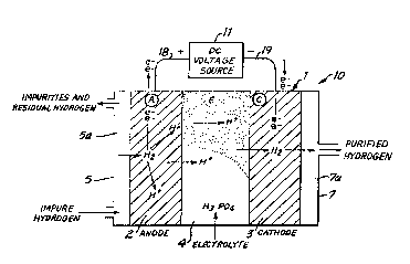
FIG. 1 shows an appa~at~s 10 including an assembly
1 for purifying hydrogen gas in accordance with the
principles of the present invention. The assemb~y 1
comprises an anode electrode 2 and a cathode electrode 3
which sandwich an electrolyte 4. A plate 7 abuts the
cathode electrode 3 and de~ines a gas pas~age 7a for
- :~2~3Z3
receiving hydrogen purified by the a~sembly 1. A
furtherplate 5 abut~ the anode electrode 2 and define~ a gas
pas~ge 5a ~or introducing an impure ~ydrogen ~tream or ~eed
into the as~embly 1.
The apparatus 1 further comprifies a DC voltaye
source, shown as source 11, supplying a voltaye across the
anode and cathode electrodes 2 and 3. Lead 18 connects the
po~itive terminal of ~ource 11 to the anode electrode 2 and
lead 19 connects the negative terminal of the source to the
cathode electrode 3.
The electrolyte 4 between the electrodes 2 and 3
may be an acid electrolyte contained within a microporous
6eparator or membrane. The acid electrolyte i6 preferably
pho~phoric acid becau6e of its stability at elevate~
tcmperature~, although other acid electrolytes such as, ~or
example, sulfuric acid, may al~o be used. The separator
holdinq the acid electrolyte must be made of an electrical
insulator which is stable in the operating environment.
Silicon carbide mixed with Teflon as a binder has been found
stable for u6e in hot phosphoric acid and i3 a preferred
material~ The slectrolyte 4 may also be provided by a solid
polymer type electrolyte such as a solid polymer hydrogen
ion ~xchange membrane.
In accordance with the invention, the anode a~d
cathode electrode~ 2 and 3 are ~ormad as gas diffu ion
electrodes having catalytic ~urfaces. Such electrodes may
generally comprise a porous, conductive layer or sub6~rate
such as, for example, a layer of porous carbon, which ha~
been catalyzed with a ~mall amount of a metallic catalyst,
~uch a~, ~or example, metalliç platinum. l'ypically, the
electrodes should have a porosity of between 50 to 90
percen~ and a metallic catalyst content of between .05 to
0.5 mg/cm2.
~he a~sembly 1 provides purification of the impure
or dilute hydrogen ~tream fed to the pa~sage 5a by ~elective
* Trade-m~rk
,
` ~ '
',`` ' ' :
`
. '
1287323
electrochemical action which separates the hydrogen from the
other ga~e~ in the stream and deliver~ it to the passage
7a~ This selective electrochemical action i~ based upon
hiyhly r0ver~ible hydr~gen oxidation-reduction reactions.
In particular, equations I and II below govern the reactions
at the anode and cathode electrodeA, respectively.
Anode H2(g) ~ ~ 2H~ ~ 2e~ ~I]
Cathode 2H~ + 2e- -------- ~ H2~9) tII]
More specifically, at the anode electrode, the
hydrogen in the impure stream difuses through the electrode
and i8 brought in contact with the metallic catalyst which
iB partially wetted by the acid elec~rolyte. Thera i8
thereby estab}ie~ed the three pha~e interface raquired for
the hydrogen oxidation reaction (conver~ion of molecular
hydrogen to hydrogen ions)0 In the pre~ence of the applied
electrical current, this reaction take~ place and the
hydrogen is ionized and absorbed lnto the electrolyte
according to equation I.
The hydrogen ions in solution are then transported
under the influence o~ the applied electric field to the
cathode electrode 3. At the cathode surface, the hydrogen
ions are reduced by the electrons supplied Prom the external
circuit to produce molecular hydrogen in accordance with
equation II. ~his molecular hydrogen then diffuses through
the pores of the cathode and enters the passage 7a for
delivery from the assembly 1.
only a small electrical potential need be ~lupplied
by the source 11 in ord~r for the hydrogen redox reaction to
take place at a substantial rate. Since the diluent or
impurity gases normally pre~ent in the impure hydrogen
stream are not able to undergo a redox reaction at such a
low applied potential, ~he assembly 1 ig highly selective to
the transfer of hydrogen. The re8ultant molecular hydrogen
produced at the cathode electrode 3 and delivered to the
passage 7a thu~ i~ of very high purity.
~87323
-- 8 --
It should be noted that the amount of electrical
energy expended in the assembly 1 in order to produce a
qiven ~nount of purified hydrog~n depend~ to a large extent
on the electrical re~is~ance exhibited by the assembly.
This fact favors the use of thin, large area components for
the assembly. To this end, FIG. 2 shows the assembly 1
formed from grooved contact plates for the plates 5 and 7.
These plates support thin porous anode and cathode
electrodes 2 and 3 between which is sandwiched a thin porous
membrane 4' filled with electrolyte.
In the case shown in FIG. 2, the paQsaye 5a in the
plate 5 comprise~ channels 5a' whose input and output ends
are open. The open input ends of the channels receive the
impure hydrogen gas and the open output ends exhaust the
impure gase~ and any hydrogen gas not transferred to the
passage 7a by the assembly. The passage 7a, in turn,
comprises channels 7a' which are transverse to the channels
5a'. The channels 7a' are closed at one end and are open at
kheir other end for delivery of the purified
hydrogen from the as~embly 1.
As can be appreciated and a~ shown in FIGS 2 and 3,
the plates 5 and 7, electrodes 2 and 3 and electrolyte
membrane 4' can be repeated to form a stack of assemblies
31. In the case shown, a single plate functions as the
plate 5 of one assembly and the plate 7 of the next
successive assembly via the transverse sets of channels 5a'
and 7a' in its upper and low surfaces.
In such a stack of assemblies, a common input
mani~old 32 receives the impure hydrogen ~rom an inlet port
33 and delivers it to the input ends o~ the channels 5a' o~
assemblies. Purified hydrogen, in turn, exits the
assemblies via the open ends of the channels 7a' and is
collected in a co~non output maniold 34 having àn outlet
port 35. A second common output mani~old 36 receives
the impurities and the non-transferred hydrogen and these
.. .
~8~7323
g
gases èxit the manifold via its outlet port 37.
In the stack shown in FIG. 3, ~he assemblies 1 ar~
compressed between top and bottom 1at compre-qsion plate~ 38
and 39. The plates 38 and 39 are, in turn, secured by cross
members 41, 42 which are hsld together by bolts 43 and
tie-rods 44. The cross member~ are supported by pads 45 on
the plates 38 and 39. Terminals 46 and 47 (not shown)
enable application of the voltage source potential across
the as~emblie~ of the stack.
In a further aspect of the invention, the purified
hydrogen gas provided by the a~sembly 1 may be pressurized
at a pressure higher than that of the impure hydrogen ~eed
stream. This can be accomplished by placing the as~embly in
a pressure vessel and collecting the purified hydrogen gas
at the higher pre~sure.
FIG. 4 shows the stack of FIG. 3 disposed in ~uch a
pressure vesfiel formed from bell shaped ended section3 51
and 52 connected by screws 53 to a main body section 54.
Opening~ 55 and 56 in the section 54 allow for pa~sage of
the ports 37 and 33 of the manifolds 32 and 36 of the fitack
31. The manifold 34 of the stack as shown in FIG. 3 has been
removed and the purified hydrogen is allowed to directly
enter the interior of the vessel and be collected there.
A pressure regulator 61 is disposed in an outlet
port 57 of the vessel. The regulator 61 controls the
pressure of the purified hydrogen leaving the vessel and can
be set at the pressure desired for the purified gas.
The pressure to which the purified gas can be
raiQed is dependent upon the ability of the electrolyte in
each o~ the assemblies 1 to be retained be-tween the assembly
eleatrodes. Where highest pressures are desired, solid
polymer electrolyte~ should be used. Where, however, liquid
electrolytes such as sulfuric or phosphoric acid`are to be
used, the above mentioned silicon carbide membrane augmented
with a layer of ultrafine carbon particles can ba used. In
.
~2~373~3
this casa, the ultrafine carbon layer provideA a membrane
structure with a very ~mall pore diameter and, a~ a re~ult,
the structure afford~ Atrong retention of the electrolyte
via capillary forces.
With the present invention, purified hydrogen c~n
be produced at a pres6ure higher than the preasure of the
impure feed ~tream solely at the expen~e of the energy
required for reversible compression of the hydrogen. The
amount of energy required for reversible separation of n
pound moles of hydrogen at a temperature T is given by the
expression-
W = (2.3 RT)n loglo (P2/Pl) ~III]
where P2 and Pl are deliv~ry and feed pressures, respec-
tively, and R is the gas constant. Reversible work for
separating hydrogen from a feed gas containing 20% hydrogen
at a temperature of 150 C can be calculated from equation
III and is given below for impure hydrogen and purified
hydrogen pressure of 1 and 20 atmospheres.
Impure HydrogenPurified Hydrogen Reveraible Work
20 ~8~P8es~nt)Pressure103xBtu/lb-mol.
(Atm) ~Atm?
1 1 2~43
1 20 6.96
2.43
1 -4.53
Using the above table, the energy needed for
reverslble compre~sion of hydrogen gas from 1 to 20
atmospheres is determined to be 4.53 x 10³ Btu/lb- 1.
With the assembly 1, therefore, only that amount of energy
would be required to provide purified gaY at 20 atmo~pheres
rather than at 1 atmoaphere.
As can be appreciated, a plurality of assemblies
like the assembly 1 can be placed in series to produce an
"' '
~2~373~23
ultrapure hydrogen product. FIG. 5 illustrates a preferred
tandem arrangement of assemblie~ in which the first aesembly
61 in the series utiliz~ phosphoric acid as the electr~lyte
and the ~econd asqembly 62 utiliz0~ ~ ~olid polym~r
electrolyte. With this arrangement, most of the unwanted
impuritie~ in the hydrogen stream including carbon ~onoxide,
are removed or separated from the hydrogen in the first
asqembly 61. The second assembly 62, op~rating on an
essentially carbon monoxide free stream, can then deliver an
ultrapur~ hydrogen gas at elevated pressure.
The energy requirements for operating the as~embly
1 of FIG. 1 are determined by the irreversible losse~
resulting from the electrical resiPtance# of the plates 5
and 7, electrodes 2 and 3, the electrolyte membrane and the
contact resistances. These energy lo~ees appear ae heat in
the a~sembly and serve ~o rai~e ite operating temperature.
The latter temperature, in turn, depend~ upon the impure
feed gas temperature and the current den~ity employed.
Typically, it i~ preferred to operate the assembly dt
temperature~ in a r~nge from 100 - 250~ C w~en phosphoric
acid i8 U8ed ~B the electrolyte. By operating the a~embly
at current den~itie~ in the range of 200 - 600 Ma/cm2, the
afore~aid operating temperature range can be obtained
without the use of ~eparate heating and/or cooling
equipment.
The diluente or impurities in t~e impure hydrogen
feed stream, diffuse through the anode electrode,
electrolyte membrane and cathode electrode of the a~sembly 1
in their normal gaseous state at a low but finite rate. By
increasing the thickness of the electrolyte membrane and
collecting the hydrogen gas at elevated pres~ures, the
diffusion of the unwanted impuritie8 can be decrea6ed.
However, increa~ing the membrane thickne88 increaees its
electrical resistance and thereby the energy requirements
37323
for operating the assembly. Increa~ing purity in this
manner mu~t, therefore, be weighed against any accompanying
increased energy requirements.
AB i~ known, carbon monoxide i8 one of the common
5 impurities found ln conventionally produc~d dilute
hydrogen. Where platinum i8 used as the c~talyst for the
electrodes 2 and 3, carbon monoxide can poison the platinum
catalyst by ad~orbing on the active metal ~ites if the
electrode temperature is too low. ~herefore, when
appreciable concentrations of carbon monoxide are present in
the gas to be purified by the assembly 1, any significant
catalyst poisoning can be eliminated by maintaining the
operating temperature of the cell above 190 C.
FIG. 6 shows current-voltage characteri6tic~ of the
assembly 1 of FIG. 2 utili~ing an electrolyte membrane
having an area of 25-cm2 (0.027 square feet). The
characteristics are for two different impure hydrogen ~eed
stream cOmpOsitiOnQ. As can be seen from these
characteristics, a higher battery potential need6 to be
applied with a lower hydrogen feed concentration t~ overcome
concentration effects and diffusion lo~e~.
The effect of the fraction of hydrogen removed from
the impure feed Qtream on the electrical potential which
needs to be applied to the assembly 1 is shown by the graph~
in FIG. 7. A~ can be seen, the potential remain~
essentially constant until well over 90% of the hydrogen in
the feed stream is removed.
Becau~e of the high trans~er rate of the hydrogen
ion as compar~d to the much slower diffu8ion of th~ g2lseou~
unwanted components through the a8eembly 1, a high degree
o~ separation occurs even in a Bingle stage device. Table 1
in FIG. 8 shows the result~ of product hydrogen analyæis by
gas chromatograph obtained for a 25-cm2 eingle cell
opera~ing at 600 Ma/cm2.
In all cases, it is understood that the
- .:
7323
- 13 -
above-described arrangement~ are merely illustrative of the
many po~sible specific embodimen~s which represent
application~ of the pre~ent invention. Numerou3 and varied
other arrangements can readily be devi~ed in
accordance with the principles of the present invention
without departing from the spirit and scope of the
invention.
~;