Sélection de la langue

Search

Sommaire du brevet 1287401 

Énoncé de désistement de responsabilité concernant l'information provenant de tiers

Une partie des informations de ce site Web a été fournie par des sources externes. Le gouvernement du Canada n'assume aucune responsabilité concernant la précision, l'actualité ou la fiabilité des informations fournies par les sources externes. Les utilisateurs qui désirent employer cette information devraient consulter directement la source des informations. Le contenu fourni par les sources externes n'est pas assujetti aux exigences sur les langues officielles, la protection des renseignements personnels et l'accessibilité.

Disponibilité de l'Abrégé et des Revendications

L'apparition de différences dans le texte et l'image des Revendications et de l'Abrégé dépend du moment auquel le document est publié. Les textes des Revendications et de l'Abrégé sont affichés :

  • lorsque la demande peut être examinée par le public;
  • lorsque le brevet est émis (délivrance).
(12) Brevet: (11) CA 1287401
(21) Numéro de la demande: 1287401
(54) Titre français: METHODE ET DISPOSITIF POUR MESURER LES CHANGEMENTS DE CAPS RELATIFS D'UN SYSTEME DE NAVIGATION EMBARQUE
(54) Titre anglais: METHOD AND APPARATUS FOR MEASURING RELATIVE HEADING CHANGES IN A VEHICULAR ONBOARD NAVIGATION SYSTEM
Statut: Durée expirée - après l'octroi
Données bibliographiques
(51) Classification internationale des brevets (CIB):
(72) Inventeurs :
  • ZAVOLI, WALTER B. (Etats-Unis d'Amérique)
  • MILNES, KENNETH A. (Etats-Unis d'Amérique)
  • PETERSON, GLENN R. (Etats-Unis d'Amérique)
(73) Titulaires :
  • TELE ATLAS NORTH AMERICA, INC.
(71) Demandeurs :
  • TELE ATLAS NORTH AMERICA, INC. (Etats-Unis d'Amérique)
(74) Agent: GOWLING WLG (CANADA) LLP
(74) Co-agent:
(45) Délivré: 1991-08-06
(22) Date de dépôt: 1988-09-28
Licence disponible: S.O.
Cédé au domaine public: S.O.
(25) Langue des documents déposés: Anglais

Traité de coopération en matière de brevets (PCT): Non

(30) Données de priorité de la demande: S.O.

Abrégés

Abrégé anglais


A METHOD AND APPARATUS FOR
MEASURING RELATIVE HEADING CHANGES
IN A VEHICULAR ONBOARD NAVIGATION SYSTEM
Abstract of the Disclosure
A method and apparatus for measuring
relative heading changes in a vehicular onboard
navigation system is provided comprising apparatus for
providing signals corresponding to differential wheel
distance measurements, the velocity and wheel tracking
distance of the vehicle. When front wheel distance
measurements are used in a vehicle having an
Ackerman-type steering system, an apparatus for
providing a signal corresponding to an effective front
wheel tracking distance as a function of the curvature
of turn is also provided.

Revendications

Note : Les revendications sont présentées dans la langue officielle dans laquelle elles ont été soumises.


THE EMBODIMENTS OF THE INVENTION IN WHICH AN EXCLUSIVE
PROPERTY OR PRIVILEGE IS CLAIMED ARE DEFINED AS FOLLOWS:
1. A method of measuring the change in the heading of a
road vehicle during a turn, said vehicle having a pair of
laterally spaced wheels which describe a track having a width,
comprising the steps of:
measuring the distance each one of said wheels is
rotated during said turn;
providing a signal .DELTA.D having a magnitude corresponding
to the difference in the measured distances, one of said wheels 's
rotated relative to the other during said turn;
measuring the velocity of said vehicle during said turn;
providing a signal V having a magnitude corresponding to
said velocity;
providing a signal T having a magnitude corresponding to
said track width;
providing a signal, a, having a magnitude corresponding
to the magnitude of a predetermined constant; and
providing a signal .DELTA..THETA.w with a magnitude which is
directly proportional to said signal .DELTA.D, inversely proportional to
said signal T and a function of said signal, a, and said signal V.
2. A method of measuring the change in the heading of a
road vehicle during a turn, said vehicle having a pair of
laterally spaced wheels which describe a track having a width,
comprising the steps of:
measuring the distance each one of said wheels is
rotated during said turn;
providing a signal .DELTA.D having a magnitude corresponding
to the difference in the measured distances, one of said wheels is
rotated relative to the other during said turn;
measuring the velocity of said vehicle during said turn;
providing a signal V2 having a magnitude corresponding
to the square of said velocity;
providing a signal T having a magnitude corresponding to
said track width;
- 15 -

providing a signal, a, having a magnitude corresponding
to the magnitude of a predetermined constant; and
providing a signal .DELTA..THETA.w with a magnitude determined in
accordance with the following equation:
.DELTA..THETA.w = <IMG>,
wherein said signal .DELTA..THETA.w corresponds to the change in heading of
said vehicle during said turn.
3. A method of measuring the change in the heading of a
road vehicle during a turn, said vehicle having a pair of
laterally spaced wheels which describe a track having a width,
comprising the steps of:
measuring the distance each one of said wheels is
rotated during said turn;
providing a signal .DELTA.D having a magnitude corresponding
to the difference in the measured distances, one of said wheels is
rotated relative to the other during said turn;
measuring the velocity of said vehicle during said turn;
providing a signal V having a magnitude corresponding to
said velocity;
providing a signal T having a magnitude which varies as
a function of a geometric foreshortening of said track width
during a turn of said vehicle; and
providing a signal .DELTA..THETA.w in response to said signals .DELTA.D,
T, and V, wherein said signal .DELTA..THETA.w corresponds to the change in
heading of said vehicle during said turn.
4. A method of measuring the change in the heading of a
road vehicle during a turn, said vehicle having a pair of
laterally spaced wheels which describe a track having a width,
said wheels being laterally spaced by a distance TF in an
Ackerman-type vehicular steering system having a Pitman arm ratio
P which is mounted in a vehicle having front and rear axles which
- 16 -

are separated by a distance B, comprising the steps of:
measuring the distance each one of said wheels is
rotated during said turn,
providing a signal .DELTA.D having a magnitude corresponding
to the difference in the measured distances one of said wheels is
rotated relative to the other during said turn;
providing a signal AD having a magnitude corresponding
to the average distance said wheels rotate;
measuring the velocity of said vehicle during said turn;
providing a signal V having a magnitude corresponding to
said velocity;
providing a signal T with a magnitude determined by the
equation:
<IMG>
and
providing a signal .DELTA..THETA.w in response to said signals .DELTA.D,
T, and V, wherein said signal .DELTA..THETA.w corresponds to the change in
heading of said vehicle during said turn.
5. An apparatus for measuring a change in heading of a road
vehicle during a turn, said vehicle having a pair of laterally
spaced wheels which describe a track having a width comprising:
means for measuring the distance each one of said wheels
is rotated during said turn;
means responsive to said distance measuring means for
providing a signal .DELTA.D having a magnitude corresponding to the
difference in the measured distances one of said wheels is rotated
relative to the other during said turn;
means for measuring the velocity of said vehicle during
said turn;
means responsive to said velocity measuring means for
- 17 -

providing a signal V having a magnitude corresponding to said
velocity;
means for providing a signal T having a magnitude
corresponding to said track width;
means for providing a signal, a, having a magnitude
corresponding to the magnitude of a predetermined constant; and
means for providing a signal .DELTA..THETA.w in response to said
signals .DELTA.D, T, a, and V, wherein said signal .DELTA..THETA.w corresponds to
the change in heading of said vehicle during said turn.
6. An apparatus for measuring a change in heading of a road
vehicle during a turn, said vehicle having a pair of laterally
spaced wheels which describe a track having a width comprising;
means for measuring the distance each one of said wheels
is rotated during said turn;
means responsive to said distance measuring means for
providing a signal .DELTA.D having a magnitude corresponding to the
difference in the measured distances one of said wheels is rotated
relative to the other during said turn;
means for measuring the velocity of said vehicle during
said turn;
means responsive to said velocity measuring means for
providing a signal V having a magnitude corresponding to said
velocity;
means for providing a signal T having a magnitude
corresponding to said track width;
means for providing a signal, a, having a magnitude
corresponding to the magnitude of a predetermined constant; and
means for providing a signal .DELTA..THETA.w with a magnitude
determined in accordance with the following equation:
.DELTA..THETA.w = <IMG> ,
wherein said signal .DELTA..THETA.w corresponds to the change in heading of
said vehicle during said turn.
- 18 -

7. An apparatus for measuring a change in heading of a road
vehicle during a turn, said vehicle having a pair of laterally
spaced wheels which describe a track having a width comprising:
means for measuring the distance each one of said wheels
is rotated during said turn;
means responsive to said distance measuring means for
providing a signal .DELTA.D having a magnitude corresponding to the
difference in the measured distances one of said wheels is rotated
relative to the other during said turn;
means for measuring the velocity of said vehicle during
said turn;
means responsive to said velocity measuring means for
providing a signal V having a magnitude corresponding to said
velocity;
means for providing a signal T having a magnitude
corresponding to said track width which varies as a function of
the curvature of turn of said vehicle; and
means for providing a signal .DELTA..THETA.w in response to said
signals .DELTA.D, T, and V, wherein said signal .DELTA..THETA.w corresponds to the
change in heading of said vehicle during said turn.
8. An apparatus for measuring a change in heading of a road
vehicle during a turn, said vehicle having a pair of laterally
spaced wheels which describe a track having a width, said wheels
being laterally spaced by a distance TF in an Ackerman-type
vehicular steering system having a Pitman arm ratio P which is
mounted in a vehicle having front and rear axles which are
separated by a distance B, comprising:
means for measuring the distance each one of said wheels
is rotated during said turn;
means responsive to said distance measuring means for
providing a signal .DELTA.D having a magnitude corresponding to the
difference in the measured distances one of said wheels is rotated
relative to the other during said turn;
means for providing a signal AD having a magnitude
corresponding to the average distance said wheels rotate;
- 19 -

means for measuring the velocity of said vehicle during
said turn
means responsive to said velocity measuring means for
providing a signal V having a magnitude corresponding to said
velocity;
means for providing a signal with a magnitude determined
by the equation:
T = TF <IMG>
and
means for providing a signal .DELTA..THETA.w in response to said
signals .DELTA.D, T, and V, wherein said signal .DELTA..THETA.w corresponds to the
change in heading of said vehicle during said turn.
9. A method according to claim 1
comprising the step of precomputing said predetermined
constant.
10. A method according to claim 1
comprising the step of changing the magnitude of said
signal, a, as a function of the difference between the
magnitude of said signal .DELTA..THETA.w and the magnitude of a
signal .DELTA..THETA.C wherein said signal .DELTA..THETA.C is provided by a
heading measuring means which is independent of the
means used for providing said signal .DELTA..THETA.w and has a
magnitude corresponding to a change in the heading of
said vehicle as measured by said independent heading
measuring means.
11. A method according to claim 10 wherein
said independent means for providing said signal .DELTA..THETA.C
comprises a compass instrument which is responsive to
the earth's magnetic field and said magnitude of said
signal .DELTA..THETA.C corresponds to a change in the heading of
said vehicle relative to said earth's magnetic field.

12. A method according to claim 10 wherein
said step of changing the magnitude of said signal, a,
comprises the steps of:
providing a signal ERROR having a magnitude
corresponding to the difference between the magnitude
of said signal .DELTA..THETA.C and the then current magnitude of
said signal .DELTA..THETA.w; and
changing the magnitude of said signal, a, as
a function of the relative magnitudes of said signal,
a, before the change and said signal ERROR.
13. A method according to claim 12 wherein
said step of changing the magnitude of said signal, a,
comprises the steps of:
providing a signal aold having a magnitude
equal to the magnitude of the signal, a, before the
change;
providing a signal TC having a magnitude
corresponding to the magnitude of a predetermined
constant; and
providing said signal, a, in response to
said signals ERROR, aOld and TC with a magnitude
determined in accordance with the following equation:
a = aold + <IMG>
14. A method according to claim 10 wherein
said steps of changing the magnitude of said signal,
a, is performed when said change in heading .DELTA..THETA.C
exceeds a predetermined magnitude, said velocity V is
within a predetermined range, and said independent
heading measuring means exceeds a predetermined
accuracy estimate.
21

15. A method according to claim 14 wherein
said predetermined magnitude of .DELTA..THETA.C is approximately
45 degrees and said predetermined range of velocity V
is from approximately 15 to 45 miles per hour.
16. A method according to claim 4 wherein
said step of providing said signal T comprises the
step of providing said signal T from a location in a
table look-up memory which is addressed by an address
corresponding to the curvature of turn of the vehicle
for which the signal T is required.
17. A method according to claim 16 wherein
said step of providing said signal T comprises the
step of addressing said memory using an address
corresponding to the ratio of said signals .DELTA.D and AD.
18. A method of measuring a change in the
heading of a road vehicle during a turn, said vehicle
having a pair of laterally spaced wheels which
describe a track having a width which varies as a
function of the curvature of said turn, comprising the
steps of:
measuring the distance each one of said wheels is
rotated during said turn;
providing a signal .DELTA.D having a magnitude corresponding
to the difference in the measured distances one of said wheels is
rotated relative to the other;
providing a signal T having a magnitude corresponding to
said track width which varies as a function of the curvature of
said turn of said vehicle, wherein said magnitude of said signal T
varies as a function of a geometric foreshortening of said track
width during said turn of said vehicle independently of the
velocity of said vehicle; and
22

providing a signal .DELTA..THETA.w in response to said signals .DELTA.D
and T, wherein said signal .DELTA..THETA.w corresponds to the change in
heading of said vehicle during said turn.
19. A method of measuring a change in the heading of a road
vehicle during a turn, said vehicle having a pair of laterally
spaced wheels which describe a track having a width, comprising
the steps of:
measuring the distance each of said wheels is rotated
during said turn;
providing a signal .DELTA.D having a magnitude corresponding
to the difference in the measured distances one of said wheels is
rotated relative to the other during said turn;
providing a signal T having a magnitude corresponding to
said track width which varies as a function of the geometric
foreshortening of said track width during said turn of said
vehicle independently of the velocity of said vehicle; and
providing a signal .DELTA..THETA.W in response to said signals .DELTA.D
and T, wherein said signal .DELTA..THETA.W corresponds to the change in
heading of said vehicle during said turn.
20. A method of measuring the change in
heading of a road vehicle during a turn, said vehicle
having a pair of laterally spaced wheels which
describe a track having a width which varies as a
function of the curvature of said turn, comprising the
steps of:
measuring the distance each of said wheels
is rotated during said turn;
providing a signal .DELTA.D having a magnitude
corresponding to the difference in the measured
distances one of said wheels is rotated relative to
the other during said turn;
providing a signal AD having a magnitude
corresponding to the average distance said wheels
rotate during said turn;
23

providing a signal T having a magnitude
corresponding to said track width as determined by the
equation:
T = TF <IMG>
wherein TF is the distance said wheels are
spaced apart in an Ackerman-type vehicular steering
system, P is the Pitman arm ratio in said system and B
is the distance between the front and rear axles of
said vehicle; and
providing a signal .DELTA..THETA.w in response to said
signals .DELTA.D and T, wherein said signal .DELTA..THETA.w corresponds
to the change in heading of said vehicle during said
turn.
21. A method according to claim 20 wherein
said step of providing said signal T comprises the
step of providing said signal T from a location in a
table look-up memory which is addressed by an address
corresponding to the curvature of turn of the vehicle
for which the signal T is required.
22. A method according to claim 21 wherein
said step of providing said signal T comprises the
step of addressing said memory using an address
corresponding to the ratio of said signals .DELTA.D and AD.
23. An apparatus according to claim 5
comprising means for precomputing said constant, a.
24

24. An apparatus according to claim 6
comprising heading measuring means which is
independent of the means used for providing said
signal .DELTA..THETA.w for providing a signal .DELTA..THETA.C which has a
magnitude corresponding to a change in the heading of
said vehicle as measured by said independent heading
measuring means and means for changing the magnitude
of said signal, a, as a function of the difference
between the magnitude of said signal .DELTA..THETA.w and the
magnitude of said signal .DELTA..THETA.C.
25. An apparatus according to claim 24
wherein said independent means for providing said
signal .DELTA..THETA.C comprises a compass instrument which is
responsive to the earth's magnetic field and said
magnitude of said signal .DELTA..THETA.C corresponds to a change
in the heading of said vehicle relative to said
earth's magnetic field.
26. An apparatus according to claim 24
wherein said means for changing the magnitude of said
signal, a, comprises:
means for providing a signal ERROR having a
magnitude corresponding to the difference between the
magnitude of said signal .DELTA..THETA.C and the then current
magnitude of said signal .DELTA..THETA.w; and
means for changing the magnitude of said
signal, a, as a function of the relative magnitudes of
said signal, a, before the change and said signal
ERROR.

27. An apparatus according to claim 26
wherein said means for changing the magnitude of said
signal, a, comprises:
means for providing a signal aOld having a
magnitude equal to the magnitude of the signal, a,
before the change;
means for providing a signal TC having a
magnitude corresponding to the magnitude of a
predetermined constant; and
means for providing said signal, a, in
response to said signals ERROR, aOld and TC with a
magnitude determined in accordance with the following
equation:
a = aold + <IMG>
28. An apparatus according to claim 24
wherein said means for changing the magnitude of said
signal, a, is performed when said change in heading
.DELTA..THETA.C exceeds a predetermined magnitude, said velocity V
is within a predetermined range, and said independent
heading measuring means exceeds a predetermined
accuracy estimate.
29. An apparatus according to claim 28
wherein said predetermined magnitude of .DELTA..THETA.C is
approximately 45 degrees and said predetermined range
of velocity V is from approximately 15 to 45 miles per
hour.
30. An apparatus according to claim 7
wherein said signal T providing means comprises means
for providing said signal T with a magnitude which
varies as a function of a geometric foreshortening of
said track width during a turn of said vehicle.
26

31. An apparatus according to claim 8
wherein said means for providing said signal T
comprises means for providing said signal T from a
location in a table look-up memory which is addressed
by an address corresponding to the curvature of turn
of the vehicle for which the signal T is required,
32. An apparatus according to claim 31
wherein said means for providing said signal T
comprises means for addressing said memory using an
address corresponding to the ratio of said signals .DELTA.D
and AD.
33. An apparatus for measuring a change in heading of a road
vehicle during a turn, said vehicle having a pair of laterally
spaced wheels which describe a track having a width which varies
as a function of the curvature of said turn comprising:
means for measuring the distance each one of said wheels
is rotated during said turn;
means responsive to said distance measuring means for
providing a signal .DELTA.D having a magnitude corresponding to the
difference in the measured distances one of said wheels is rotated
relative to the other during said turn;
means for providing a signal T having a magnitude
corresponding to said track width which varies as a function of
the curvature of said turn, wherein said magnitude of said signal
T varies as a function of a geometric foreshortening of said track
width during said turn of said vehicle independently of the
velocity of said vehicle; and
means for providing a signal .DELTA..THETA.w in response to said
signals .DELTA.D and T, wherein said signal .DELTA..THETA.w corresponds to the
change in heading of said vehicle during said turn.
- 27 -

34. An apparatus for measuring a change in heading of a road
vehicle during a turn, said vehicle having a pair of laterally
spaced wheels which describe a track having a width, comprising:
means for measuring the distance each of said wheels is
rotated during said turn;
means responsive to said distance measuring means for
providing a signal .DELTA.D having a magnitude corresponding to the
difference in the measured distances one of said wheels is rotated
relative to the other during said turn;
means for providing a signal T having a magnitude
corresponding to said track width which varies as a function of
the geometric foreshortening of said track width during a turn of
said vehicle independently of the velocity of said vehicle; and
means for providing a signal .DELTA..THETA.w in response to said
signals .DELTA.D and T, wherein said signal .DELTA..THETA.w corresponds to the
change in heading of said vehicle during said turn.
35. An apparatus of measuring a change in
heading of a road vehicle during a turn, said vehicle
having a pair of laterally spaced wheels which
describe a track having a width which varies as a
function of the curvature of said turn, comprising:
means for measuring the distance each of
said wheels is rotated during said turn;
means responsive to said distance measuring
means for providing a signal .DELTA.D having a magnitude
corresponding to the difference in the measured
distances one of said wheels is rotated relative to
the other during said turn;
means responsive to said distance measuring
means for providing a signal AD having a magnitude
corresponding to the average distance said wheels
rotate during said turn;
means for providing a signal T having a
magnitude corresponding to said track width as
determined by the equation:
28

T = TF P + (1-P) x 0.5 + 0.5 1 - <IMG>
wherein TF is the distance said wheels are
spaced apart in an Ackerman-type vehicular steering
system, P is the Pitman arm ratio in said system and B
is the distance between the front and rear axles of
said vehicle; and
means for providing a signal .DELTA..THETA.w in response
to said signals .DELTA.D and T, wherein said signal .DELTA..THETA.w
corresponds to the change in heading of said vehicle
during said turn.
36. An apparatus according to claim 35
wherein said means for providing said signal T
comprises means for providing said signal T from a
location in a table look-up memory which is addressed
by an address corresponding to the curvature of turn
of the vehicle for which the signal T is required.
37. An apparatus according to claim 36
wherein said means for providing said signal T
comprises means for addressing said memory using an
address corresponding to the ratio of said signals .DELTA.D
and AD.
29

Description

Note : Les descriptions sont présentées dans la langue officielle dans laquelle elles ont été soumises.


~7~
A METHOD AND APPARATUS FOR
MEASURING RELATIVE HEADING CHANGES
IN A VE~ICULAR ONBOARD NAVIGATION SYSTEM
Inventors: Walter B. Zavoli
SKenneth Milnes
Glenn Peterson
Background o the Invention
Field of the Invention
The present invention is related in general
to a method and an apparatus for measuring heading
changes of a road vehicle in a vehicular onboard
navigation system, and in particular to a method and
apparatus for measuring relative heading changes in
such a system which comprises differential wheel
distance measurements, velocity measurements, the
wheel track and the wheel base of the vehicle. An
output from a flux gate compass or other independent
means for measuring changes in the heading of the
vehicle may be used from time to time to compensate
for errors in the wheel distance measurements.
Description of Prior Art
In a prior known vehicular dead reckoning
onboard navigation system installed in a wheeled land
vehicle, a display was provided in the vehicle for
displaying a map of the roads in ~he vicinity in which
the vehicle was driven. The vehicle was represented
on the display by a symbol located in the center of
the display.
In operation, as the vehicle was driven in a
straight line along a road, the map was moved in a
straight line on thQ display relative to the symbol.
ETAK5196/WMB12
~4

~Z~4~
--2--
A representation of the road was located thereon in a
position beneath the symbol. When the vehicle reached
an intersection and was turned to be driven along a
second road, i.e. changed heading, the map was rotaked
on the display relative to the symbol by a
corresponding amount. The movement of the map on ~h~
display therefore corresponded, or should have
corresponded, precisely to the movement of the vehicle
along the roads. In practice, however, the signals
used for moving the map on the display were found to
suffer from a certain degree of inaccuracy and were
manifested to an observer of the display by an error
in the displayed position or heading of the vehicle
symbol relative to the map.
One of the sources of the error in the
displayed position or heading of the vehicle was found
to be due to inaccuracies associated with the
measuring of vehicular heading changes.
Heretofore, absolute magnetic as well as
relative heading changes of a vehicle have been
measured using various types of magnetic compasses~
such as, for example, a magnetic flux gate compass and
various types of wheel distance measuring systems such
as, for example, a differential odometer system.
In the operation of the magnetic flux gate
compass, as well as other types of magnetic compasses,
a signal proportional to the strength of the earth's
magnetic field relative to a fixed axis in the
magnetic compass is generated. As a vehicle in which
the magnetic compass is mounted is turned, and the
angle which the axis makes with the earth's magnetic
field changes, the signal generated by the magnetic
ETAK5196/WMB12

~L28~
--3--
compass is generated with a corresponding change in
its magnitude and/or phase.
The accuracy of the output of the magnetic
compass and any change therein depends on the
uniformity of the earth's magnetic ~ield in the
vicinity in which the vehicle is operated. I ~he
vehicle passes through an anomaly in the earth's
magnetic Pield, such as may be caused by a large
building, or if the compass is tilted away from the
horizontal plane as when the vehicle is on a hill,
banked curve, or the like, the output of the magnetic
compass may indicate a heading change which did not
actually occur. Such an occurrence can result in
serious errors in displayed vehicle heading and
position information.
In prior known simple differential odometer
systems of the type used in prior known vehicular
navigation systems as described above and elsewhere
as, for example, U.S. Patent No. 3,845,289, issued to
Robert L. French, a pair of sensors were used for
measuring the distance traveled by the front pair or
rear pair of wheels of a vehicle.
In operation, the sensors in the system
measured the distance traveled by one wheel in the
vehicle relative to the other during a turn. From the
difference in the distances measured during the turn,
a computer generated a signal ~ew corresponding to the
resultant change in the relative heading o~ the
vehicle using the equation
D~,--DR t 1 )
ETAK5196/WMB12

~L28~ 01
where ~ew = change in heading
DL = distance traveled by left wheel
DR = distance traveled by right wheel
T = distance between the two wheels,
e.g. wheel track
In practice, the signal generated using
equation (1) was often found to be inaccura~,
Summary of the Invention
In looking for the source of ~he
inaccuracies found in prior known vehicular
differential odometer systems, it was found that the
magnitude of the inaccuracy generally depended on the
velocity of the vehicle during a turn and on whether
the wheel distance measurements were made from the
front wheels or the rear wheels.
When the measurements are made from the rear
wheels, the source of inaccuracy generally was found
to depend on the velocity of the vehic~e. However,
when the measurements are made using the front wheels
in a vehicle which comprises an Ackerman steering
system, as do most vehicles today, the source of
inaccuracy was found to depend on the velocity of the
vehicle as well as on a change in effective front
wheel trac~. In an Ackerman steering system, it i5
found that the effective wheel track decreases as the
radius of turn decreases.
In view of the foregoing, there is provided
for use in a vehicular onboard navigation system in
accordance with the present invention a novel method
and apparatus for measuring relative heading changes
of a vehicle.
ETAK5196/WMB12

~L28~4~
~5--
In one aspect of the present invention,
there is provided a pair of wheel sensors. The
- sensors are provided for measuring the difference in
distance D traveled by a pair o~ wheels o a vehicle
during a turn. The sensors are located on t~o
laterally opposed wheels of the vehicle, either the
rear wheels or ~he front wheels. In either case, the
wheels are separated by a wheel track aistance T. A
signal corresponding to the velocity V of the vehicle
is also provided.
In operation, relative heading changes of
the vehicle are calculated from the measurements taken
using the equation:
aew = ~D (2)
T(l + aV2)
where ~w = change in heading due to differential
wheel distance measurements
~D = the difference in the distance traveled
by the right and left wheels
T = the wheel track
V = the vehicle velocity
a = a constant
From time to time when the vehicle makes a
turn and the change in direction can be accurately
estimated using other data and measurements available,
the change in heading ~ew, calculated from the
differential wheel distance measurements, is compared
with a corresponding independently measured change in
heading ~h. When a difference is noted, the heading
change ~h is assumed to be the correct heading change
and the magnitude of the constant, a, in equation (2
ETAK5196/WMB12

- ~2~0~
is changed by a relatively small amount in the
direction to make this difference smaller. In this
manner, errors in aew due to errors in the wheel
distance measurements caused ~y forces on the wheel~,
including centripetal orce, loading o the wheels,
tire pressure, etc., are reduced.
In another aspect of the present invention,
when the sensors described above are provided for
measuring the difference in distance traveled by two
laterally spaced front wheels of a vehicle during a
turn, chan~es in the front wheel track during the turn
are also considered. In most modern vehicles the
front wheels are rotated about short axles called
Pitman arms in an Ackerman-type steering system.
lS In an Ackerman-type steering system the
magnitude of the track of the wheels is related to the
curvature of the turn such that
T~ = TE' r+ (l-P) :~/ ~ (3
where TE = the effective track
TF = the track not during a turn
P = the ratio of single Pitman arm length to
one-half the total track (approx. 1/8)
~D = the difference in distance traveled by the
wheels
~D = the average distance traveled by the
wheels
B = the distance between the front and rear
wheel axles (wheel base)
.
ETAK5196/WMB12
~.`, , .

~l~8740~
In the latter aspect, the heading ~0w' is
calculated using equation (1) or (2) wherein T = TE
from equation ~3) above.
The mounting of the sensors to sense the
distance traveled by the driven wheels results in, or
at least ~ignificantly increases the oppoxtunity for,
errors in the measurements of the distances traveled
by the wheels. This is because the driven wheels tend
to slip especially on icy, wet or gravel-type
surfaces. Accordingly, the sensors are mounted to
sense the distance traveled by non-driven wheels ~n
the preferred embodiments of the invention. In four
wheel drive type vehicles, the sensors are typically
mounted for sensing the front wheels because, in
practice, the front wheels are used for driving the
vehicle only part of the time.
The square root operations in equation 3
above typically consume a considerable amount of
computational time. Accordingly, in preferred
embodiments of the present invention there is provided
a look-up memory. In the look-up memory there is
stored a plurality of values of TE, each of which is
calculated usin~ equation 3 for a selected value of
~D/AD.
Brief Description of the Drawing
The above and other objects, features and
advantages of the present invention will become
apparent from the following detailed description of
the accompanying drawings in which:
Fig. 1 is a block diagram of an embodiment
of the present invention;
ETAK5196/WM~12

~8~
Fig. 2 is a geometrical representa~ion o~ a
vehicle making a left turn;
Fig. 3 is a representation of the effective
wheel track of the front wheels of a vehicle in a left
turn; and
Fig. 4 is a geometrical representation o
the effective wheel track of the front wheels o~ a
vehicle in a left turn.
Detailed Description of the Drawing
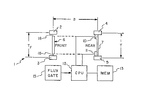
Referring to Fig. 1, there is shown a
representation of a land vehicle designated generally
as 1 comprising a pair of front wheels 2 and 3 and a
pair of rear wheels 4 and 5. The front wheels 2 and 3
are mounted on the axles located on the ends of Pitman
arms 16 in an Ackerman-type steering system designated
generally as 6. The rear wheels ~ and 5 are mounted
on the ends of straight or independent axles
designated generally as 7. The distance between the
front and rear axles is called the wheelbase of the
vehicle and is designated by the letter B. The
distance between the rear wheels ~ and 5 is called the
rear wheel track of the vehicle and is designated by
the letter T. The nominal distance between the front
wheels 2 and 3 of the vehicle, called the nominal
front wheel track, is designated by the letters TF.
The term nominal is used to describe the track when
the vehicle is driven in a straight line because, as
will be further described below, as a vehicle turns,
the front wheel track varies as a function of the
curvature of the turn.
In one embodiment of the present invention,
a pair of wheel- distance measuring sensors la and 11
ETAK5196/WMB12

12~37~0~
is mounted in the vicinity ~f the rear wheels 4 and 5,
Coupled to an output of the sensors 10 and 11 there is
provided a central processing unit 12. Coupled to the
central processing unit 12 there is provided a memory
13 and a conventional flux gate, compass 15 or other
suitable source of heading information.
Referring to Fig. 2, there is shown a
diagram of the vehicle 1 in a left-hand turn wherein
the distance traveled by the right rear wheel DR and
the distance traveled by the left rear wheel DL
subtend an angle ~ew which is equal to a change of
heading ~w of the vehicle. The radius of the arc
described by the right rear wheel 4 is designated RR.
The radius of the arc described by the left wheel 5 i5
designated RL. The difference between the radii RR
and RL is the rear wheel separation previously
designated T.
As can be seen from Fig. 2, the heading
change ~ew of the vehicle 1 can be determined as
follows.
DL = ~ ew x RL
DR = ~ew x RR
where RL = radius of turn for left wheel
RR = radius of turn for right wheel
Subtracting equation (5) from equation (4)
yields
( L DR) - ~ew x (RL ~ RR) (6)
or D - D
L R T ( 7)
ETAK5196/WMB12
:

~ ~287403L
--10--
From the above equation it is clear that aeW
would comprise an accurate measure o the heading
change of the vehicle 1 if the distance traveled by
the wheels 4 and 5 were in exact accordance with
equations (4) and ~5). In practice, however, this is
rarely if ever the case.
During a turn, forces on the wheels are such
that the distance a wheel ~ravels is ~o a better
approximation a non-linear function of the velocity of
the vehicle. To compensate for these forces, the
above equation (7) is modified by a function of V as,
for example, as follows:
~w = ~D (8)
T(l + aV2)
where ~0w = change in heading due to differential
wheel distance measurements
= the difference in distance of travel of
the right and left wheels
T = the wheel track
V = the vehicle velocity
a = a constant
The constant of proportionality, a, varies
among car types, tire characteristics and under
different car loading conditions. In one embodiment
the constant, a, can be precomputed for a given
vehicle or type of vehicle under an average load.
However, in a preferred embodiment of the present
invention, the constant of proportionality, a,
initially comprises a precomputed value and thereafter
is automatically refined as the vehicle is driven.
ETAK5196/WMB12
.
.

~28740~
To refine the constant, a, a change in the
heading of the vehicle ~eC is obtained ~rom, for
example, the flux gate 15 and used as follows.
Let ecl and ewl be compass and wheel
headings before a turn and eC2 and eW2 be compass and
wheel headings after a turn. Then
~ eC = eC2 - e
and
~ew = ewZ ~ eWl = ~D (10)
and
~e ~e, if ~e 2 0
ERROR = w C w (11
~eC ~ ~eW, i~ ~w '
In practice, the magnitude of the ERROR, as
measured in equation (11), is limited when it is used
for refining the constant, a, as follows:
-M if ERROR < -M
ERROR = ERROR i f -M ~ ERROR ~ M (12)
M if ERROR > M
where M = a selected threshold level.
To compute a more stable estimate of the
coefficient a, a filter constant TC is used in the
following equation:
ERROR
a aold TC (13)
where TC = the fil~er distance constant
aOld = the then current constant, a
ETAX5196/WMB12

~Z~741)~
-12-
In the preferred embodiment, the caefficien~
update process of equations (9) through (13) above is
only executed when certain criteria are met indicating
a more accurate estimate of the coefficient, a, can be
calculated. These criteria are 1) a turn of over 45,
2) velocity in the range of 15 to 45 mph ana 3)
consistent compass measurements.
In a second aspect of the present invention,
the sensors 10 and ll are mounted for measuring the
distance traveled by the front wheels 2 and 3 of the
vehicle 1.
Referring to Figs. 3 and 4, it is apparent
that in a turn the effective front wheel track TE can
become substantially smaller than the nominal front
wheel track TF which is the physical separation of the
front wheels. This is because in an Ackerman-type
steering system, the front axle does not remain
perpendicular to the tangent of the turn and
consequently, the tighter the turn the smaller will be
the effective wheel track. It is important to adjust
for this smaller wheel track by computing an effective
track, TE, which compensates for the geometric
foreshortening of the front wheel track during a turn.
TE is then substituted for T in equations ~7) or (8).
The following equation (14) closely
approximates the effective wheel track TE derived from
the geometry of Fig. 4:
TE TF ~ (1 P)~0-5 ~ 0-5~ X(2B)~ 4)
ETAK5196/WMB12

3l 2874~L
-13-
where TE = the ef~ective track during a turn
TF = the track not during a turn
P = the Pitman arm ratio (approximately 1/8)
~D = the difference in distance ~raveled by the
wheels
AD = the average diskance traveled by the
wheels
B = the distance between the ~ront and rear
wheel axles
With the exception of QD and AD, the other
parameters of the above equation can be measured
directly from the vehicle tand are input during
calibration).
The ratio of AD is called a curvature of
turn and represents the rate (over distance not time)
that the vehicle is turning. The above equation,
then, is used to compute an effective track TE which,
in turn, can be used in equation (8) instead of T to
compute an accurate relative heading estimate.
For vehicle navigation the relative heading
must be computed often, approximately once per second,
and the square root operations of the above equation
(14) are computationally time consuming. Therefore,
in the preferred embodiment of the present invention a
plurality of effective tracks TE are computed and
stored in the memory 13 for each of a corresponding
number of the ratios ~D. The set o~ turning
curvatures span the set of realizable turning
curvatures AD starting at 0 for straight dxiving and
going to the maximum curvature for the given vehicle
geometry (approximately .27). With the set of
effective tracks stored in the memory 13, the one
second navigation computation involves only the
~TAK5196/WMB12

~L2!37~
-14-
calculation of AD and a table loo~-up to get the
effective track TE for computing the relative heading.
While a preferred embodiment of the present
invention is described, it is contemplated that
various modifications may be made thereto without
departing from the spirit and scope of the present
invention. Accordingly, it is intended that the
embodiments described be considered only as
illustrative of the invention and that the scope o
the invention be determined by the claims hereinafter
provided.
ETAK5196/WMB12

Dessin représentatif
Une figure unique qui représente un dessin illustrant l'invention.
États administratifs

2024-08-01 : Dans le cadre de la transition vers les Brevets de nouvelle génération (BNG), la base de données sur les brevets canadiens (BDBC) contient désormais un Historique d'événement plus détaillé, qui reproduit le Journal des événements de notre nouvelle solution interne.

Veuillez noter que les événements débutant par « Inactive : » se réfèrent à des événements qui ne sont plus utilisés dans notre nouvelle solution interne.

Pour une meilleure compréhension de l'état de la demande ou brevet qui figure sur cette page, la rubrique Mise en garde , et les descriptions de Brevet , Historique d'événement , Taxes périodiques et Historique des paiements devraient être consultées.

Historique d'événement

Description Date
Lettre envoyée 2002-10-22
Accordé par délivrance 1991-08-06
Inactive : Périmé (brevet sous l'ancienne loi) date de péremption possible la plus tardive 1988-09-28

Historique d'abandonnement

Il n'y a pas d'historique d'abandonnement

Titulaires au dossier

Les titulaires actuels et antérieures au dossier sont affichés en ordre alphabétique.

Titulaires actuels au dossier
TELE ATLAS NORTH AMERICA, INC.
Titulaires antérieures au dossier
GLENN R. PETERSON
KENNETH A. MILNES
WALTER B. ZAVOLI
Les propriétaires antérieurs qui ne figurent pas dans la liste des « Propriétaires au dossier » apparaîtront dans d'autres documents au dossier.
Documents

Pour visionner les fichiers sélectionnés, entrer le code reCAPTCHA :


Pour visualiser une image, cliquer sur un lien dans la colonne description du document (Temporairement non-disponible). Pour télécharger l'image (les images), cliquer l'une ou plusieurs cases à cocher dans la première colonne et ensuite cliquer sur le bouton "Télécharger sélection en format PDF (archive Zip)" ou le bouton "Télécharger sélection (en un fichier PDF fusionné)".

Liste des documents de brevet publiés et non publiés sur la BDBC .

Si vous avez des difficultés à accéder au contenu, veuillez communiquer avec le Centre de services à la clientèle au 1-866-997-1936, ou envoyer un courriel au Centre de service à la clientèle de l'OPIC.

({010=Tous les documents, 020=Au moment du dépôt, 030=Au moment de la mise à la disponibilité du public, 040=À la délivrance, 050=Examen, 060=Correspondance reçue, 070=Divers, 080=Correspondance envoyée, 090=Paiement})


Description du
Document 
Date
(aaaa-mm-jj) 
Nombre de pages   Taille de l'image (Ko) 
Abrégé 1993-10-20 1 19
Revendications 1993-10-20 15 515
Dessins 1993-10-20 1 18
Description 1993-10-20 14 421
Dessin représentatif 2002-03-25 1 7
Taxes 1996-07-14 1 75
Taxes 1995-07-16 1 71
Taxes 1994-07-16 1 78
Taxes 1993-06-20 1 54