Sélection de la langue

Search

Sommaire du brevet 1287455 

Énoncé de désistement de responsabilité concernant l'information provenant de tiers

Une partie des informations de ce site Web a été fournie par des sources externes. Le gouvernement du Canada n'assume aucune responsabilité concernant la précision, l'actualité ou la fiabilité des informations fournies par les sources externes. Les utilisateurs qui désirent employer cette information devraient consulter directement la source des informations. Le contenu fourni par les sources externes n'est pas assujetti aux exigences sur les langues officielles, la protection des renseignements personnels et l'accessibilité.

Disponibilité de l'Abrégé et des Revendications

L'apparition de différences dans le texte et l'image des Revendications et de l'Abrégé dépend du moment auquel le document est publié. Les textes des Revendications et de l'Abrégé sont affichés :

  • lorsque la demande peut être examinée par le public;
  • lorsque le brevet est émis (délivrance).
(12) Brevet: (11) CA 1287455
(21) Numéro de la demande: 1287455
(54) Titre français: DEFLECTEUR SUR DECHARGE D'AIR
(54) Titre anglais: OUTLET PORT BAFFLE FOR EXHAUST AIR
Statut: Durée expirée - après l'octroi
Données bibliographiques
(51) Classification internationale des brevets (CIB):
  • A47L 9/02 (2006.01)
  • A47L 5/00 (2006.01)
  • A47L 5/14 (2006.01)
  • A47L 9/08 (2006.01)
(72) Inventeurs :
  • BERFIELD, ROBERT C. (Etats-Unis d'Amérique)
(73) Titulaires :
  • SHOP-VAC CORPORATION
(71) Demandeurs :
  • SHOP-VAC CORPORATION (Etats-Unis d'Amérique)
(74) Agent: MARKS & CLERK
(74) Co-agent:
(45) Délivré: 1991-08-13
(22) Date de dépôt: 1987-12-21
Licence disponible: S.O.
Cédé au domaine public: S.O.
(25) Langue des documents déposés: Anglais

Traité de coopération en matière de brevets (PCT): Non

(30) Données de priorité de la demande:
Numéro de la demande Pays / territoire Date
114,079 (Etats-Unis d'Amérique) 1987-10-27

Abrégés

Abrégé anglais


ABSTRACT OF THE DISCLOSURE
An outlet port baffle for an air or gas exhaust
port comprises a cylindrical entrance section, a
conical intermediate section terminating in an end
wall. The conical intermediate section has two rows of
apertures extending over an arcuate segment of that
section and has radially projecting, circumferential
ridges which are between and also define the apertures.
Fluid enters the cylindrical section and flows to the
conical section where it is redirected in a direction
normal to its original flow and through the apertures.
The outlet port baffle may be utilized to redirect the
air exhaust from a vacuum cleaner, for example.

Revendications

Note : Les revendications sont présentées dans la langue officielle dans laquelle elles ont été soumises.


- 8 -
THE EMBODIMENTS OF THE INVENTION TO WHICH AN EXCLUSIVE
PROPERTY OR PRIVILEGE IS CLAIMED ARE DEFINED AS FOLLOWS:
1. An outlet port baffle for redirecting
air or gas exiting from an outlet port comprising:
a tubular entrance section for being con-
nected with an outlet port and for receiving air or gas
flowing through the outlet port and for conducting air
therethrough;
a tubular intermediate section communicat-
ing with and forming an extension from the entrance
section for conducting air or gas therethrough, a
plurality of apertures through the intermediate section
arrayed over an arc extending only partially around the
intermediate section, and all of the apertures being
oriented and together covering an arc that is of a
length that air or gas flowing through the apertures
will exit in the same general direction over an arcuate
pathway which is across the path of the air or gas that
has passed into the entrance section and through the
intermediate section; the apertures are arranged in a
plurality of rows of the apertures, with each of the
rows extending along the length of the intermediate
section and the rows together defining the arcuate exit
pathway for the fluid; and
an end section beyond the intermediate
section for blocking passage of air or gas out of the
end of the intermediate section, for redirecting all of
the air or gas out of the apertures of the intermediate
section over the arcuate exit defined by the apertures;
the baffle being angularly movable in the
outlet port to direct the air or gas from the apertures
in a selected direction.

- 9 -
2. The outlet port baffle of claim 1,
further comprising the intermediate section having a
plurality of radially outwardly projecting ridges
projecting radially outwardly from the intermediate
section, and the apertures being defined by and between
neighboring ridges.
3. The outlet port baffle of claim 2,
wherein the ridges extend circumferentially around the
intermediate section.
4. The outlet port baffle of claim 3,
wherein the apertures and the ridges are shaped and
oriented and positioned to redirect air or gas in a
direction generally normal to the direction of flow
through the entrance section.
5. The outlet port baffle of claim 1,
wherein there are at least two apertures in each row of
apertures.
6. The outlet port baffle of claim 2,
wherein the intermediate portion of the baffle is
conically shaped, tapering generally narrower toward
the end section.
7. The outlet port baffle of claim 6,
wherein the entrance section is generally cylindrical
in shape.
8. The outlet port baffle of claim 7,
wherein the baffle sections have a common axis

- 10 -
generally on the path of air entering the entrance
section.
9. The outlet port baffle of claim 3,
wherein the baffle sections have a common axis
generally on the path of air entering the entrance
section.
10. The outlet port baffle of claim 1,
wherein the entrance section is generally cylindrical
in shape.
11. In combination, a vacuum cleaner
having an air inlet, an air outlet port, and collection
means between the air inlet and air outlet part, and
means for moving air from the inlet port through the
collection means and out the outlet port, and
an air outlet port baffle according to
claim 2, wherein the entrance section of the outlet
port baffle is removably connectable in and angularly
rotatable in the outlet port of the vacuum cleaner and
the outlet port and entrance section of the outlet port
baffle are respectively so shaped as to enable the
angular position of the outlet port baffle with respect
to the vacuum cleaner to be adjusted for placing the
apertures in any selected angular position around the
axis of the outlet port baffle.

Description

Note : Les descriptions sont présentées dans la langue officielle dans laquelle elles ont été soumises.

~ 28'7455
SV-137 (35-973)
OUTLET PORT BAFFLE FOR EXHAUST AIR
BACKGROUND OF THE INVENTION
1. Field of the Invention
The present invention relates to an outlet port
baffle, and, more particularly, to an exhaust air
outlet port baffle, particularly for a vacuum cleaner.
2. Description of the Related Art
Many models of vacuum cleaners have an exhaust
port into which a hose or tool can be inserted to
utilize the air for blowing purposes. This port
usually is aimed to direct the air either upwardly or
horizontally away from the vacuum cleaner. However,
when a hose or tool has not been inserted into the
port, there is an undesirable blast of exhaust air
straight out of the port.
Various attempts have been made to control the
orientation of the blast of air from an exhaust port~
such as utilizing an elbow fitting which redirects the
air flow in a direction across, and particularly
normal, to its original flow. Two-piece fittings,
comprising an elbow fitting and a cap fitting placed at
:

~l28~455
the outlet from the elbow, have also been used to
provide additional baffling of the air from the exhaust
port.
It is, of course, well known to provide nozzles
- 5 for directing fluids exiting an orifice. U.S. Patent
No. 3,997,116 to Moen discloses a shower head nozzle
having numerous rid~es and apertures located in arcuate
segments exten~ing 360 around the body of the shower
head.
U.S. Patent No. 2,793,912 to Krohm discloses a
nozzle assembly for applying windshield washer fluid to
an automobile windshield. The assembly comprises an
anchor piece for placement in the body of the
automobile and a nozzle piece which is radially
adjustable within the anchor piece.
U.S. Patent No. 4,284,241 to Azalbert discloses
a spray nozzle for distributing fluid. The nozzle is a
cylindrical body with an end cap. Numerous
longitudinal triangular apertures are provided in the
nozzle.
U.S. Patent No. 3,497,141 discloses a hose
nozzle spray attachment for a fire hose. The
attachment is a conical member having an end cap which
baffles the water from a fire hose.
These attempts in the prior art to direct
fluids from an e~it orifice have resulted in unsightly
fittings having limited ability for precisely
redirecting the fluid from the exit orifice.

~ ~ 2~7~55
SUMMARY OF THE INVENTION
Accordingly, an object of the present
invention is to provide an outlet port baffle which
redirects gas or air in a direction across, and more
particularly normal, to the original direction of air
exiting from the outlet port.
Another object is to provide an outlet port
baffle having the ability to redirect gas or air in a
direction across or normal to its oriqinal direction
and through an accurate segment of the baffle.
Yet another object is to enable the
direction of outflow from the port to be adjustable.
A further object of the present invention
is to provide an outlet port baffle that is
aesthetically pleasing.
These and other objects of the present
invention are achieved with an air or gas outlet port
baffle defined along one axis and which has three
sections. The entrance section for connection with,
e.g. insertion into, the outlet port is generally
cylindrical. The intermediate section is conical. It
has a series of radially projecting, circumferentially
extending ridges which are adjacent to and define a
series of apertures into the intermediate section. The
apertures are preferably arranged in two axially
extending rows of apertures which rows together extend
over an arcuate segment of the intermediate section and
preferably over a 180 arc segment. The outlet section
is an end cap oriented across, and particularly normal,
to the oriqinal direction of the air or gas flow, and
~'
,~ .

- ~2~74~5
-- 4 --
which blocks passage through the end of the baffle and
forces the air or gas through the apertures,
The outlet port baffle of the present invention
is slidable and adjustable in the outlet orifice so
that it may be rotated in its orientation to cause the
air or gas outlet apertures to be directed in any
direction around the axis of the baffle.
Other objects and features of the invention are
seen from the ~ollowing description and accompanying
drawings.
BRIEF DESCRIPTION OF THE DRAWINGS
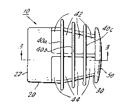
Fig. l shows a top view of the outlet port
baffle of the present invention.
Fig. 2 shows an end view of the baffle of the
present invention.
Fig. 3 shows a cross section vie~ along lines
A-A of Fig. l.
Fig. 4 shows the present invention in use with
a vacuum cleaner apparatus.
DETAILED DESCRIPTION OF THE PREFERRED EMBODIMENT
The outlet port baffle 10 of the present
invention comprises an entrance section 20r an
intermediate section 30 and an outlet end section 50.
The outlet port baffle of the present invention may be
formed of any suitable material, but is preferably of
molded plastic.
Entrance section 20 comprises a cylindrical
tubular portion having an entrance fitting 22. Fitting

1287455
22 is received into the output port or orifice of the
exhaust port of a vacuum cleaner, for example, to
receive the air or gas from the orifice.
Entrance section 20 is integral with and leads
into air or gas redirecting, intermediate section 30.
Intermediate section 30 is also tubular. It has a
generally conical shape tapering narrower toward the
outlet end section 50. The intermediate section 30 and
possibly also the downstream end of the entrance
section 20 together have two parallel, longitudinally
extending rows of apertures 42 and 44, for directing
the gas or air radially outward of the intermediate
section 30. Each aperture is shorter in its dimension
axially of the baffle, and arcuately or circumferen-
tially of the baffle it is much wider. The rows ofapertures are arranged laterally together to together
define an arcuate segment shaped open region around the
baffle, and to direct the outflow of gas or air over
the arc. The drawings illustrate that the apertures
permit air dispersal over a 180 arc. Any arcuate
angle segment of the baffle section 30 may be occupied
by the exit apertures, so long as the apertures direct
flow generally toward one direction.
Circumferentially extending, radially project-
ing ridges 40a, 40b, and 40c project from the inter-
mediate section 30. They separate adjacent apertures
42, 42 and 44, 44 and they assist in the redirection of
the gas or air. The ridges are shown as oriented to
direct the air or gas radially outward. But, they may
be otherwise oriented to angle the air flow obliquely
with respect to the axis of the section 30.

1~8~4~s
The end section 50 is integral with the
intermediate section 30. End section 50 comprises an
end cap to block the flow of air or gas and thereby to
redirect the flow from its original direction,
illustrated by the arrow in Fig. 1, to flow out
apertures 42 and 44 over an arcuate segment and normal
to the original flow, as illustrated in Fig. 2.
In operation, fitting 22 of the outlet port
baffle 10 is placed in the air or gas exhaust or outlet
orifice of an apparatus. Air or gas flowing from the
apparatus enters entrance section 20 and passes through
intermediate section 30 where it is redirected by end
section 50 through apertures 42 and 44.
In a preferred embodiment in Fig. 4, the
outlet port baffle 10 is used to redirect the exhaust
airblast exiting a vacuum cleaner 60. Vacuum cleaner
60 is a standard canister type vacuum cleaner having
air moving fan motor housing 62 and suction inlet
nozzle connector 64. Air flows through the collecting
tank beneath housing 62 and then out exhaust outlet
port 66. The entrance section 20 of outlet port baffle
10 is placed in port 66. ~xhaust air is redirected
through apertures 42 and 44. The outlet port baffle is
slidably adjustable angularly by rotation around its
axis in air outlet port 66, so that the user may direct
the exiting redirected air in any direction, that is
over any segment of a 360 arc.
Although the present invention has been
described in connection with a preferred embodiment
thereof, many other variations and modifications will

-` ~l2~374S5
-- 7
now become apparent to those skilled in the art. It is
preferred, therefore, that the present invention be
limited not by the specific disclosure herein, but only
by the appended claims.

Dessin représentatif
Une figure unique qui représente un dessin illustrant l'invention.
États administratifs

2024-08-01 : Dans le cadre de la transition vers les Brevets de nouvelle génération (BNG), la base de données sur les brevets canadiens (BDBC) contient désormais un Historique d'événement plus détaillé, qui reproduit le Journal des événements de notre nouvelle solution interne.

Veuillez noter que les événements débutant par « Inactive : » se réfèrent à des événements qui ne sont plus utilisés dans notre nouvelle solution interne.

Pour une meilleure compréhension de l'état de la demande ou brevet qui figure sur cette page, la rubrique Mise en garde , et les descriptions de Brevet , Historique d'événement , Taxes périodiques et Historique des paiements devraient être consultées.

Historique d'événement

Description Date
Inactive : Périmé (brevet sous l'ancienne loi) date de péremption possible la plus tardive 2008-08-13
Inactive : CIB de MCD 2006-03-11
Lettre envoyée 2003-02-25
Accordé par délivrance 1991-08-13

Historique d'abandonnement

Il n'y a pas d'historique d'abandonnement

Titulaires au dossier

Les titulaires actuels et antérieures au dossier sont affichés en ordre alphabétique.

Titulaires actuels au dossier
SHOP-VAC CORPORATION
Titulaires antérieures au dossier
ROBERT C. BERFIELD
Les propriétaires antérieurs qui ne figurent pas dans la liste des « Propriétaires au dossier » apparaîtront dans d'autres documents au dossier.
Documents

Pour visionner les fichiers sélectionnés, entrer le code reCAPTCHA :


Pour visualiser une image, cliquer sur un lien dans la colonne description du document. Pour télécharger l'image (les images), cliquer l'une ou plusieurs cases à cocher dans la première colonne et ensuite cliquer sur le bouton "Télécharger sélection en format PDF (archive Zip)" ou le bouton "Télécharger sélection (en un fichier PDF fusionné)".

Liste des documents de brevet publiés et non publiés sur la BDBC .

Si vous avez des difficultés à accéder au contenu, veuillez communiquer avec le Centre de services à la clientèle au 1-866-997-1936, ou envoyer un courriel au Centre de service à la clientèle de l'OPIC.


Description du
Document 
Date
(aaaa-mm-jj) 
Nombre de pages   Taille de l'image (Ko) 
Page couverture 1993-10-21 1 11
Abrégé 1993-10-21 1 16
Revendications 1993-10-21 3 85
Dessins 1993-10-21 1 25
Description 1993-10-21 7 187
Dessin représentatif 2000-07-27 1 6
Taxes 1994-07-18 1 77
Taxes 1996-07-18 1 75
Taxes 1993-07-12 1 62
Taxes 1995-07-20 1 85