Note : Les descriptions sont présentées dans la langue officielle dans laquelle elles ont été soumises.
oo~
BACKGROUND OF THE INVENTION
The present invention relates to a method of building refrac-
tory protection walls of ovens, furnaces and combustion chambers, and to
a fire-brick for carrying out said method.
S This invention is applicable notably but not exclusively to the
constxuction of boilers or furnaces for protecting the hearth walls the-
reof. More particularly, the present invention is intended for protecting
boilers in which the hearth walls are provided with tubular panels, no-
tably in the case of town refuse or garbage incineration boilers.
10 THE PRIOR ART
A boiler of this type is well known nowadays which comprises es-
sentially a combustion chamber which, in the case of an incineration
plant, permits of burning up household and industrial refuse and have
their inner walls equipped with heat regenerators for recovering the po-
15 tential thermal energy stored in the refuse.
In fact, some known combustion chambers have their inner walls
lined with so-called tubular panels made from tubular elements and fins
welded thereto, a heat-conveying fluid being caused to flow through the
panels heated during the combustion.
However, to protect such tubular panels from severe heat- and
mechanical stress and from the attack of chemical and abrasive substan-
ces, they must be protected by a refractory or fire wall warranting a
longer useful life of the structure.
In the conventional method of building tubular panels, said tubes
25 are spaced from one another but not assel~bled through their fins, so that
suitably shaped fire-bricks can be disposed between the tubes for complet-
ing the protection fire-wall. Now this method is no more applicable to
panels consisting of an assembly of tubes and fins welded thereto since
it is not possible to insert fire-bricks between a pair of ad~acent tubes
30 due to the presence of said fins.
In a known attempt to palliate this inconvenience, fire-bricks
and refractory plates provided with transverse holes have been proposed
so that the bricks can be fitted to the tubular panels by means of fast-
ening means such as screws, rivets or T-shaped locking lugs extending
35 therethrough.
This solution is objectionable because on the one hand it impairs
the strength of the fire-bricks, due to the presence of the through-holes,
and on the other hand each fixation hole must subsequently be stopped.
- 2 -
fiO~3
SUMMARY OF THE INVENTION
A feature of one embodiment of the present inven-
tion provides a method of building reEractory inner
protection walls for furnaces, ovens or combustion
chambers, which avoids the inconveniences of prior art
structures and on the one hand neither impairs the
mecnanical strength of the Eire-bricks, nor requires any
sealing or stopping operation when fitted in position.
It is a feature of another embodiment of the pre-
sent invention to provide a fire-brick for protecting
tubular panels, this brick having a shape consistent
with the panel configuration and a plain, solid surface
on the boiler or furnace side, and adapted to be easily
fitted to the wall panels.
Another feature of another embodiment of the pre-
sent invention provides an improved method of building
refractory panels for protecting the walls of furnaces,
ovens and combustion chambers by means of fire-bricks
having a configuration such that they can be fitted in
staggered relationship to prevent any air-flue effect
through the brick sealing joints.
Furthermore, a feature of another embodiment of
this invention provides a method of building refractory
protection walls by using fire-bricks which are charac-
terized by a reliable, efficient fluid-tightness.
A complementary feature of an embodiment of the
present inven-tion provides a method of building
refractory protection walls from fire-bricks so shaped
that they are self-fixing and self-locking in the final
structure.
Other features and advantages of the present
invention will appear as the following description
proceeds which is given by way of example, not of
limitation.
In accordance with an embodiment of the present
invention there is provided a method of building
~'~,.
.~, ~
J~OO~
refractory protection walls of furnaces, ovens or
combustion chambers, for boilers or the like for
incinerating household refuse, garbage or industrial
waste or refuse, for protecting hearth walls, the hearth
walls consisting of panels consisting of a cluster of
tubes assembled by welded fins, wherein the refractory
protection wall consists of a plurality of shaped fire-
bricks having inner and outer surfaces, the method
comprising the steps of: providing at least one blind
o recess on the inner surfaces of each of the fire-bricks;
providing the panel to be protected with a plurality of
fixing studs adapt~d to correspond to and engage at
least one blind recess of each of the fire-bricks;
suspending each of the fire-bricks from a corresponding
fixing stud or studs wherein the fire-bricks are held in
position by gravity and wherein the fire-bricks are
positioned in overlying adjacent relationship.
In accordance with another embodiment of the pre-
sent invention there is provided a fire-brick for use in
refractory wall composed of a plurality of shaped fire-
bricks for the protection of a hearth wall, the hearth
wall being provided with panels composed of a cluster of
tubes assembled by welded fins and having a plurality of
fixing studs, the fire-bricks having a volumetric
configuration consistent with the panel, each fire-brick
having an inner face and an outer face, and comprising
on its inner face at least one blind recess having a
longitudinal axis extending across and inclined to the
inner face, the fixing studs of the panels ~atching with
and being adapted to engage the blind recesses of the
plurality of fire-bricks composing the refractory wall,
each of the fire-bricks being suspended from correspon-
ding fixing studs to be held in position by gravity and
self-locked at least by the overlying adjacent fire-
brick of the refractory wall.
A clearer understanding of the present invention
a~t,!'
.OC~3
- 4a -
will be had from the following description given with
reference to the attached drawings.
THE DRAWINGS
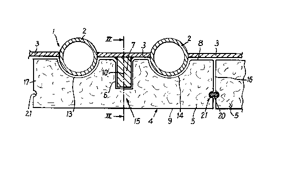
Figure 1 is a fragmentary section taken across a
combustion chamber equipped with a tubular panel
protected according to the teachings of the present
invention;
Figure 2 is a longitudinal section taken along the
line II-II of Figure l; and
Figure 3 is a fragmentary view showing one face of
a refractory protection wall according to the instant
invention.
DESCRIPTION OF THE PREFERRED EMBODIMENT
The present invention is directed to the building
of refractory walls for protecting furnaces, ovens or
combustion chambers consisting as a rule of a hearth in
which the combustion takes place and having its walls
provided with a heat exchanger capable of collecting the
heat released by the combustion for reheating a heat
conveying fluid for the purpose of delivering heat to
another device.
Furnaces, ovens or combustion chambers of this type
are used in general but not exclusively in boilers for
incinerating town or household refuse or garbage, as
well as industrial refuse or waste.
As clearly shown notably in Figure 1, the hearth
walls are provided with tubular panels 1 consisting in
turn of tubes 2 interconnected by welded fins 3 and
intended for circulating the heat-conveying fluid.
In the method of the present invention the refrac-
tory wall 4 consists of a plurality of shaped fire-
bricks 5, as follows:
- each fire-brick 5 comprises at least one blind
recess 6 disposed at the level of the fixing means
contemplated;
-` ~ 2~3~003
- the panel 1 to be protected is provided with a plurality of
projecting fixing studs 7 matching with and adapted to engage said blind
recesses 6 of fire-bricks 5,
- each fire-brick 5 is suspended from the corresponding fixing
5 stud or studs 7 and thus held in position by gravity, the fire-brick
being furthermore self-locked at least by the overlying adjacent fire-
brick 5.
As shown in Figures 1 and 2, the fire-bricks 5 have a volumetric
shape consistent with the panel 1 and comprise an inner face 8 and an
10 outer face 9.
The inner face 8 of each fire-brick 5 is shaped to accomodate
the tubes 2 of tubular panel 1 and the outer face 9 is part of the sur-
face of the refractory protection wall, on the hearth side.
According to the present invention, each fire-brick 5 has formed
15 on it inner face 8 at least one blind recess 6 having a longitudinal
axis 10 extending across the fire-brick thickness and inclined at an an-
gle a to said inner face 8.
According to a preferred form of embodiment of the present inven-
tion, this angle a will advantageously lie in the range of 45 - 90,
20 and the longitudinal axis 10 will extend upwardly to impart the self-
locking feature to the fire-brick 5 by mere gravity, as actually shown
in Figure 2.
In another preferred form of embodiment, each fire-brick 5 has
two blind recesses 6, 11 formed therein, the longitudinal axes 10, 12
25 respectively of which being disposed in a common axial plane substantial-
ly at right angles to the inner face 8. Furthermore, these axes 10, 12
are substantially parallel to each other. Thus, when fitting the fire-
brick in position, any undesired pivoting movement thereof with res~ect
to its fixing stud 7 will be safely prevented.
Moreover, as also shown in Figure 1 the inner face 8 of fire-
brick 5 has two spaced grooves 13, 14 of semi-circular cross-sectional
configuration formed therein. The distance between centres of these
grooves 13, 14 corresponds substantially to that of said tubes 2. In
this case, the blind recess or recesses 6, 11 are disposed in the thick-
35 est area 15 of the fire-brick, for example substantially midway of said
grooves 13, 14.
In fact, according to the method of the present invention, the
blind recesses 6, 11 as well as the corresponding fixing studs 7 pro-
vided for suspending and self-locking the fire-bricks 5 are disposed
- 5 -
~ 2~.00;~
in staggered relationship to prevent any undesired "flue effect" fromdeveloping in the jointing of the fire-bricks, as shown more particu-
larly in Figure 3.
This arrangement is made possible notably by the fact that each
5 fire-brick 5 covers a pair of adjacent tubes 2 and is suspended from, and
secured by, the corresponding fixing studs 7 projecting from the fin 3
disposed between, and welded to, said pair of adjacent tubes 2. The a-
bove-described form of embodiment of fire-brick 5 is perfectly suitable
to this staggered fitting method.
However, other fire-brick sizes may be contemplated, notably
when it is desired that each brick covers three tubes or more, without
departing from the basic principle of the invention.
When carrying out the method of the present invention by build-
ing a refractory protection wall structure consisting of a plurality of
15 fire-bricks 5, each fire-brick is provided with a pair of blind recesses
6, 11 disposed substantially along a common vertical axis, and fixing
studs 7 having a configuration consistent with that of said blind re-
cesses are welded to the fins 3 of tubular panels 1 according to the di-
mensions of each fire-brick 5.
Thus, by welding the fixing studs 7 to said fins 3, the mechanic-
al strength of tubes 2 constituting the panels 1 is not impaired. How-
ever, it is quite possible to weld these fixing studs 7 to the tube gene-
ratrices, provided that the bricks and their recesses are designed ac-
csrdingly .
Finally, when building a refractory protection wall separating
the combustion chamber from the tubular panel according to the method of
the present invention, the fluid-tightness between ad~acent fire-bricks
5 is obtained by providing a refractory seal 20 between each top, bottom
and lateral face 16 - 19 of fire-bricks 5.
For this purpose, each top, bottom and lateral face 16 - 19 of
fire-bricks 5 has a relatively shallow groove 21 formed therein for re-
ceiving this refractory seal 20.
This seal 20 may consist of any suitable refractory material pre-
serving a certain resiliency even at high temperature, as will readily
35 occur to those conversant with the art.
Of course, other forms of embodiment may be devised for the pre-
sent invention without departing from the basic principles thereof.