Sélection de la langue

Search

Sommaire du brevet 1288056 

Énoncé de désistement de responsabilité concernant l'information provenant de tiers

Une partie des informations de ce site Web a été fournie par des sources externes. Le gouvernement du Canada n'assume aucune responsabilité concernant la précision, l'actualité ou la fiabilité des informations fournies par les sources externes. Les utilisateurs qui désirent employer cette information devraient consulter directement la source des informations. Le contenu fourni par les sources externes n'est pas assujetti aux exigences sur les langues officielles, la protection des renseignements personnels et l'accessibilité.

Disponibilité de l'Abrégé et des Revendications

L'apparition de différences dans le texte et l'image des Revendications et de l'Abrégé dépend du moment auquel le document est publié. Les textes des Revendications et de l'Abrégé sont affichés :

  • lorsque la demande peut être examinée par le public;
  • lorsque le brevet est émis (délivrance).
(12) Brevet: (11) CA 1288056
(21) Numéro de la demande: 1288056
(54) Titre français: DEFLECTEUR INSONORISANT POUR REGISTRE
(54) Titre anglais: NOISE REDUCTION SPOILER FOR A DAMPER
Statut: Durée expirée - après l'octroi
Données bibliographiques
(51) Classification internationale des brevets (CIB):
  • F01N 01/16 (2006.01)
  • F16K 01/22 (2006.01)
  • F16K 47/02 (2006.01)
  • F24F 13/14 (2006.01)
(72) Inventeurs :
  • INGLIS, STEPHEN C. (Etats-Unis d'Amérique)
(73) Titulaires :
  • CARRIER CORPORATION
(71) Demandeurs :
  • CARRIER CORPORATION (Etats-Unis d'Amérique)
(74) Agent: GOWLING WLG (CANADA) LLP
(74) Co-agent:
(45) Délivré: 1991-08-27
(22) Date de dépôt: 1987-09-25
Licence disponible: S.O.
Cédé au domaine public: S.O.
(25) Langue des documents déposés: Anglais

Traité de coopération en matière de brevets (PCT): Non

(30) Données de priorité de la demande:
Numéro de la demande Pays / territoire Date
925,939 (Etats-Unis d'Amérique) 1986-10-31

Abrégés

Abrégé anglais


NOISE REDUCTION SPOILER FOR A DAMPER
ABSTRACT OF THE DISCLOSURE
A spoiler is located on the damper blade of a damper assembly
such that it serves to divert the flow from the hinge area to
avoid air separation. Further, the spoiler does not define
the most restricted portion of the flow path and thereby has
a minimal effect on the flow resistance.

Revendications

Note : Les revendications sont présentées dans la langue officielle dans laquelle elles ont été soumises.


CLAIMS
What is claimed is:
1. A damper assembly comprising
a housing having an inlet and an outlet and a flow
path therebetween;
a damper shaft extending transversely across said
flow path;
an S shaped damper blade having an upstream and a
downstream side and pivotably mounted in said housing about
said damper shaft;
a first seal means for coacting with said upstream
side;
a second seal means for coacting with said down-
stream sides
said damper blade being movable between a closed
position coacting with said first and second seal means and a
fully open position wherein said damper blade presents the
minimum projected area relative to said flow path;
a spoiler means mounted on said downstream side of
said damper blade at a point upstream of said damper shaft
when said damper blade is in said fully open position;
said spoiler means including a pair of arms forming
a blunt V and located downstream of said second seal means
when said damper blade is in the fully open position.
2. The damper assembly of claim 1 wherein said
pair of arms make an angle of approximately 135°.
3. The damper assembly of claim 1 wherein one of
said pairs of arms is one half to one inch long.

Description

Note : Les descriptions sont présentées dans la langue officielle dans laquelle elles ont été soumises.

2 ~ 8 05 6
NOISE REDUCTION SPOILER FOR A DAMPER
Back~round of the Invention
The present invention relates to damper structures and more
specifically to the reduction of low frequency noise in
damper structures.
Air flow structures such as da~pers are subject to
self-generated noise which is a function of the velocit~ and
pressure of the delivered air as well as the structural
details of the air distribution system. ~ecause the duct
opens into the room or zone through one or more terminals,
the noise may be delivered along with the conditioned air.
There is an apparently random distribution of the noise but
the noise generation is greatest at lower static pressures
where a hollow whistle akin to that resulting from blowing
over a bottle is produced. The noise generation is apparent-
ly the result of air separation at the hinge area due to the
transition in the damper blade.
Summary of the Invention
The present invention reduces low frequency noise in the
damper by attaching a spoiler to the damper in the hinge area
on the downstream side of the dam*er. The noise is generally
retuced but there is a relatively small increase in noise at
some frequencies. Thus, there are tradeoffs resulting in
reduction of noise at the loudest and/or most irritating
; frequencies but the net result is a general noise reduction.
~-~ 30 It is an obj ect of this invention to reduce the overall noise
levels in a damper unit.
.,
It is another object of this invention to reduce the noise
created by air separation at the blade attachment point.
~g

05~
It is an additional object to provide a more uniform air
distribution when the damper is nearly closed.
It is a further object of this invention to reduce the
overall noise levels in a damper unit without sacrificing the
pressure drop in the wide open position. These objects, and
others as will become apparent hereinafter, are accomplished
by the present invention.
Basically, in a damper unit where the damper blades make a
stylized S ~n cross section and the hinge is located at the
transition area, a spoiler is located on the downstream side
of the damper at a point upstream o~ the hinge to thereby
direct the flow away from the hinge area. In the open
position this reduces the noise and when the damper is nearly
closed it spreads the air rather than letting it hug the
damper blade.
Brief Description of the Drawings
For a fuller understanding of the present invention, refer-
ence should now be made to the following detailed description
thereof taken in conjunction with the accompanying drawings
wherein:
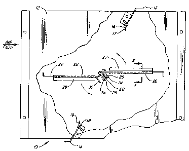
Figure l is a partially cutaway side view of a damper assem-
bly in a full open position;
Figure 2 is a sectional view taken along line 2-2 of Figure
l ;
Figure 3 is a side view of the damper blade and spoiler
assembly; and
Figure 4 is a table showing the radiated noise or sound power
level for various flow volumes and pressure drops.

Description of the Preferred Embodiment
In Figure 1, ~he numeral 10 generally designates a damper
assembly. The damper assembly 10 includes a housing 12
defining a flow path with a pair of angle members 13 and 14.
Seals 16 and 18 are suitably secured to angle members 13 and
14, respectively, and include arms 17 and 18 which, respec-
tively, serve as the top and bottom seals or seats. Damper
shaft 20 extends through opposite sides of housing 12 and is
received in bearings (not illustrated) for rotary movement
therein. One end of the damper shaft 20 is connected to an
operator (not illustrated) for causing the rotation of damper
shaft 20. Damper blade 22 is secured to shaft 20 by a
plurality of bolts 24 and nuts 25 and rotates therewith as a
unit. As best shown in Figure 3, the damper blade 22 is
shaped like a stylized S from the side. Four side seals
including two upper seals 26 and two lower æeals 28 are
suitably secured to the ends of tamper blade 22 and include
arms 27 and 29, respectively which coact with the sides of
housing 12 in a sealing relationship. Although the shaft 20
is illustrated as located on the downstream side of the
stylized 5, it could also be located on the upstream side.
The device so far described has an unsuitable performance for
;~ some operating conditions due to noise generation. This
noise generation is apparently due to air separation in the
hinge area defined by shaft 20~ It will be noted that the
shaft 20 is located in the transition area of the stylized S
at a downstream location and at this location the flow path
restricts along the top or upstream face of damper blade 22
;~ 30 and expands along the bottom or downstream face of damper
blade 22. At low static pressure, the expanding flow path is
most likely to cause air separation and the resultant noise
generation. The projected image of the damper blade in the
full open position corresponds to that of the damper shaft so
th~t the area of the flow path through the damper is essen-
tially maximized for the location of seals 16 and 18 which
:`

~-~s~o~
-~ 4
define the opening. In reducing the noise it is essential to
avoid sacrificing the pressure drop in the wide open
position.
As best illustrated in Figure 3, a spoiler 30 is secured by
rivets 40, or other suitable means, to the downstream side of
damper blade 22 at a location which is upstream of the
position of damper shaft 20 when the damper blade 22 is in
the full open position even when shaft 20 is located on the
upstream side of the stylized S. Spoiler 30 includes two
arms 31 and 32 making an angle of approximately 135 to form
a blunt V. Arm 31 has a length of one half to one inch with
three fourths inch preferred. Referring now to Figure 1
where the damper blsde 22 is in the full open position where
it is desired to ha~e the least flow resistance, it will be
noted that the divided flow paths through the damper assembly
10 are different. In the flow path partially defined by the
upstream side of damper blade 22, the cross sectional area of
the flow path is reduced at the transition area of the damper
blade 22 where the damper shaft 20 is located and is further
restricted downstream by seal 16. In contrast, in the flow
path partially defined by the downstream oide of the damper
blade 22, the cross sectional area of the flow path is
reduced by the seal 18 but the cross sectional area increases
before being again reduced by the spoiler 30. The cross
sectional area at the spoiler 30 is, however, larger than
that at the seal 18 so that spoiler 30 does not define the
~;~ most restricted portion of the flow path but does serve to
divert the flow away from the damper blade 22 and thereby
avoids separation of the air flow and the resultant noise.
The noise generation is not uniform at all frequencies and/or
flow rates and the change in noise due to the presence of a
spoiler 30 is not uniform. For a 38.20 inch by 13.21 inch
damper blade 22 with undesirable noise in the 250-1000 cycle
bands, the presence of a spoiler having an arm 31 three
.

fourths inch long changed the noise level as indicated in the
table of Figure 4. The negative numbers indicate the level
of noise reduction in decibels while the positive numbers
indicate the increase in the noise level. It will be noted
that the noise reductions are of greater absolute values than
the noise increases and are also greater in number such that
there is an overall noise level reduction.
When the damper blade 22 is in the nearly closed position the
air flow tends to hug the blade rather than flowing directly
towards the outlet and this results in a non-uniform air
distribution. Th:e spoiler 30 prevents this hugging flow and
causes it to spread out and thereby provides a more uniform
flow.
Although a preferred embodiment of the present invention has
been illustrated and described, other modificstions will
occur to those skilled in the art. It is therefore intended
that the present invention is to be limited only by the scope
of the appended claims.
~:~

Dessin représentatif
Une figure unique qui représente un dessin illustrant l'invention.
États administratifs

2024-08-01 : Dans le cadre de la transition vers les Brevets de nouvelle génération (BNG), la base de données sur les brevets canadiens (BDBC) contient désormais un Historique d'événement plus détaillé, qui reproduit le Journal des événements de notre nouvelle solution interne.

Veuillez noter que les événements débutant par « Inactive : » se réfèrent à des événements qui ne sont plus utilisés dans notre nouvelle solution interne.

Pour une meilleure compréhension de l'état de la demande ou brevet qui figure sur cette page, la rubrique Mise en garde , et les descriptions de Brevet , Historique d'événement , Taxes périodiques et Historique des paiements devraient être consultées.

Historique d'événement

Description Date
Inactive : Périmé (brevet sous l'ancienne loi) date de péremption possible la plus tardive 2008-08-27
Inactive : CIB de MCD 2006-03-11
Accordé par délivrance 1991-08-27

Historique d'abandonnement

Il n'y a pas d'historique d'abandonnement

Titulaires au dossier

Les titulaires actuels et antérieures au dossier sont affichés en ordre alphabétique.

Titulaires actuels au dossier
CARRIER CORPORATION
Titulaires antérieures au dossier
STEPHEN C. INGLIS
Les propriétaires antérieurs qui ne figurent pas dans la liste des « Propriétaires au dossier » apparaîtront dans d'autres documents au dossier.
Documents

Pour visionner les fichiers sélectionnés, entrer le code reCAPTCHA :


Pour visualiser une image, cliquer sur un lien dans la colonne description du document (Temporairement non-disponible). Pour télécharger l'image (les images), cliquer l'une ou plusieurs cases à cocher dans la première colonne et ensuite cliquer sur le bouton "Télécharger sélection en format PDF (archive Zip)" ou le bouton "Télécharger sélection (en un fichier PDF fusionné)".

Liste des documents de brevet publiés et non publiés sur la BDBC .

Si vous avez des difficultés à accéder au contenu, veuillez communiquer avec le Centre de services à la clientèle au 1-866-997-1936, ou envoyer un courriel au Centre de service à la clientèle de l'OPIC.

({010=Tous les documents, 020=Au moment du dépôt, 030=Au moment de la mise à la disponibilité du public, 040=À la délivrance, 050=Examen, 060=Correspondance reçue, 070=Divers, 080=Correspondance envoyée, 090=Paiement})


Description du
Document 
Date
(aaaa-mm-jj) 
Nombre de pages   Taille de l'image (Ko) 
Revendications 1993-10-28 1 33
Abrégé 1993-10-28 1 16
Dessins 1993-10-28 2 66
Description 1993-10-28 5 198
Dessin représentatif 2002-01-10 1 10
Taxes 1996-07-17 1 74
Taxes 1995-07-19 1 66
Taxes 1994-07-17 1 69
Taxes 1993-07-11 1 52