Note : Les descriptions sont présentées dans la langue officielle dans laquelle elles ont été soumises.
~.2~8~
1 DescriptiOn
FRAMES FOR INSTALLING WOODEN BRICKS
Technical Field
The present invention relates to frames for installing
wooden bricks with which roads through parks, pavements
along public roads, road surfaces of parking places, roads
used in meeting places to be held en,ertainment temporarily,
and other roads are paved. m e wooden bricks are installed
on the ground of the said roads and held with the frames,
and pavement of wooden bricks is built.
Background Art
Hitherto, pavements used wooden bricks are sometimes
observed in malls where pedestrians can freely walk on
roadways at special time, in parks, in gardens and the like.
Such pavement of wooden bricks are installed by the
following methods.
In the first method, the ground is almost leveled by
coating void kneading mortar, wooden bricks are placed on
the ground at suitable spaces, and the wooden bricks are
evenly knocked with a wooden hammer and the like to level
the surface of the wooden bricks and to cover some of the
lower part of the wooden bricks with the mortar. Molten
asphalt is then poured into each joint of the wooden bricks,
the asphalt is hardened, and sand is put on the asphalt.
In the second method, asphalt primer is applied on the
concrete ground which is evenly finished by coating with
leveling mortar, a solution of blown asphalt is applied on
the ground before plural wooden bricks are placed on the
ground at suitable spaces in good order one by one, the
solution of blown asphalt is then poured into each joint of
the wooden bricks, the asphalt is hardened to obtain joint
: ', - . '
'
~.~8827~)
1 completion. In this method, when the wooden bricks are
installed on the ground, there is no doubt that the wooden
bricks should be evenly knocked with a wooden hammer and the
like to level the surface of the wooden bricks.
However, these methods for installing the wooden brick
pavement have many problems and cannot fit for practical
use. Operations for installing the wooden bricks in the
first and the second methods described above are conducted
by placing many wooden bricks one by one and by knocking the
surface to arrange the bricks, so that the operations are
extremely inefficient. Furthermore, it is difficult to
obtain the flat surface of the pavement. AS the wooden
bricks are arranged by eye measurement, there is a problem
in which it is difficult to make even the joint width
between each wooden brick.
Moreover, in the usual installation of wooden bricks as
described above, as the wooden bricks are fixed on the
ground with mortar or asphalt and joints are fixed with
mortar or asphalt, rainwater and the like cannot permeate
underground, and there is a problem in which pools are
easily formed on the wooden brick pavement. As the result,
corrosion of the wooden bricks is induced. Furthermore, as
the wooden bricks are fixed with asphalt and the like as
described above, the change of expansion of the wooden
bricks caused by containing water and contraction of the
dehydrated wooden bricks cannot be absorbed.
Thereupon, it has been disclosed that plural wooden
bricks are arranged in fixed order, and wooden bricks are
joined together by filling joint materials such as asphalt,
acryl type rubber, urethane type rubber and the like between
their gaps to form the board like complex of wooden bricks
(~nexamined Publication of Japanese Patent Application
Number, 59(1984)-(1006).
Furthermore, it has been disclosed that plural wooden
bricks are joined together to arrange in a row as described
-- 2 --
- ~ ' '' ' "' ,: . ,
.
.
38X70
1 above by using joint materials which are obtained by mixing
resin and rubber chips, and the joints have apertures
passing through the both sides (Unexamined Publication of
Japanese Utility Model Application Number, 61(1986)-192010~.
However, problems of the former method are that the
joint materials have no water permeability when roads and
the like are paved by this method, rainwater and the like
cannot permeate underground, and pools are easily formed on
the wooden brick pavement, as the result, the wooden bricks
are corroded. Further, as the joint materials cannot keep
sufficient pliability, the method cannot enough coped with
the expansion and contraction of wooden bricks caused by
humidity changes. There is also a very important problem in
which the process for attaching the wooden bricks to the
joint materials is difficult.
The latter method is aimed to settle the problem of
water permeability, however, so far as the above
constitution is concerned, it will be practically difficult
to keep the water permeability, and the joint process of
wooden bricks with joint materials is difficult like the
former method.
Accordingly, an object of the present invention is to
provide a frame for installing wooden bricks which is
separated from the wooden bricks and can easily fit to the
wooden bricks.
Another object of the present invention is to provide a
frame for installing wooden bricks which can enough coped
with the expansion and contraction of wooden bricks caused
by humidity change when the wooden bricks are held to the
frame to install on a sidewalk and the like.
Furthermore, another object of the present invention is
to provide a frame for installing wooden bricks which can
keep water permeability when the wooden bricks are held to
the frame to install on a pavement and the like.
The other object of the present invention is to provide
,
,
,
.
-
'~
~ . :
- :
~I X88~
1 a frame for installing wooden bricks in which splits of the
wooden bricks can be prevented by flexibly fixing the bricks
so as to admit their deformation in a certain extent, when
the wooden bricks are held to the frame to install on a road
and the like, even though the road is pressed by pedestrians
or cars.
Additionary, another object of the present invention is
to provide a frarne for installing wooden bricks having a
means which can fil up wide joint gaps between the wooden
bricks, because the gaps are produced by uneven plane
configuration of the wooden bricks to be held.
Disclosure of Invention
The first invention is a frame for installing wooden
bricks in which plural sections for holding the wooden
bricks are arranged so as to correspond to the finished
arrangement of the wooden bricks, a means for fixing the
wooden bricks is prepared in each holding section, and a
piece of elastic protrusion is protruded from a section wall
of each holding section into an oblique downward direction
in the section.
The second invention is a frame for installing wooden
bricks in which plural sections for holding the wooden
bricks are arranged so as to correspond to the finished
arrangement of the wooden bricks, a means for fixing the
wooden bricks is prepared in each holding section, a piece
of elastic protrusion is protruded from a section wall of
each holding section into an oblique downward direction in
the section, and, on a wide joint means between each holding
section, plural elastic projections having the same level to
the upper surface of the wooden bricks the upper end of
which is held in the holding section are prepared.
The above holding sections can be constituted in
several kinds of size and configuration corresponding to the
wooden bricks to be held. AS the plane configuration of
-
'~ ~88 ~
1 wooden bricks, a quadrangle such as a square and a
rectangle, a circle and the like are common, so that the
holding sections can be constituted so as to hold the wooden
bricks having a kind of configuration or combination of
plural kinds of configuration in appropriate arrange~ent.
AS an example, when the plane configuration of the
aimed wooden bricks are a s~uare, plural holding sections,
such as nine holding sections are constituted in three
perpendicular and three lateral lines, respectively. In
this case, by forming section plates of lattice, the holding
sections can be constituted in the perpendicular and lateral
arrangement as described above. In such constitution, each
corresponding part of the above section plate is a section
wall of each holding section, the section wall is owned
jointly at the adjacent holding sections. This is a
fundamental arrangement of the wooden bricks.
For example, an installing frame in which holding
sections of wooden bricks having plane circular
configuration are arranged in perpendicular and lateral
lines as described above can be constituted. In this case,
the section wall is constituted in a plane ring-shaped
surrounding wall. The outer circumference of the wall is
connected with outer circumference of an adjacent section
wall by using a suitable connection means. The suitable
connection means is a connection plate which is integrally
molded with the section wall.
Furthermore, for example, an installing frame can be
constituted by arranging about three lines of holding
sections which hold wooden bricks having plane rectangular
form so as to contact at the longitudinal side.
Then, the above means for fixing the wooden bricks also
can be mainly constituted by a holder on which the wooden
bricks are placed. This holder is constituted as a stand
which is partly standing up from the lowest part of the
holding section. Further, the holder is constituted so as
.
: - , - ,
: '
- :
'' ' :
~1 ~88~0
l to have a little high edge on the upper surface. The inside
of the holder has relatively a little low plane part. One
or about two screw holes passing through two sides of the
inside plane part are made. Furthermore, preferably, one or
more small holes are made around the hole. When the holding
section has a plane configuration of a square or a circle, a
holder is suitably constituted in the center. When the
holding section has a plane configuration of a rectangle or
the like, plural holders are suitably arranged at proper
interval in proportion to the length~ Then, the above
holder is constituted so as to be held by plural arms which
extend near the lower part of the section walls of the
holding section.
Moreover, plates for preventing sinking of wooden
bricks may be horizontally projected at the lower inside of
the above section walls, around the lower part of the holder
and at the lower sides of the above arms.
Further, the above protrusion piece is constituted, for
example, in the downward direction from the top of section
walls to the section inside and, as described above, into an
oblique downward direction. The angle between the
protrusion piece and the section wall is not particularly
limited, suitably about 25-35. The width of the protrusion
piece is not particularly limited, suitably 1/3-1/4 of the
thickness of the wooden brick. Commonly, the thickness is
about 9-13mm. The above protrusion piece is aimed to hold
and elastically bind the wooden brick by contacting the
lower edge of the protrusion piece to the outer
circumference of the wooden brick which is inserted in the
holding section. The above protrusion piece has, if
necessary, a notch for penetrating water at suitable
intervals. When rainwater and the like are penetrated
between the installed wooden bricks, the notch can act to
flow the water on the ground, and the water can be
penetrated underground by constituting the ground of water
~ ' ' ' ' ~
.
a~70
1 penetration. As the rainwater and the like cannot stay
around the wooden bricks by such constitution, their
corrosion and the like can be prevented.
Furthermore, in the second invention, elastic
projections are especially prepared on the wide connection
means between the holding sections. 'The projections are
especially used for the installing frames which hold wooden
bricks having plane circular configuration. In this case,
it is inevitable to form, at least in part, a wide gap
between the holding sections. In the above gap, the
connection means for connecting the adjacent holding
sections, for example the connecting plate, is constituted,
and plural elastic projections are prepared on the
connection means. These elastic projections are constituted
in pipe form passing through the plate, and the form is
suitable from the point of view of water penetration.
Further, around the installing frames of wooden bricks,
in any case, male and female joining means are, if
necessary, constituted for joining the adjacent objects when
the bricks are installed.
Moreover, these installing frames are suitably formed
by using plastic materials having enough strength. As the
materials, polypropylene and the like are suitable.
The installing frames of this invention are constituted
as described above and can be used for pavements such as
sidewalks by holding wooden bricks as follows. The wooden
bricks are previously applied antiseptic treatment.
At the beginning, the wooden bricks having plane
configuration are inserted into each of the holding sections
as expected. The wooden bricks are inserted by pressing
from the top in the installing frame which is placed
upward. As the protrusion pieces are constituted obliquely
downward at the surrounding walls of the holding sections
and elastically, when the wooden bricks are pressed into the
holding sections as described above, with the bricks
.
. .
'
1~882'70
1 descending, the protrusion pieces go back to the section
walls and the wooden bricks are smoothly inserted into the
holding sections. If dimensions of the wooden bricks are
slightly larger or smaller, some difference of the
dimensions are absorbed by the above protrusion pieces. For
example, even if the dimensions of the wooden bricks are
slightly larger and the wooden bricks cannot be easily
pressed, the bricks are struck with a wooden hammer and the
like.
After the wooden bricks are inserted in the whole
holding sections of the installing frame, for example, when
a fixing means is constituted as a holder having a vis hole
as described above, the installing frame is turned inside
out, a vis is inserted in the vis hole and screwed on the
lS lower part of the wooden brick. This operation can be
efficiently conducted by using an electric driver and the
like.
By repeating such insertion work of the wooden bricks,
necessary numbers of each wooden brick can be inserted in
each holding section of the installing frame and fixed.
Then, the installing construction of a necessary
installing zone such as a sidewalk and the others begins by
building a suitable groundwork of gravel, concrete and the
like.
The above gravel ground is smoothly finished by digging
the necessary zone about 300mm deep, graveling and pressing
the zone sufficiently. Further, the digging depth is not
limited to the above value. The concrete ground can be
obtained by digging the necessary zone similarly, concreting
the zone by a general method and smoothly finishing the
surface.
On the gravel or concrete ground as described above,
the installing frames holding the above wooden bricks are
provided perpendicularly and laterally. When joining means
are constituted around the installing frames, the adjacent
'7~
1 installing frames are mutually joined by these joining
means. By conducting such operations throughout the
necessary zone, the installation is finished.
Accordingly, the smooth pavement of wooden bricks can
be very easily and efficiently conducted by a non-
professional by continuously joining the installing frames.
Furthermore, as the wooden bricks installed as
described above are inserted in the holding sections of
installing frames and the surrounding sides are held by
protrusion pieces which are protruded from the section
walls, the wooden bricks can advantageously act in many ways
even after the installation.
Firstly, as the above protrusion pieces have
elasticity, these pieces can absorb expansion and
contraction of wooden bricks caused by humidity change.
Secondly, as the wooden bricks are elastically held by
the protrusion pieces as mentioned above, even if various
shocks are given from the outside by running cars or by
walking pedestrians on the installing road surface, the
deformation of wooden bricks is within the limits of retreat
of the protrusion pieces, so that the deformation beyond the
limits is prevented and especially cracks which are easily
caused along the grain of a corner and the like are
prevented.
In the pavement of wooden bricks installed in such a
manner, water permeability can be secured.
The above description is applied to both the first and
the second inventions. In the second invention, when a
bigger gap is formed between the holding sections,
especially when the installing frames contain the holding
sections of wooden bricks having plane circular
configuration, this constitution is very useful. Namely, as
many elastic projections are provided on the connection
means between the holding sections, even if a gap is formed,
it is able to walk or run on the bricks without the least
g _
~ ~88270
1 inconvenience. As described above, when the elastic
projections are shaped into a tube, water permeability
becomes good.
Brief Description of Drawings
Eigs.l to 7 show the first working example of one of
the present inventions, Fig.l is a plan view thereof, Fig.2
is a section taken on line A-A in Fig.l, Fig.3 is a plan
view which showing a condition in which wooden bricks are
held, Fig.4 is a section taken on line B-B in Fig.3, Fig.5
is a portion broken sectional view showing a condition in
which installing frames holding the wooden bricks are joined
by a joining means each other, Fig.6 is a portion broken and
enlarged sectional view showing a condition in which the
installing frames holding the wooden bricks are provided on
a gravel ground, and Fig.7 is a portion broken and enlarged
sectional view showing a condition in which adjacent
installing frames are joined by a joining means, and the
installing frames hold the wooden bricks and are provided on
a gravel ground.
Figs.8 to 13 show the second working example of one of
the present inventions, Fig.8 is a plan view thereof, Fig.9
is a section taken of line C-C in Fig.8, Fig.10 is a section
taken on line D-D in Fig.8, Fig.ll is a plan view showing a
condition in which wooden bricks are held by installing
frames, Fig.12 is a section taken on line E-E in Fig.ll, and
Fig.13 is a section taken on line F-F in Fig.ll.
Figs. 14 to 18 show a working example of the second
invention of the present inventions, Fig.14 is a plan view
thereof, Fig.15 is a section taken on line G-G in Fig.14,
Fig.16 is a section taken on line H-H in Fig.14, Fig.17 is a
plan view showing a condition in which wooden bricks are
held by installing frames, and Fig.18 is a section taken on
line I-I in Fig.17.
-- 10 --
.
: ,, ' ~ ' ." ,
' -
' ~, .~, :
.
.
38~70
1 Best Mode for Carrying Out the Inventions
For illustrating the present inventions more
specifically, examples are described below while referring
to the drawings.
The first example of one of the present inventions is
explained.
As shown in Fig.l, an installing frame in which nine
holding sections 1, 1 ... having plane squares are arranged
in three perpendicular and three lateral lines is
constituted.
The above holding sections 1, 1 ... are surrounded by
section walls 2, 2, 2, 2, these section walls 2, 2 ... are
constituted in common with those of mutual adjacent holding
sections 1, 1, respectively, and the section walls 2, 2 ...
which are situated so as to form the outer walls of the
installing frame are constituted in common with the outer
walls of the installing frame. Accordingly, the holding
sections 1, 1 ... are constituted in lattice sections which
are constituted by a group of three section walls 2, 2, 2
which are arranged in four perpendicular lines and a group
of three section walls 2, 2, 2 which are arranged in four
lateral lines.
Further, in the above section walls 2, 2 ..., the walls
in common with the outer walls of the installing frame are
formed in 2mm thick and the other walls are formed in 4mm
thick. In this case, as described later, when installing
frames holding wooden bricks b-l, b-2 are jointly arranged
at a certain area, the distarice between the wooden bricks
b-l, b-l which are contacted at the mutual adjacent outer
wall of the installing frame becomes equal to the distance
between the wooden bricks b-l, b-l in the installing frame.
Then, the above installing frame, as shown in Fig.l and
Fig.3, is constituted in a plane square having a side of
330mm and a height of 40mm. The sides of the above holding
sections 1, 1 ... are llOmm long. Further, the latter length
-- 11 --
- ..
81~70
1 shows distance between the central points of the section
walls 2, 2 on both sides. Concerning the distance from the
section wall 2 in common with the outer wall of the
installing frame to the inside section wall 2, the distance
from the side in common with the outer wall does not show
the distance from the central point but shows the distance
from the outside.
As shown in Figs.l to 3, protrusion pieces 3, 3 are
protruded from the upper end of the section walls 2, 2 ...
of four sides of the above holding sections 1, 1 ... into
oblique inside and downward directions of the sections by
having little openings at the both sides. The angle between
the protrusion pieces and the section walls 2, 2 ... is
about 30. The above protrusion pieces 3, 3 ... have a
protuded width of lOmm. As the result, the above protrusion
pieces 3, 3 ... extend to the inside of the holding sections
1, 1 ... in 5mm wide. Further, the above protrusion pieces
3, 3 ... have notches 4, 4 for penetrating water at two
places, respectively.
Moreover, at the central lower part of the above
holding sections 1, 1 ..., especially as shown in Fig.l,
Fig.2 and Fig.4, a holder 5 of each wooden brick is
arranged, respectively. The above holders 5, 5 ... are
formed in a circle stand by standing up from the bottom of
the holding sections 1, 1 ... in lOmm high. Then, the top
of the holders 5, 5 ... has a circular plane part 6 inside
of the surrounding edge in lmm high, respectively. At the
center of the above circular plane part 6, 6 ..., a vis hole
7 is formed so as to pass through two sides of the plane
part. Further, around the vis hole, two little binding
holes 8, 8 are made in a straight line with the above vis
hole 7. The above holder 5, as shown in Fig.l, is held by
extending each arm 9 from four inner corners of the holding
section 1.
Moreover, around the lower part of the above holders 5,
,'"'
. , ' .
.
88~7~
1 5 ~.., on both sides of the lower part of the above arms 9,
9... and at the lower inside of the above section walls 2, 2
..., a protrusion 10 for preventin~ sinking of wooden bricks
is horizontally projected, respectively.
Then, as shown in Fig.l and Fig.2, on two adjacent
sides which contain an angle and belong to four sides of the
outer walls of the installing frame, two joining projections
11, 11 are protruded, respectively, and on the other two
sides, joining holes 12, 12 corresponding to the above
joining projections 11, 11 are constituted, respectively.
The joining projections 11, 11 of the side are formed on the
section walls 2, 2 of the holding sections 1, 1 which are
situated at corners of the installing frame. They are
naturally constituted on the section walls 2, 2 in common
with the same outer wall of the installing frame. As shown
in Fig.2, Fig.4, Fig.5 and Fig.7, the joining projections
11, 11 are projected from the outer walls of the installing
frame so as to be situated slightly above the thickness of
the protrusions 10, lC ... for preventing sinking of wooden
bricks. The projection width is about 4mm, slightly wider
than the thickness of the outer wall, namely 2mm. The
thickness in a height direction is about 6mm. Besides, as
shown in Fig.l and Fig.3, the length of the direction along
the outer walls of the above joining projections 11, 11 ...
is determined to almost the same as the length between the
notches 4, 4 for penetrating water of the protrusion pieces
3, 3 ..., namely about 45mm.
In addition, the above joining holes 12, 12 of the side
of the outer wall of the installing frame correspond to the
above joining projections 11, 11, and they are constituted
on the section walls 2, 2 of the holding sections 1, 1 which
are situated at corners of the installing frame. As shown
in Fig.2, Fig.4, Fig.5 and Fig.7, the joining holes 12, 12
are made at the outer walls of the installing frame so as to
be situated above the thickness of the protrusions 10, 10
~ ~88;~70
1 ... for preventing sinking of wooden bricks. ~he height
from the hole bottom of the joining holes 12, 12 is slightly
above 6mm. Then, the length of the direction along the
outer walls of the above joining holes 12, 12 is almost the
same as the length between the notches 4, 4 for penetrating
water of the protrusion pieces 4, 4, namely slightly above
45mm.
Furthermore, the above whole constitution elements are
inteyrally molded out of plastics which are obtained by
mixing a main polypropylene material, and a weathering agent
and the like.
In this embodiment, as the installing frame is
constituted as described above, as explained in the
following, the frame can be used for the pavement of
sidewalks and the like by holding the wooden bricks bl, b-l
... having plane square configuration to the holding
sections 1, 1 ... . Considering the size of the above
installing frame, the wooden bricks b-l, b-l which are
formed in plane square shape having a side of lOOmm and a
height of 40mm are suitable for the holding object.
Moreover, the above wooden bricks b-l, b-l are naturally
applied antiseptic treatment by permeating an antiseptic or
by the other method.
Before the installing frame is installed on sidewalks
and the like, the wooden bricks b-l, b-l ... are inserted
and held in the holding sections 1, 1 ..., respectively.
The wooden bricks b-l, b-l ..., as shown in Fig.l, are
placed upward, and successively pressed in the holding
sections 1, 1 ... from the top. As the protrusion pieces 3,
3 ... of the section walls 2, 2 ..., especially as shown in
Fig.2, Fig.4, Fig.5, Fig.6 and Fig.7, are constituted
obliquely downward and they are molded out of plastics of
which a main material is elastic polypropylene, with the
pressing action of the wooden brick b-l as described above,
the lower edge goes back to the section walls 2, 2 ..., and
- 14 -
.. . . . . .
' . . .. ' - ' :
:. . ~ - : .
,
. : .. ~ .
~88~
1 the wooden brick b-l is smoothly inserted. When the
insertion is a little hard, the brick can be struck with a
wooden hammer and the like. By repeating this operation in
the numbers of the holding sections 1, 1 of each installing
frame, the wooden bricks b-l, b-l can be inserted in each
installing frame.
Subsequently, the installing frame in which the
insertion of the wooden bricks b-l, b-l in the holding
sections 1, 1 ... are finished is turned inside out, a vis
13 is inserted in the vis hole 7 from the back of each of
the holders 5, 5 ... to screw on the wooden brick b-l from
the back, and the wooden brick b-l is fixed on the holder
5. It is efficiently conducted by an electric driver to
screw the vis 13 on the wooden brick b-l. Fig.3 shows the
installing frame in which the wooden bricks b-l, b-l ... are
held in the holding sections 1, 1 ..., as described above.
Fig.4 shows a condition in which the wooden bricks b-l, b-l
... are fixed on the holder 5, 5 ... by the vis 13, 13 ... .
The installation of sidewalks and the like is conducted
by building the groundwork of gravel or concrete.
In this embodiment, the gravel ground is built and the
frames are installed on a sidewalk in a park.
This gravel ground 14 is smoothly finished by digging
down a certain zone in a depth of about 30cm, graveling and
pressing the zone sufficiently.
On the above gravel ground 14, the installing frames in
which the above wooden bricks b-l, b-l ... are held are
arranged perpendicularly and laterally. This work is
conducted by arranging the installing frames on the gravel
ground 14 while the adjacent installing frames are
connecting each other. The adjacent installing frames are
mutually connected, for example, as shown in Fig.5, by
progressing one of the installing frames to the other
installing frame as shown by an arrow, and by fixing the
joining projections 11, 11 of the outer wall of one of the
.
:'`, '
:
88~7~)
l installing frames in the joining holes 12, 12 of the other
installing frame~ When the installing work is conducted
throughout the fixed zone while the adjacent installing
fraMes are mutually joined as described above, the
construction is completed. In this way, the smooth pavement
of the wooden bricks b-l, b-l ... can be completed by simple
operation by which the installing frames are continuously
arranged. Fig.6 shows a part of the installing frame
provided on the gravel ground 14 after the wooden bricks
b-l, b-l are held. Further, Fig.7 shows a mutually
connected part of the adjacent installing frames which are
laid on the gravel ground 14.
Still more, it is not necessary to insert a filler in
the joint between the wooden bricks which are installed by
the installing frame, but if necessary, it is able to fill
the joint with sand and the like. However, when the filler
is inserted in the joint, it is necessary to investigate
well the property of the filler so as to keep water
permeability.
By the way, in the wooden bricks b-l, b-l .... which are
installed as described above, as shown in Fig.3 and Fig.4,
as the surrounding sides are held at the lower edges of the
protrusion pieces 3, 3 ... which are obliquely and downward
protruded from the section walls 2, 2 ... of the holding
sections l, l ..., and as the protrusion pieces 3, 3 ...
themselves have elasticity, these pieces can absorb
expansion and contraction of wooden bricks b-l, b-l ...
caused by humidity changes. Further, as the deformation of
the wooden bricks b-l, b-l, ... is limited in the ranges of
the holding sections l, l ..., even if various shocks are
given from the outside by running cars or by walking
pedestrians on the installed road surface, cracks which are
easily caused along the grain are prevented.
Further, in the pavement of the wooden bricks b-l, b-1
35 .. ....using the above installing frame, as notches 4, 4 for -
- 16 -
. . ~ ~ ' ' , . '
- . .: . - . : - --
., . . . ~ .
'
.' :
,
~ X~8270
1 penetrating water are formed on the protrusion pieces 3, 3
... which are provided on the section walls 2, 2 ... of the
installing frame, rainwater and the like can flow on the
gravel ground 14 through these notches. AS the gravel
ground 14 is naturally water penetration, rainwater and the
like can be penetrated underground.
When a part of the wooden brick b-l installed in the
installing frame is damaged, the damaged wooden brick b-l
can be changed as follows.
10 Firstly, a bar tip, a chisel tip, an edged tool and the
like are thrust on the surface of the damaged wooden brick
b-l, the wooden brick b-l is cracked by striking their back
with a hammer and the like, the vis 13 is loosened and the
brick is taken out from the holding section 1. Then, the
above vis 13 which is exposed on the surface of the holder
13 is struck down on the side of the gravel ground 14.
After that, a binding agent is applied on a plane circular
part 6 of the holder 5, and a new wooden brick b-1 is
inserted in the said holding section 1. Thus, the binding
agent adheres to the back of the wooden brick b-l, the
wooden brick b-l and the holder 5 are adhered and fixed in
the holding section 1. The adherence of the binding agent
to the plane circular part 6 is strengthened by overflowing
excess binding agent from the back of the holder 5 through
the little binding holes 8, 8, and by solidifying the
overflowed binding agent in a globular shape having a longer
diameter than the inside diameter of the little binding
holes 8, 8.
Then, the second example of one of the present
inventions is briefly explained.
As shown in Fig.8, an installing frame having a plane
square is constituted by arranging three lines of holding
sections 21, 21, 21 having plane rectangular forms.
The above holding sections 21, 21, 21 are surrounded by
35 section walls 22, 22 .... , the section wall 22 between the
- 17 -
: ' ' : . . `' . '
. .
. ~, . - - ::
', : ', : -- ~ .:
3a~7~)
1 mutual adjacent holding sections 21, 21 is constituted in
common, and the section walls 22, 22 ... which are situated
so as to form the outer walls of the installing frame are
constituted in common with the outer walls of the installing
frame.
Further, the above section walls 22, 22 which are
constituted in common with the outer walls of the instal]ing
frame have a thickness of 2mm and the other section walls
22, 22 have a thickness of 4mm which is twice of the above
thickness. As described later, when installing frames which
hold wooden bricks b-2, b-2 having plane rectangular forms
are jointly arranged at a certain area, the distance between
the wooden bricks b-2, b-2 which are contacted at the mutual
adjacent outer wall of the installing frame becomes equal to
the distance between the wooden bricks b-2, b-2 in the
installing frame.
Then, the above installing frame, as shown in Fig.8 and
Fig.ll, is constituted in a plane square having a side of
330mm and a height of 40mm. The length of short sides of
the above holding sections 21, 21 ... is llOmm and the
length of their long sides is 330mm. Further, in the above
size, the short sides show the distance from the center of
one side of the section wall 22 to the center of the other
side of the section wall 22. Concerning the size of the
section wall 22 which is in common with the outer wall of
the installing frame and the inside section wall 22, the
distance from the side in common with the outer wall does
not show the distance from the center but the distance from
the outside. Concerning the long sides, it shows the
distance from the outside of outer wall to the outside of
the other outer wall. Namely, this size is equal to the
size of a side oE the installing frame.
AS shown in Figs.8 to 12, a protrusion piece 23 are
protruded downward in the section from the short side and
three protrusion pieces 23, 23, 23 are protruded from the
- 18 -
''
' ~
'
~I.X88Z7(~
1 long side of four section walls 22, 22 ... of the above
holding sections 21, 21 ..., respectively. The length of
the protrusion pieces 23, 23 ... is 70mm in the direction of
walls and the width is 10mm in the protrusion direction.
The angle between the protrusion pieces and the section
walls 22, 22 ... is 30. Accordingly, the length of
protruded lower part is usually about 5mm in the section.
Then, the protrusion piece 23 of the short side is situated
in the center of the section wall 22. Openings of 20mm are
left at the both sides. Moreover, in the long side, one
protrusion piece 23 is arranged in the center of the section
wall 22 and each protrusion piece 23 is arranged at the both
sides in the distance of 40mm, respectively.
Furthermore, in each of the above holding sections 21,
21, 21, plate frames 24, 24 are arranged at the positions
dividing into equal three parts in the section. As shown in
Fig.8, Fig.10 and Fig.13, these plate frames 24, 24 is
constituted in a frame form by connecting the both edges to
the long sides of the section walls 22, 22. The height of
the plate frames is 10mm and the width is 10mm.
Then, in each of the above holding sections 21, 21, 21,
as shown in Fig 8, Fig.9, Fig.10, Fig.12 and Fig.13, a
holder 25 of each wooden brick b-2 is arranged so as to be
situated at the center lower part of three square zones
which are divided by the above plate frames 24, 24. The
above holders 25, 25 ... are pedestals having a height of
10mm and standing up from the bottom of the holding sections
21, 21. Namely, the height of the pedestals is equal to the
height of the above plate frames 24, 24. Further, the upper
surface of the above holders 25, 25 ... have plane hollows
26, 26 ... of which surrounding edges are left and the
height is about lmm. As the result, the configuration of
the above plane hollows 26, 26 ..., as shown in Fig.8, is
similar to the plane configuration of the holders 25, 25 ... .
Two vis holes 27, 27 are passed through from the upper
-- 19 --
~ ' .
.
8270
1 surface to the under surface of the above plane hollows 26,
26 ... . Further, as shown in Fig. 8, eight arms 29, 29 ...
are protruded from the outer surroundings of each of the
above holders 25, 25 at regular angles of 45 in radial
directlons, and these arms are joined to the lower parts of
the section walls 22, 22 ... or the above plate frames 24,
24, respectively.
Moreover, each plate for preventing sinking 30 is
horizontally projected at the lower inside of the above
section walls 22, 22 ..., at both lower sides of the plate
frames 24, 24 ..., around the lower part of the holder and
at both lower sides of the above arms 29, 29 ... .
Then, as shown in Fiy.8 and Fig.ll, two ~oining
prijections 31, 31 are made on each of two adjacent sides
which contain an angle and belong to four sides of the outer
walls of the installing frame, respectively, and joining
holes 32, 32 corresponding to the above joining projections
31, 31 are consistituted on the other two sides,
respectively. The above joining projections 31, 31 on one
side are constituted on the section wall 22 (long side) or
the section walls 22, 22 (short sides) of the above two
square zones which are situated at the corners of the
installing frame. Concerning the short sides of the holding
section 21, these projections are naturally constituted on
the section walls 22, 22 which are in common with the same
outer wall of the installing frame. As shown in Fig.9,
Eig.10 and Fig.12, the joining projections 31, 31 are
projected from the outer walls of the installing frame so as
to be situated slightly above the thickness of the
protrusions 30, 30 ... for preventing sinking. The
projection width is about 4mm, slightly widen than the
thickness of the outer wall, namely 2mm. The thickness of a
height direction is about 6mm. Further, as shown in Fig.8
and Fig.ll, the length of the direction along the outer
walls of the above joining projections 31, 31 ... is
- 20 -
. ' :
~Xf~ 70
1 determined to be about 45mm. The position of the direction
is centered on the center point of the corresponding
protrusion piece 23.
Moreover, the above joining halls 32, 32 of the side of
the outer wall of the installing frame corresponding to the
above joining projections 31, 31 are consistituted on the
other two sides, respectively. The above joining
projections 31, 31 on the side are constituted on the
section wall 22 (long side) or the section walls 22, 22
(short sides) of the above square zones which are situated
at the corners of the installing frame. As shown in Fig.9,
Fig.10 and Fig.12, the joining holes 32, 32 are made at the
outer wall of the installing frame so as to be situated
above the thickness of the protrusions 30, 30 ... for
preventing sinking~ The height from the hole bottom of the
joining holes 32, 32 is slightly above 6mm. Then, the
length of the direction along the outer walls of the above
joining holes 32, 32 ... is slightly above the length of the
corresponding direction of the above joining projections,
namely slightly above 45mm.
Furthermore, the above whole constitution elements are
integrally molded out of plastics which are obtained by
mixing a main polypropylene material, and a weathering agent
and the like.
In this embodiment, as the installing frame is
constituted as described above, the frame is used as
described in the above first example and has the same action
and effect except that the wooden bricks b-2, b-2 ... having
the plane rectangular configuration are held by the holding
sections 21, 21 ... .
Moreover, in this embodiment, concerning the size of
the installing frame, the wooden bricks b-2, b-2 which are
formed in plane rectangular configuration having a short
side of lOOmm, a long side of 320mm and a height of 40mm are
suitable for the holding object.
327~
1 Before the installing frames are installed on sidewalks
and the like, the woo~en bricks b-~, b-2 are inserted and
held in the holding sections 21, 21, respectively.
These steps, the action of each constitution element of
the installing frame, and the like are the same as those of
the first example.
Fig.ll shows that the plane rectangular wooden brick
b-2 is held on each of the holding sections 21, 21, 21 of
the installing frame in the same steps described in the
first example. Fig.13 shows that the wooden bricks b-2,
b-2, b-2 which are placed on the holden 25, 25 ... are fixed
by screwing the vis 33, 33 inserted through the vis holes
27, 27 ... . Further, in ~his example, as shown in Fig.13,
both of the plate frames 24, 24... and the holders 25, 25,
25 act as pedestrias which place the wooden brick b-2.
The instalating construction of sidewalks and the like
begins by building a groundwork of gravel or concrete.
The building of the above ground is conducted as
described in the first example.
The steps for installing the wooden bricks b-2, b-2
to the ground after the bricks are held in the installing
frame, and the action and effect are the same as those of
the first example.
Then, an example o~ the second invention is briefly
explained.
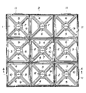
As shown in Fig.14, an installing frame in which nine
holding sections 41, 41 ... having plane round shapes are
arranged in three perpendicular and three lateral lines is
constituted in a frame 40. The above holding sections 41,
41 ... are held in the frame 40 by the surrounding
connection plates 55, 55 ... . The frame 40 is constituted
by the above connection plates 55, 55 ... and the outer
walls of outer edges, and the holding sections 41, 41
are arranged in the frame as described above.
The frame 40 of the installing frame, as described in
- 22 -
~.~8fi270
1 the above two examples, is also constituted in a plane
square having a side of 330mm, the thickness of the outer
wall is 2mm, and t~le height is 40mm. Further, the inside
diameter of the above holding sections 41, 41 ... is 106mm,
respectively.
Each of the above holding sections 41, 41 ... is
surrounded by a section surrounding wall 42 having a ring
shape. The thickness of the section surrounding walls 42,
42 ... is 2mm. Further, on the section surrounding wall 42
of the above holding sections 41, 41 ..., as shown in
Fig.14, Fig.15, Fig.17 and Fig.18, a protrusion piece 43 is
protruded from the top into an obligue downward direction of
the section, respectively. The width of the protruded
direction of the above protrusion pieces 43, 43 ... is lOmm,
and the angles between the protrusion pieces and the section
surrounding walls 42, 42 ... are about 30. As the result,
the lower edge of the protrusion pieces 43, 43 ... are
protruded in the direction of the section center in about
5mm. Further, as shown in Eig.14, Fig.15 and Fig.17, eight
notches 44, 44 ... for penetrating water at regular angles
of 45 are formed in the above protrusion pieces 43, 43 ... .
At the lower center of each of the above holding
sections 41, 41 ..., as shown in Fig.14, Fig.15 and Fig.18,
a holder 45 of each wooden brick b-3 is arranged so as to
stand up. The above holders 45, 45 are circular pedestals
which stands up in a height of about lOmm from the bottom of
the holding sections 41, 41 ... . Moreover, the upper
surface of the holders 45, 45 ... have round hollows 46, 46
... of which surrounding edges are left and the height is
about lmm. A vis hole 47 is made at the center of each of
the above round hollows 46, 46 ... so as to pass through the
upper surface and the under surface. Further, two small
joining holes 48, 48 which are arranged on a straight line
with the above vis hole 47 are made around the vis hole. As
shown in Fig.14, four arms 49, 49 .... are protruded from the
- 23 -
~ X8~3~70
1 surrounding of tile above holder 45 at regular angles of 90,
and these arms are joined to the inside of the section
surrounding wall 4~ of the holding section 41.
Moreover/ a protrusion 50 for preventing sinking of the
wooden bricks is horizontally projected around the lower
part of the above holders 45, 45 ..., at both lower sides of
the above arms 49, 49 ... and at the lower inside of the
above section surrounding walls 42, 42 ..., respectively.
Then, as shown in Fig.14, Fig.16 and Fig.17, many
elastic tubes 56, 56 ... for stepping and pressing are
provided on connection plate 55 for connecting each of the
holding sections 41, 41 to the above arrangement. The top
of the tube 56, 56 ... for stepping and pressing is
determined so as to have almost same height as the top of
the wooden bricks b-3, b-3 ... which are inserted and held
in the holding sections 41, 41 ... . In this example, the
height of the tube 56, 56 ... is 50mm from the top to the
bottom of the installing frame.
On the contrary, as shown in Fig.14, Fig.15, Fig.17 and
Fig.18, two joining projections 51, 51 are projected on each
of two adjacent sides which contain an angle and belong to
four sides of the outer walls of the above frame 40,
respectively, and corresponding joining holes 52, 52 are
made on the other two sides. The above joining projections
51, 51 on one side are formed on the outer wall which partly
overlaps on the section surrounding walls 42, 42 of the
holding sections 41, 41 situated at the corner of the frame
40. Then, as shown in Fig.15 and Fig.18, the joining
projections 51, 51 are projected from the outer wall of the
frame 40 so as to be situated slightly above the thickness
of the protrusions 50, 50 ... for preventing sinking. The
projection width is about 4mm, slightly wider than the
thickness of the outer wall, namely 2mm. The thickness in a
height direction is about 6mm. Further, as shown in Fig.14
and Fig.17, the length of the direction along the outer
- 24 -
- '
'
- - , . .
, . . .
88Z70
1 walls of the above joining projections 51, 51 ... is
determined to be about 45mm.
Moreover, the above joining holes 52, 52 of the side of
the outer wall of the frame 40 are arranged so as to
correspond to the above joining projections 51, 51, and
these holes are made on the outer wall which overlaps on the
section walls 42, 42 of the holding sections 41, 41 situated
at the corner of the frame 40. AS shown in Fig.15 and
Fig.18, the joining holes 52, 52 are made at the outer wall
of the frame 40 so as to be situated above the thickness of
the protrusions 50, 50 for preventing sinking. The height
from the lower part of the joining holes 52, 52 is slightly
above 6mm. Then, the length of the direction along the
outer walls of the above joining holes 52, 52 ... is
slightly above 45mm.
Furthermore, the above whole constitution elements are
integrally molded out of plastics which are obtained by
mixing a main polypropylene material, and a weathering agent
and the like.
In this embodiment, as the installing frame is
constituted as described above, as explained in the
following, the frame can be used by holding for the pavement
of sidewalks and the like, the wooden bricks b-3, b-3
having the plane round configuration in the holding sections
41, 41 ..... . The plane round wooden bricks b-3, b-3
having a diameter of lOOmm and a thickness of 40mm are
suitable for the holding object.
Before the installing frames are installed on sidewalks
and the like, the wooden bricks b-3, b-3 ... are inserted
and held in the holding sections 41, 41 of the installing
frames, respectively. The steps and the action and effect
which are caused by each constitution element of the
installing frame are the same as those of two examples of
the first invention.
Then, Fig.17 shows the installing frame in which the
- 25 -
~. .
, . ~ - .
.
- ~ .
~1 2~8270
1 wooden bricks b-3, b-3 ... . Fig.l~ shows a condition in
which the wooden bricks b-3, b-3 ... are inserted in the
holding sections 41, 41 ... and fixed on the holder 45, 45
... with the vis 53, 53 ... .
Further, the ground constitution of the necessary
installing zone of sidewalks and the like is the same as
that of two examples as described above.
The steps for installing the frame which holds the
wooden bricks b-3, b-3 on the ground are also identical with
those of the first example of the present invention.
The actions and effects of the installing frame are
almost identical with those of the above example of the
present invention.
Differences are as follows.
In this example, as the tubes 56, 56 ...... for stepping
and pressing are provided on the connection plates 55, 55
... between the holding sections 41, 41 ..., pedestrians can
walk and cars can run on the plates, and it is unnecessary
especially to fill up the gaps which exist between the plane
round holding sections 41, 41 ... . Further, as the tubes
56, 56 ... for stepping and pressing are passed through the
plates, rainwater and the like can be allowed to flow on the
ground.
Industrial Applicability
According to the installing frames of the present
invention, the pavement of wooden bricks can be simply and
efficiently finished by holding the wooden bricks in the
frames and then by installing the frames on the sidewalks to
be built in parks, common roads, parking places and the
like. Furthermore, the pavement by using the wooden bricks
which are finished by such a way, can be obtained a smooth
road surface, can permit the expansion and constraction of
wooden bricks, and can have good water permeability.
- 26 -