Note : Les descriptions sont présentées dans la langue officielle dans laquelle elles ont été soumises.
3508
-- 1 --
The present invention relates to a new and improved
televisions audio receiver system and is more particularly
directed to apparatus and a method for receiving and
reproducing stereo television sound.
Under present television broadcasting standards, a band
of frequencies approximately 80 KHz wide is designated
within each 6 MHz television channel for the transmission of
the audio component of a television signal. Within this
band of frequencies, an RF main audio carrier signal is
frequency modulated by an audio baseband signal for
producing a main aural audio transmission signal. The
transmitted main aural audio signal is received by a
television receiver that covers the RF audio carrler signal
to a signal having a frequency centered at 4.5 MHz. The
converted 4.5 MHz sound carrier is then processed by an FM
detector to reproduce the main aural audio signal that was
used to frequency modulate the RF audio carrier at the
transmitter.
The Federal Communications Commission has recently
approved a standard for broadcasting stereophonic television
sound. The standard approved uses the Zenith* Broadcast
Delivery System and the dbx noise-reduction system. This system
was, in part, an outgrowth of the well-known techni~ues for
* trade mark
~'J
. .
. ~. ,' . .
. . : -
: . . : . . ~ - .
. : . ' ~
transmitting stereophonic audio signals which has been
popular in radio broadcasting for some time. The
basic FCC-approved system for stereophonic radio
broadcasting is disclosed in U.S. Patent No. 3,257,511
to R. Adler, et al. In this system, the arithmetic
sum of left (L) and right (R) audio source signals
(L~R), commonly referred to as the main channel
modulation, is used to directly frequency modulats the
RF carrier signal. ~he difference between th~ left
and right stereophonically related signals (L-R) is
used to amplitude modulate a 38 KHz subcarrier signal
in a suppressed carrier fashion with the resultant
double-sideband signal being impressed as frequency
modulation on the radiated RF carrier. In addition, a
pilot subcarrier signal of 19 KHz is transmitted ~or
synchronization of the FM receiver. The FM receiver
extracts the 19 KHz pilot subcarrier, doubles its
fre~uency, and applies the resulting 38 KHz signal to
a synchronous detector where the (L-R) difference
signal is recovered ~rom the amplitude modulated 38
KHz stereophonic subcarrier. The recovered ~L-R)
modulation is then suitably matrixed with the (L+R)
main channel modulation in order to recover the
original left and right stereophonic signals.
The ~ore~oing ste eophonic radio broadcasting
system often also includes an SCA component which
allows broadcasters to provide a subscription
bac~ground music service. The SCA component comprises
a 67 KHz subcarrier frequency modulated by the
;
.
~! 2~3~508
background channel program, the fre~uency modulated
subcarrier being used to frequency modulate the main
RF carrier signal together with the stereophonic
modulation.
Various systems and apparatus have been proposed
for the transmission of stereophonic sound together
with a conventional television picture transmission.
These systems normally utilize the radio broadcasting
stereophonic transmission techniques discussed above
but with, in most cases, different subcarrier
frequencies selected for their compatibility with the
transmitted video signal. One such prior art system
i~ disclosed in U.S. Patent No. 4,048,654 to Wegn~r.
This patent discloses a transmission system in which a
composite baseband signal identical to that employed
in FM stereophonic radio broadcasting is employed to
frequ~ncy modulate the main sound carrier of a
television transmission signal. Thus, the proposed
composite baseband signal includes an (L+R) main
channel component, an amplitude modulated double-
sideband suppressed-carrier 38 KHz subcarrier (L-R)
component and a 19 KHz pilot component. In another
embodiment, the use of a subcarriar signal having a
frequency (f~l) characterizing the transmitted video
signal is pro~osed in lieu o~ the 38 K~z (L-R) channel
subcarrier to reduce interference from the video
component of the television signal.
Another system, which was proposed in U.S. Patent
No. 3,099,707 to R.B. Dome, also employed the
. : - . ~
:. , : .- ' .~ ' -
... , ~ . . ..
. : . ., -
: . - ,, :
.
.
~1.28850~3
conventional stereophonic radio broadcasting system
but with an (L-R) channel subcarrier equal to 1.5fH
and a pilot signal equal to 2.5fH. These frequencies
were selected to minimize the effect of the video
components of the television signal appearing in the
recovered sidebands of the (L-~) channel signal.
U.S. Patent No. 3,046,329 to Reesor discloses yet
another similar system in which the composite baseband
signal used to frequency modulate the main sound
carrier includes only the main channel ~L+R) component
and the upper sidebands of the (L-R) channel signal
amplitude modulated on a subcarrier having a frequency
;~ of 2fH. Other prior art systems for stereophonic
television sound transmission have proposed the use of
frequency modulated subcarriers for the (L-R) stereo
channel typically centered at 2fH, although a center
frequency of l.5fH has also been proposed.
As previously mentioned, in addition to
~ transmitting stereophonic sound components on the main
- 20 aural carrier of a transmitted television signal, it
is also desirable to transmit additional information
- thereby more completely exercising the available audio
bandwidth within a television channel. For example,
the transmission of a second audio program ("S~P")
signal woul(i enable a vie-~er to selectively operate a
television receiver for reproducing the audio signals
associated with the transmitted stereophonic
information, or alternatively, the audio signals
associated with the transmitted second audio program
:
.
. .
3~3508
which may comprise, e.g., a foreign language version
of the television program.
One prior art proposal for providing a second
language capability in connection with a transmitted
television signal is disclosed in previously mentioned
U.S. Patent No. 4,048,654 to Wegner in which the two
channels of a stereophonic-like signal are employed.
In particular, the (L+R~ main channel signal is used
to transmit a first language audio signal and the (L-
10 R) stereo channel signal is used to transmit a second
language audio signal. U.S. Patent No. 3,221,098 to
Feldman discloses a transmission system allowing for
the simultaneous broadcast of a single television
program having up to four or more different language
soundtracks by forming a composite baseband signal
consisting of four or more different subcarrier
signals each amplitude modulated with a different
p language audio signal, the composite baseband signal
being used to frequency modulate the main RF audio ~ -
carrier. Yet another proposed second language system
uses a frequency modulated subcarrier baseband signal
centered at 2fH for both stereophonic sound
transmission and for second language transmission. A
pilot signal, modulated with one of two different
frequencies, is used to indicate which service is
being broadcast.
The foregoing systems and techniques for
transmitting different audio signals in conjunction
with a standard television transmission were not
:, .. , . . ' :
- ~ ~ :. ' .,
.
~, .
1~8508
adopted in the U.S. for a number of reasons including, in
certain cases, poor performance and, in others,
incompatibility with U.S. television transmission standards.
The concept behind the Zenith stereo broadcast system
adopted in the U.S. is disclosed in U.S. Patent No.
4,405,944 to Eilers et al. This system comprises an audio
transmission system that is fully compatible with U.S.
television broadcasting standards and is capable of
providing stereophonic sound transmissions together with a
second audio program service.
In the Zenith stereo broadcast delivery system, audio
information is located in the region from about 4.4 to g.6
MHz above the video carrier of a television channel
allocation. The audio portion takes up only about 0.20 MHz,
which is small compared to the large portion of bandwidth
occupied by the video (luminance and chroma) signal. In the
past, a monophonic audio channel was transmitted as an (L+R)
FM signal with a frequency range of 50-15,000 Hz. In the
Zenith system, a pilot signal has been added at the
horizontal scanning line frequency fH(15.734) to allow new
stereo receivers to locate a second channel for stereo,
which resides from 16.47-46.47 kHz (centered at 2fH) from
the bottom of the audio allocation. This second channel is
the key to receiving stereo sound, as it is an (L-R) AM signal
* trade mark
~'
. ' ~ ' ' ' " ' ' ' ,' ~ ,', ~ '
5~
with the same frequency range as the mono channel.
Stereo i5 achieved when the L-R and L+R signals are
combined.
A third channel, the second audio program or
"SAP", is provided in the Zenith system for bilingual
programming and other commentary. The SAP channel is
FM and extends from about 65 to 95 kHz (centered at
5fH) with a frequency range of 50 Hz to 12 kHz.
Professional channels which may be used for voice or
data can be inserted into the remaining audio space of
about 98.2 kHz to 106.5 kHz (centered at 6.5fH).
Several types of sound channel processing for these
audio signals at the home televisiojn receiver are
known O
. One such processing technique is provided by a
"separate aural carrier receiver", in which the aural
carrier is processed separate from the visual carrier.
Since the aural carrier is transmitted without
incidental phase modulation ("ICPM"), none can reach
the FM detector so that this receiver can be free of
all video related buzz.
A second known receiver Eor television sound
channel processing is referred to as the "split sound
receiver". This method of sound processing was used
in the early days oE television be~ore intercarrier
detection was introduced. The video and sound
portions of a received television signal are down
converted to a lower frequency and the sound component
of the composite signal is pulled off and processed to
.' . ' . , ' ' ': ' ~ ' ' ~ '
~.~88S0~3
provide an audio output~ In the split sound receiver
technique, tuner-introduced ICPM can cause low
frequency noise in the sound output.
~either separate aural carrier receiver technigues
nor split sound receiver techniques can be used in a
cable television environment due to the high FM noise
in the oscillators used to down convert the television
- signal. Expensive oscillators with separate tuning
systems would be required to overcome this problem,
and thus the techniques are not economically viable in
cable television systems.
A third known type of sound channel processing is
referred to as the nquasi-split sound receiver". In
this technique, separate processing of the sound and
video signals is used, but with synchronous detection
combined with intercarrier sound detection. Such a
receiver is disclosed in U.S. Patent No. 4,405,944
referred to above. Nyquist ICPM is eliminated in the
quasi-split sound receiver by a specially designed IF
filter with symmetrical response centered at the video
carrier. Although this type of receiver is relatively
immune to tuner-introduced ICPM, microphonics, local
oscillator phase noise, reverse mixer feedthrough to
the tuner of local oscillator, and to video related
frequency modulation c~used hy the AF~/~FT circuits,
it suffers froln distortion caused by inter~ering
harmonics oE the television horizontal line frequency.
Such harmonics fall within the pilot signal, the (L-R)
subchannel and the SAP signals~
~ .
. .
: : ,,, : . :. , ~ .
~, -
. : , . , . . . :
: .
. , - .
:' ' . ~ .
~.2~38S08
- It would be advantageous to provide an apparatus
and method for receiving stereo broadcast television
sound which avoids such interference. Such an
apparatus and method should be able to be used in the
cable television environment and remain uneffected by
harmonics of the television horizontal line frequency,
as well as phase noise due to jitter in the cable
television converter and local oscillator tuning loop.
The present invention provides an apparatus and
method with these advantages, through the use of two
separate receivers for the (L+R) signal and the pilot,
(L-R), and SAP signals. The result is a substantially
improved quality of television stereo sound reception.
: '
' ,
", . .
: ' ' '
~.288~0~3
-- 10
In accordance with the present invention, an apparatus
and method are provided for receiving and reproducing
stereo television sound. A transmitted television signal
includes an audio component comprising a main carrier
signal frequency modulated in accordance with the composite
modulation function. In support of one embodiment of the
invention, this function has a first component comprising
the sum of first and second stereophonically related audio
signals, and a second component comprising a first
subcarrier having a frequency 2fH modulated by the
difference between said stereophonically related audio
signals~ The frequency fH is the horizontal scanning line
frequency associated with the horizontal synchronization
signal of the transmitted television signal.
The apparatus comprises input means responsive to the
transmitted television signal for developing a first signal
corresponding to the composite modulation function.
Intercarrier detector means are coupled to receive the first
signal for detecting the portion thereof corresponding to
the first component of the composite modulation function
and producing a first audio output signal comprising the
sum of the stereophonically related audio siqnals.
Independent FM detector means are coupled to receive the
first signal for detecting the portion thereof corresponding
to the second component of the composite modulation
~ . ,
.... ' :- -'- ~ ~ . , ' : :
: . .
.... - . . .
-
~ ~3~5()8
function and producing a second audio output signal
comprising the difference of the stereophonically rela~ed
audio signals. Means are coupled to receive the first and
second audio output signals for producing therefrom a first
S channel audi.o output and a second channel audio output.
In one preferred embodiment, the apparatus further
includes means coupled to the input means for converting the
first signal to a first intermed:Late frequency for input to
the intercarrier detector, and for converting the first
signal to a second intermediate freguency for input to the
independent FM detector means.
- The composite modulation function can include a third
component comprising a second subcarrier having a frequency
5fH modulated in accordance with a third audio signal. The
independent FM detector means can then be used to
selectively detect the portion of the first signal
corresponding to the third component and produce a third
audio output signal therefrom.
At least one of the first and second audio output
signals can be delayed to provide equalization
therebetween. Such delay enables the first channel audio
.:
output and second channel audio output to be in proper
phase.
According to another aspect of the invention, there is
provided apparatus for receiving and reproducing stereo
- - ;~
- ~ : . ' ',' , ' ' : . : -
,. ,~ . .
~ Z8~35(:~8
- lla
television sound characterized by a transmitted audio signal
comprising a main carrier signal, frequency modulated in
accordance with a composite modulation function having a
first component comprising the sum of first and second
stereophonically related audio signals, and a second
component comprising a first subcarrier having a frequency
2fH modulated by the difference between said
stereophonically related audio signals, where fH is the
horizontal scanning line frequency associated wit.h the
horizontal synchronization signal of a transmitted
television signal, said apparatus comprising: tuner means
. for receiving a transmitted television signal including said
audio signal; frequency converter means coupled to said
tuner means for converting the received audio signal to a
first sound carrier centered at a first intermediate
frequency and a second sound carrier centered at a second
intermediate frequency; first detector means coupled to
receive said first sound carrier for producing a first audio
output signal corresponding to one component of said
composite modulation function; and second detector means
coupled to receive said second sound carrier for producing a
second audio output signal corresponding to another
component of said composite modulation function.
~J
- : . - ' . ': - ' ' ' ' ' : -
; , .
~.~885~8
- 12
According -to a further aspect of the invention, a
method for providing reception and reproduction of stereo
sound in a television signal comprises the steps of tuning
to a transmitted television signal that contains an audio
component comprising a main carrier signal, frequency
modulated in accordance with a composite modulation function
having a first component based on stereophonic audio
signals, and a second component in a different frequency
range than said first component and based on other, related
stereophonic audio signals; converting the audio component
of said television signal to produce a first sound carrier
centered at a first intermediate frequency and a second
sound carrier centered at a second intermediate frequency;
detecting the first component of said composite modulation
function from the first sound carrier at the first
intermediate frequency; detecting the second component of
said composite modulation function from the second sound
carrier at the second intermediate frequency; and producing
from the detected first and second components a left channel
audio output and a right channel audio output.
In the drawings,
Figure 1 is a graphic representation of the frequency
spectrum of the composite baseband audio signal which is
part of a transmitted television signal; and
Figure 2 is a functional block diagram of the receiver
apparatus of the present invention.
~'I '
.
.
,. ' ~
85()8
13
Referring now to the drawings, Figure 1 i9 a
graphical representation of the multichannel sound
baseband signal 10 approved for use in television
broadcast signals. The baseband signal includes a
main channel component 12 occupying a band which
extends from 50 Hz-15 KHz. The main channel is
modulated by the left channel plus right channel (L+R)
audio. A subcarrier stereo subchannel 16 centered at ~-
twice the television horizontal scanning frequency fH
of 15.734 KHz is suppressed carrier amplitude
~modulated by the left minus right ~L-R) audio
channels. A second audio program channel 18 is
provided at 5fH. A pilot subcarrier is inserted at
the horizontal scanning frequency fH. The pilot
signal is used in prior art receivers to facilitate
recovery of the (L-R) subcarrier by synchronization of
the FM receiver. In such prior art receivers, the
pilot signal at fH is extracted, doubled, and applied
to a synchronous detector where the (L-R) difference
signal is recovered from the amplitude modulated
subcarrier at 2fH. This technique, which uses the
intercarrier detector also used to detect the ~L+R) ~
signal, is prone to intercarrier phase modulation `~;
whereby video in~ormation is detected by the sound ~`
detector. Such video information interferes with the
pilot and subcarrier areas at fH, 2fh~ etc.
The present invention overcomes this problem by
- using intercarrier detection to arrive at the (L+R)
signal together with an independent FM detector, not
" ,
",'`:
:. , , . : . - , ,." - . . .: -: : , ~ : .- ., . : . , . :
~8~
14
phase locked to the video signal, for receiving the
pilot, the (L-R), and the SAP signals. In such
manner, harmonics of the television horizontal line
frequency are avoided. The desired output of the
independent FM detector is of a higher frequency than
that o~ the intercarrier detector, where phase noise
due to jitter in a cable television converter and
local oscillator tuning loops is minimal.
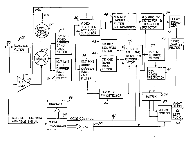
Figure 2 illustrates a cable television stereo
sound adapter for reproducing stereophonic sound
transmissions in accordance with the present
invention. Those skilled in the art will appreciate
that the teachings of the present invention can be
used to receive stereophonic sound from direct
broadcast television signals as well as over cable
television systems. The television signal containing
the composite modulation function illustrated in
Figure 1 is received at terminal 20 which is coupled
to a bandpass filter 22 and a microprocessor 66. The
signal input at terminal 20 can include data, e.g.!
from a cable television remote control, that is used
by microprocessor 66 to execute various functions
selected by a user. For example, a user can select to
receive the main stereophonic signal or the alternate
SAP channel, and microprocessor 66 will output a
signal on line 67 to execute the user's choice.
Remote control of the sound volume is accomplished via
a digital to analog converter 70 ~hat is accessed by
microprocessor 66 to control a volume control circuit
: ' ' . .: . . ~,
, .: . . ! ., ' '
. . ' ' . ' ~ ' ' .
, ' : , . . . , ' ''' ', ,
5~3~
60. A display 68 associated with microprocessor 66 is
provided to give a user visual Eeedback as to the
selections made via the remote control.
Bandpass filter 22 is used to separate the video
and multichannel sound RF signals from any other
signals (such as the data signals referred to above)
present at input terminal 20. The video and
multichannel sound RF signal is passed from bandpass
filter 22 to an RF amplifier 24. The amplified RF
signal is then coupled to a mixer 26 which, in
combination with local oscillator 28, converts the
frequency of the amplified RF signal to a new
- nintermediate" frequency. If, for example, the signal
output from RF amplifier 24 contains components at
41.25 and 45.75 MHz, and local oscillator 28 runs at
30.55 MHz, the signal output from mixer 26 will
contain frequency components at 15.2 MHz and 10.7 MHz.
The output from mixer 26 is input to a bandpass
filter 32 with a center frequency of 15.2 MHz (video
carrier) and a bandpass filter 34 with a center
- frequency at 10.7 MHz (audio carrier). Bandpass
filter 32 can, for example, comprise a simple L-C
filter while bandpass filter 34 is preferably a
ceramic filter.
The output oE bandpass filter 32 is input to a
video detector 30, which also includes an automatic
frequency control ("AFC'I) and automatic gain control
(nAGC") detector. The AFC and AGC signals are applied
to local oscillator 28 and RF amplifier 24,
-: . .. :. . : . - :
~: , . - :
,
'' ' ' .' . .'' '~ .
~1!.2~385()8
1~
respectively. Video detector 30 also receives ~he
output of bandpass filter 34. The resulting output
from detector 30 contains the main channel component
12 of the audio carrier signal having a center
fr~quency of at 4.5 MH~ (15.2 MHz-10.7 MHz). The
converted 4.5 M~z sound carrier is then processed by
an FM detector 48, after being filtered by a 4.5 MHz
bandpass filter 46, to reproduce the (L+R) audio
signal that was used to,frequency modulate the audio
carrier at the television signal transmitter.
The output from FM detector 48 is input to a
delay equalizer 56 that provides equalization between
the lL+R) signal and the (~-R) signal that is
retrieved by a separate independent FM detector as
described bellow. After the (L+R) signal is delayed by
an appropriate time period, it is passed through a 15
KHz low pass filter to limit the signal to the audio
frequencies to be ultimately reproduced. This signal
is then input to a conventional matrix 54 that
combines it with the (L-R) signal to reproduce a right
channel audio signal at terminal 62 and a left channel
audio signal at terminal 64.
In order to recover the pilot, (L-~), and SAP
signals, the output of bandpass filter 3~ is passed
through a second (preferably ceramic) bandpass f ilter
36 that provides additional filtering for high
fidelity sound reproduction. The output of filter 36
is input to a 10.7 MHz FM detector 38, that recovers
the (L-R) and SAP components 16 and 18, respectively,
. . . . : .- : ~ ..... . : . .
350~3
17
illustrated in Figure 1. The detected signal is
passed to a demodulator 40 that selectively
demodulates the AM (L-R) signa} at 31.5 KHz (2fH) or
the FM SAP signal at 78 KHz (5fH). Demodulator 40
utilizes a 50 KHz low pass filter 42 for dsmodulating
the (L-R) component or, alternately, a 78 KHz bandpass
filter 44 to demodulate the SAP component. Selection
of the component to be demodulated is made via a mode
control signal outputted by microprocessor 66 on line
67.
The demodulated output from demodulator 40 is
input to a 15 KHz low pass filter 50 that limits the
signal to the band of audio frequencies to be
reproduced. The signal is then input to a s~andard
dbx noise reduction circuit 52 and passed to matrix 54
where the (L-R) signal is combined with the (L+R)
signal to produce the desired right and let audio
channels.
It will now be appreciated that the present
invention provides reproduction of stereo broadcast
television sound without distortion due to video
information interfering with the pilot signal, (L-R)
subcarrier, and SAP subcarrier components of the
multichannel sound baseband signal. In accordance
~ith the present invention, the best (L+R) channel
performance is achieved using a quasi-parallel
intercarrier detector. Improved (L-R) channel and SAP
channel performance is achieved by using a separate
sound detector instead of the same intercarrier
: - . - : .
'.: ~ ~: : ' : . .
so~
18
detector used for recovering the (L+R) component. In
this manner, interfering har~onics of the television
horizontal line frequency with vertical scan frequency
sidebands that fall within the pilot, the (L-R)
subchannel, and the SAP signals are prevented from
distorting the stereo audio or SAP output. By using
the higher freguency components only of the separate
FM detector, where phase noise due to jitter is
minimal, and recovering the (L+R) channel using a
standard intercarrier detector at lower frequencies
(where phase noise would be severe), the quality of
television stereo sound reception is greatly improved.