Note : Les descriptions sont présentées dans la langue officielle dans laquelle elles ont été soumises.
~38~
The present inven-tlon relates to a pressure reduc-
ing valve which is mounted on a piping sys-tem for vapor
or compressed air to malntain a secondary fluid pressure
at a constant set pressure, and more particularly, to an
arrangement of the type in which a primary fluid pressure
is exer-ted on the upper surface of a piston through a pilot
valve which is opened and closed by detecting a secondary
pressure, and the pis-ton is operated according to a pressure
difference between it and the surface of a piston in com-
munication with the secondary side to open and close a main
valve connected to the piston, wherein a clearance is formed
between the upper end surface of the piston and the inner
wall surface of a body opposed to said upper end surface.
A problem with known pilot type pressure reducing
valves is that high pressure caused by primary vapor and
low operating pressures of the valve results in the produc-
tion of shocks and noises in the valve and deformation inthe surface of the piston as well as bending and breakage
of the piston rod and fur-ther damaging to the valve body
and valve seat surface.
It is therefore a technical task and feature of
the present invention to reduce the shock even if the
chattering occurs, and to rr.inimize the damage given to
movable parts around the piston.
The technical means of the present invention
employed for solving the aforementioned technical task
resicles in a pilot type pressure reduc:ing valve in which
a main valve hody and a main valve seat are operated to
be opened and closed by regulating an operating pressure
of a piston through a pi.lot valve which is operative to
detect a secondary pressure, characterized in that in a
s-tate ~here:irl the main valve body is in contact with the
main valve seat, a clearance between an upper end surface
of the piston and an inner wall surface of a body opposed
to said surface is set to zero or to close -to zero.
-- 1 --
~2~iS~
Even if a remarkable shock occurs in a piston
portion due to a chat-tering phenomenon, :its shock Eorce
i.s small because a posslble moving amount of the piston
is very small. In addition, since -the moving amount of
the piston is small even when moving down, therefore
kinetic energy is small and the impac-t force applied to
-the main valve body is also very small.
According to a further broad aspect of the present
invention, there is provided a pilot type pressure reducing
valve in which a main valve body at a main valve seat are
operated to be opened and c]osed by reyulating an operating
pressure of the piston through a pilot valve which is
operable to detect a secondary pressure, wherein in a
state where the main valve body is in contact with the main
valve seat. A clearance is provided between an upper end
surface of the piston and an inner wal]. surface of a body
opposed to the first mentioned surface, is set to zero or
-to close to zero or set to 0 to 1 mm.
FIG. 1 is a sectional view of a piston portion
of a pressure reduclng valve showing an embodiment of the
present invention; and
FIG. 2 is a sectional view of a conventional
pressure reducing valve.
Generally, in a conventional pilot type pressure
reducing valve, a clearance Xl between an upper end surEace
101 of a piston 20 and an inner wall surface 102 of a body
is maintained to be more or less 10 mm, as shown in FIG.
2.
The pressure reducing valve shown in FIG. 2
comprises a pressure reducing valve portion 1, a steam
separator 2 and a drain valve portion 3. A body 10 is
formed with an inlet 12, a valve port 1~ and an outlet 16.
The inlet is connec-ted to a primary high pressure fluid
source, and the outlet is connected to a secondary low
pressure zone. The valve port is formed by a valve seat
member.
.
.
~2~
A main valve body 18 is arranged on an inlet side
end of a valve seat 15 forminy the valve port 1~ so -that
the main valve bocly 18 may be resiliently urged by a coil
spring. A piston 20 is sli.dab].y arranged wi-thin a cylinder
22, and a piston rod 17 is placed in abutmen-t wi-th a central
pro~ectiny rod 13 of the main valve body 18 within the valve
post 14. The lower surface of the pi.ston and the piston
rod 17 are connected substantially at a hemispherical
sur~ace. A pilot valve 26 is arranyed in an upper space
between the inlet 12 and the piston 20, -that is, in a
primary pressure passage 24 in communication with a piston
chamber. A diaphragm 28is;mounted with its outer peripheral
- 2a-
:, .
edge held between flanges 30 and 32. A lower space of the
cliaphragm 28 is communicated wi.th the outlet 16 through
a secondary pressure passage 34. A head end o~ a valve
stem 36 of the pilot valve 26 is placed in abutment wi-th
a central lower surface of -the diaphragm 28, and a pressure
setting sprlng 40 for setting pressure is placed in abutmen-t
with the upper surface o:E -the diaphragm 28 -through a spring
seat 38. An adjusting screw '14 is mounted on the body 10
by a threaded connection.
When the adjus-ting screw 44 is turned to the left
or the right, a resi.lient force for depressing the diaphragm
28 of the pressure setting spring 40, is varied. Using
the resilient force of the pressure setting spring as a
reference value/ the diaphragm 28 curves in response to
the secondary pressure acting on the lower surface thereof
to displace -the valve stem 36 so that the pilot valve 26
may be opened and closed. As the result, the primary fluid
pressure is introduced into the piston chamber whereby the
piston 20 is driven, the main valve body 18 is displaced,
and the fluid of the inlet 12 flows into the outlet 16
through the valve port 14. This is automatically operated
so that when the secondary fluid pressure lowers, the valve
port 14 opens whereas when it rises, the valve port closes.
Below the valve port 14 is mounted a cylindrical
diaphragm member 46, and an annular space 48 is :Eormed
between the diaphragm member 46 and the body 10 surrounding
it, whose upper portion is communicated with the inlet 12
-through a cone-shaped screen S0 whereas the lower portion
is communici~ted with the upper port:ion of a drain valve
chamber 52. The upper porti.on of the drain valve chamber
52 is communicated with the valve port 14 throu~h a central
opening o:E the diaphragm member 46. A swirl vane 54 is
formed with an inclined wall which is disposed in the
annular space 48.
-- 3 --
Accordingly, the :Eluid from the inlet 12 is curved
or angula-ted in its -travel by the swirl vane 5~ and swirled
when the valve port 14 ls opened to cause the fluid -to pass
through the annular space ~8. The liquid is moved outside
into impingement on the inner wall oE the body and -there-
around and flows down in-to the drain valve chamber 52, while
light gas swirls in the cen-tral portion, passes from the
central opening of the diaphragm member 46 toward the valve
port 1~ and runs away toward the outlet 16.
The drain valve chamber 52 is formed with a drain
valve port 58 leading to a drain port 56. ~ spherical valve
floa-t 60 is covered with a float cover 62 and is dis-
placeable therein. A vent hole 64 is formed in the upperportion o the float cover 62.
Accordingly, the valve float 60 moves up and down
according to a water level of the drain valve chamber 52
to open and close the drain valve port 58 to automatically
discharge water staying in the drain valve chamber 52.
In the pressure reducing valve constructed as
men-tioned above, when the set pressure (secondary pressure)
is lower than the primary pressure, that islthe reduction
ratio is great, a remarkable chattering phenomenon occurs.
This reduction ratio is in the case, for example, where
the primary pressure 1.0 kg/cm2 is reduced to -the set pres-
sure 2 kg/cm2 or less.
According to experiments, in the pressure reducing
valve shown in FIG. 2, when pressure is graduaJ.ly lowered
from a state wherein the diaphragm 28 i.s not urged by the
pressure setting spring ~0 to a state wherein it is urged,
the pilot valve 26 star-ts to open. However, in the case
where at that time the primary pressure is 10 kg/cm2 and
the secondary pressure is atmospheric pressure, that is
at the time of star-t, a high pressure primary vapor rapidly
flows into the upper space of the piston 20 through the
pilot valve 2~, and the valve po.rt 1~ rapidly opens. At that-time,
a portion in the vicinity of the secondary side of the valve port is
momentarily at high pressure, and therefore the pilot valve opens and
at the same time the valve-por-t rapidly
closes. However, since -the secondary pressure is low,
pressure in the vicinity of the outlet momentarily becomes
lowered and therefore the pilot valve rapidly opens. This
procedure is r~ea~edlylr carried out to produce great shocks
and noises.
This results from the fac-t that the piston 20
is forced upward by the jet flow of high pressure fluid
flowing toward the secondary upon the rapid opening of the
main valve body 18 and impactly impinges upon the inner
wall surface of the body opposed to the upper end surface
of the piston 20, and when moving down, the piston rod 17
again impinges upon the main valve body 18. This results in
occurance of problems, such as, deformation of the upper
end surface of the piston 20, bending and breakage of the
piston rod 17, and damages to the main valve body 18 and
the valve sea-t surface of the main valve seat 15.
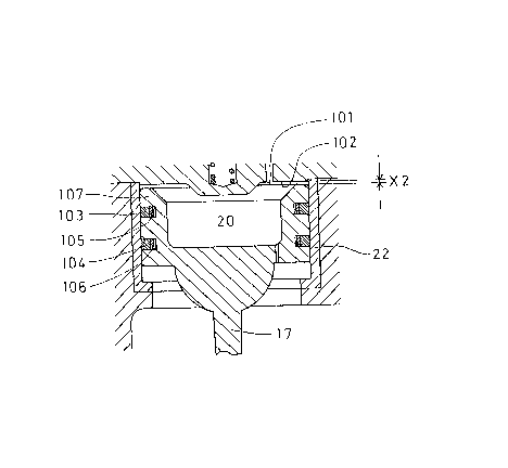
Fig. 1 shows the state in which a valve,port 1~
is closed. A clearance X2 between an upper end surface
101 of a piston and an inner wall surface of a body is very
small as shown in FIG. 2. In actual fabrication, the clear-
cance is set to approximately 0.5 mm in consideration of
working to].erance. Most preferably, the clearance is close
to zero, of course.
Annular grooves are provided in -the circumferen-
tial wall of the piston 20, and piston rings 103, 104, made
of Eluororesin are disposed in these grooves. Resilien-t
members 105, 106 are disposed in the grooves and extended
from the inside to the outside to enhance the slidability
and sealing properties rela-tive to the cylinder 22.
In the prior art, since the clearance X2 is large,
the impact force -that the piston impinges upon the inner
wall surface 102 of the body is great, and a peripheral
portion 107 of the upper end of the piston is deformed down-
ward to compress the piston ring 103, thus deteriorating
the sealing properties and slidabili-ty thereof. However,
according to this improvement, since the clearance X2 is
small, the aforesaid phenomenon will not occur, and a smooth
~2~
functionlng con-tlnues for a lony perlod of tlme.
Accordingly, even if -the chatteriny should occur,
vibration noises are small, and a quiet operating sta-te
ls malntalned without damaging -the pis-ton rod and the end
surface of the piston. In addi-t:ion, since the valve seat
surface ls not damayed, the characterlstlcs peculiar to
the pressure reducing valve, such as pressure characteri-
stic, shutoff boosting, and the llke, are achieved.
-- 6
,.
. . ~ . .
, .