Sélection de la langue

Search

Sommaire du brevet 1289163 

Énoncé de désistement de responsabilité concernant l'information provenant de tiers

Une partie des informations de ce site Web a été fournie par des sources externes. Le gouvernement du Canada n'assume aucune responsabilité concernant la précision, l'actualité ou la fiabilité des informations fournies par les sources externes. Les utilisateurs qui désirent employer cette information devraient consulter directement la source des informations. Le contenu fourni par les sources externes n'est pas assujetti aux exigences sur les langues officielles, la protection des renseignements personnels et l'accessibilité.

Disponibilité de l'Abrégé et des Revendications

L'apparition de différences dans le texte et l'image des Revendications et de l'Abrégé dépend du moment auquel le document est publié. Les textes des Revendications et de l'Abrégé sont affichés :

  • lorsque la demande peut être examinée par le public;
  • lorsque le brevet est émis (délivrance).
(12) Brevet: (11) CA 1289163
(21) Numéro de la demande: 1289163
(54) Titre français: BEC ORIENTABLE DE ROBINET
(54) Titre anglais: PIVOTING FAUCET NOZZLE
Statut: Périmé et au-delà du délai pour l’annulation
Données bibliographiques
(51) Classification internationale des brevets (CIB):
  • F16L 27/00 (2006.01)
  • E03C 01/08 (2006.01)
  • F16L 27/08 (2006.01)
(72) Inventeurs :
  • WATSON, J. CHARLES (Canada)
  • COX, MONICA (Canada)
(73) Titulaires :
  • WALTEC INC.
(71) Demandeurs :
  • WALTEC INC. (Canada)
(74) Agent: SMART & BIGGAR LP
(74) Co-agent:
(45) Délivré: 1991-09-17
(22) Date de dépôt: 1988-11-28
Licence disponible: S.O.
Cédé au domaine public: S.O.
(25) Langue des documents déposés: Anglais

Traité de coopération en matière de brevets (PCT): Non

(30) Données de priorité de la demande: S.O.

Abrégés

Abrégé anglais


72582-8
ABSTRACT
Disclosed is a pivoting faucet nozzle assembly
comprising a body member having a first circular passageway
adapted to receive an end portion of an inlet tube and a second
passageway comprising an outlet communicating with the first
opening. The second passageway has a shoulder disposed a
predetermined distance from a central axis of the first
passageway. The end of the tube has a longitudinally extending
tab which engages with the shoulder upon pivoting of the body
member to either of two angular limits, e.g. 45°, from a central
position in which the tab is substantially centered in the second
passageway. The nozzle can be pivoted enough to rinse the walls
of a sink but not enough to spray water on the counter top in
which the sink is mounted.

Revendications

Note : Les revendications sont présentées dans la langue officielle dans laquelle elles ont été soumises.


THE EMBODIMENTS OF THE INVENTION IN WHICH AN EXCLUSIVE
PROPERTY OR PRIVILEGE IS CLAIMED ARE DEFINED AS FOLLOWS:
1. A pivoting faucet nozzle assembly comprising a body
member having a first circular passageway extending from an
exterior surface region of said body a first predetermined
distance into said body, said first passageway receiving an outlet
portion of a supply tube and said body having a second passageway
extending from a different exterior surface region of said body a
second predetermined distance into said body, said second
passageway intersecting said first passageway, said second
passageway having a shoulder disposed a predetermined distance
from a central axis of said first passageway, said distance being
less than the radius of said first passageway, said end of said
tube having a longitudinally extending tab which extends into said
second passageway and engages with said shoulder upon pivoting of
said body member to either of two angular limits from a central
position in which said tab is substantially centered in said
second passageway, said assembly including means to retain said
body member against longitudinal movement on said outlet tube
while permitting rotational movement and means providing a seal
between said tube and said body member.
2. An assembly as claimed in claim 1 wherein said end
portion of said tube has a first external groove adapted to
receive an O-ring to provide a seal with said body member.
3. An assembly as claimed in claim 2 wherein said end

portion of said tube has a second external groove adapted to
receive an end of a screw through said body member whereby said
body member is retained in position longitudinally of said inlet
tube.
4. An assembly as claimed in claim 3 wherein said body
member is pivotable about 45° either side of said central
position.
5. An assembly as claimed in claim 4 wherein said second
passageway extends substantially at right angles to said first
passageway.

Description

Note : Les descriptions sont présentées dans la langue officielle dans laquelle elles ont été soumises.

This in~ention relates to a pivoting nozzle faucet
assembly.
U.S. patent No. 3,841,346 of Robert Amblank, issued
October 15, 1974, discloses a pivotable water outlet which can
direct water into either a tub or a shower. When directing water
into the tub, the nozzle can be pivoted through a limited range.
The amount of pivoting is controlled by a stop screw which extends
through a housing wall into a limiting groove in an outflow sleeve
to which the nozzle is attached.
U.S. patent No. 2,878,059 of H.A. Limle, issued
~larch 17, 1959, discloses a modified faucet which can be turned
from a normal down position to a straight up position to act as a
fountain. It is not adapted to be pivoted during use.
U.S. patent No. 2,790,632 of C.W. Mellette, issued
April 30, 1957, discloses a spout with an adjustable discharge
head which incorporates a valve mechanism to control the discharge
of water. If tilted past certain limits, no water flows; if
turned straight up, there is a reduced flow of water.
U.S. patent No. 2,570,635 of O.F. Beyer, Jr., issued
October 9, 1951, discloses a spout with a nozzle that can be
freely rotated through 360 to direct water up or down.
U.S. patent No. 1,217,512 of P.F. Silberman, issued
February 27, 1917, discloses a faucet attachment or fixture which
has a soap container which connects to hot and could water
faucets. The container can turn about a horizontal axis. No
mechanism is provided to limit the amount of turning.
U.S. patent No. 904,673 of W.E. Bideker, issued

3~i3
November 24, 1908, discloses a rotatable nozzle tip for fire
hoses.
The present invention provides a novel pivoting faucet
nozzle assemhly with a discharge head that can be pivoted side to
side within limits, e.g. 45 either side. This facilitates
rinsing out a sink while aYoiding spraying water on to the counter
top.
Thus, in accordance with a broad aspect of the
invention, there is provided a pivoting faucet nozzle assembly
comprising a body member having a first circular passageway
extending from an ex~erior surface region of said body a first
predetermined distance lnto said body, said first passageway
receiving an outlet portion of a supply tube and said body having
a second passageway extending from a different exterior surface
region of said body a second predetermined distance into said
body, said second passageway intersectiny said first passageway,
said second passageway having a shoulder disposed a predetermined
` distance from a central axis of said first passageway, said
distance being less than the xadius of said first passageway, said
end of said tube having a longitudinally extending tab which
extends inko said second passageway and engages with said shoulder
upon pivoting of said body member to either of two angular limits
from a central position in which said tab is substantially
centered in said second passageway, said assembly including means
to retain said body member against longitudinal movement on said
outlet tube while permitting rotational movement and means
providing a seal between said tube and said body member.
B

~Z8~
A preferred embodiment of the invention will now be
described in conjunction with the accompanying drawings, in which:
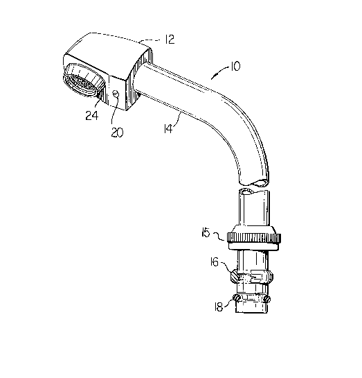
Figure 1 is a perspective view of a pivoting faucet
nozzle assembly according to the invention,
Figure 2 is an isometric~ view of an end portion of the
inlet tube of tha assembly, and
Figure 3 is a cross sectional isometric view
2a
: B
.

63
of the nozzle and part of the inlet tube.
Referring to Figure 1~ the faucet assembly 10 comprises
a nozzle or head portion 12 attached to one end of an inlet tube
lg. The other end of the inlet tube 14 is adapted to be attached
to a water supply pipe (not shown) where a retaining nut 15
presses a split plastic ring 16 against the end of the pipe. A
resilient 0-ring 18 forms a seal with the pipe in well known
manner. The inlet tube can be rotated about a vertical axis.
The nozzle 12 is secured against longitudinal movement
on tube 14 by a screw 20, the tip of which fits in groove 22
(Figure 2) of tube 14. The screw 20 does not, however, engage the
bottom of groove 22 which would interfere with pivoting movement
of nozzle 12.
; Figure 1 shows the nozzle as being provided with an
aerator and filter screen 24 but this is not essential.
Referring to Figure 2 again, it is seen that the end
portion of tube 14 has a second groove 27. Groove 27 is provided
with a resilient 0-ring 30 which forms a seal with the nozzle
while allowing the nozzle to pivot on the tube 14. The end of
tube 14 is provided wikh a longitudinally extendin~ tab 32 which
limits the amount of pivoting of the nozzle 12, as will be
explained in connection with Figure 3.
Referring to Figure 3, the nozzle or body member 12 has
a first circular passageway 35 adapted to receive an end portion
36 of inlet tube 14 (only part of which is shown). ~ second
passageway 36, comprising a fluid outlet, communicates with the
first passageway 35. The second passageway has a shoulder 40

disposed a predetermined distance from a central axis 41 of the
first passageway, the distance being less than the radius of the
first passageway 35. In the position shown in Figure 3, the tab
32 is centered in the seconcl passageway 36. Howeverr if the
nozzle 12 is pivoted sufficiently, the tab 32 will engaye with
shoulder 40 ~o preven~ further pivoting.
The outlet opening 43 is provided with threads, not
numbered, to receive an aerator and filter screen assembly.
The passageways in the nozzle, which are preferably at
right angles to one another, can be easily provided by machining,
as will be understood by those skilled in the art. For example,
the second passageway 36 can be formed first and a first part of
it enlarged to form the shoulder 40. The first passageway 35 can
then be formed which results in cutting away part of the shoulder
up to a plane through the end 50 of the shoulder. The lower end
of the second passageway can then be enlaryed to provide the
opening 43 for the aerator and filter screen assembly.
The end 50 of the shoulder 40 limits the extent to which
the nozzle can be pushed on to the tube 14.
. .~ . 1
.s -

Dessin représentatif
Une figure unique qui représente un dessin illustrant l'invention.
États administratifs

2024-08-01 : Dans le cadre de la transition vers les Brevets de nouvelle génération (BNG), la base de données sur les brevets canadiens (BDBC) contient désormais un Historique d'événement plus détaillé, qui reproduit le Journal des événements de notre nouvelle solution interne.

Veuillez noter que les événements débutant par « Inactive : » se réfèrent à des événements qui ne sont plus utilisés dans notre nouvelle solution interne.

Pour une meilleure compréhension de l'état de la demande ou brevet qui figure sur cette page, la rubrique Mise en garde , et les descriptions de Brevet , Historique d'événement , Taxes périodiques et Historique des paiements devraient être consultées.

Historique d'événement

Description Date
Inactive : CIB de MCD 2006-03-11
Le délai pour l'annulation est expiré 1997-09-17
Lettre envoyée 1996-09-17
Accordé par délivrance 1991-09-17

Historique d'abandonnement

Il n'y a pas d'historique d'abandonnement

Titulaires au dossier

Les titulaires actuels et antérieures au dossier sont affichés en ordre alphabétique.

Titulaires actuels au dossier
WALTEC INC.
Titulaires antérieures au dossier
J. CHARLES WATSON
MONICA COX
Les propriétaires antérieurs qui ne figurent pas dans la liste des « Propriétaires au dossier » apparaîtront dans d'autres documents au dossier.
Documents

Pour visionner les fichiers sélectionnés, entrer le code reCAPTCHA :


Pour visualiser une image, cliquer sur un lien dans la colonne description du document. Pour télécharger l'image (les images), cliquer l'une ou plusieurs cases à cocher dans la première colonne et ensuite cliquer sur le bouton "Télécharger sélection en format PDF (archive Zip)" ou le bouton "Télécharger sélection (en un fichier PDF fusionné)".

Liste des documents de brevet publiés et non publiés sur la BDBC .

Si vous avez des difficultés à accéder au contenu, veuillez communiquer avec le Centre de services à la clientèle au 1-866-997-1936, ou envoyer un courriel au Centre de service à la clientèle de l'OPIC.


Description du
Document 
Date
(aaaa-mm-jj) 
Nombre de pages   Taille de l'image (Ko) 
Abrégé 1993-10-21 1 16
Revendications 1993-10-21 2 48
Dessins 1993-10-21 1 34
Description 1993-10-21 5 135
Dessin représentatif 2001-07-18 1 13
Taxes 1994-09-14 1 52
Taxes 1995-08-28 1 36
Taxes 1993-09-13 1 32