Sélection de la langue

Search

Sommaire du brevet 1289171 

Énoncé de désistement de responsabilité concernant l'information provenant de tiers

Une partie des informations de ce site Web a été fournie par des sources externes. Le gouvernement du Canada n'assume aucune responsabilité concernant la précision, l'actualité ou la fiabilité des informations fournies par les sources externes. Les utilisateurs qui désirent employer cette information devraient consulter directement la source des informations. Le contenu fourni par les sources externes n'est pas assujetti aux exigences sur les langues officielles, la protection des renseignements personnels et l'accessibilité.

Disponibilité de l'Abrégé et des Revendications

L'apparition de différences dans le texte et l'image des Revendications et de l'Abrégé dépend du moment auquel le document est publié. Les textes des Revendications et de l'Abrégé sont affichés :

  • lorsque la demande peut être examinée par le public;
  • lorsque le brevet est émis (délivrance).
(12) Brevet: (11) CA 1289171
(21) Numéro de la demande: 1289171
(54) Titre français: INTERRUPTEUR A ECLATEUR A AMORCE ELECTROMAGNETIQUE
(54) Titre anglais: ELECTROMECHANICALLY TRIGGERED SPARK GAP SWITCH
Statut: Périmé et au-delà du délai pour l’annulation
Données bibliographiques
Abrégés

Abrégé anglais


Abstract of the Disclosure
A spark gap switch is disclosed. The spark gap
switch comprises an anode and a cathode having facing
surfaces separated by a predetermined gap, a trigger
electrode located in the vicinity of such gap, and a
piezoelectric generator connected between the trigger
electrode and the cathode for triggering the spark gap
switch.

Revendications

Note : Les revendications sont présentées dans la langue officielle dans laquelle elles ont été soumises.


-6-
CLAIMS
1. A spark gap switch comprising
a) an anode and a cathode having facing surfaces
separated by a predetermined gap;
b) a trigger electrode located in the vicinity of
said gap, and
c) a piezoelectric generator connected between said
trigger electrode and the cathode for triggering said
spark gap switch.
2. A spark gap switch as defined in claim 1 wherein an
opening is provided in the center of the cathode and
wherein said trigger electrode is mounted in said opening
and insulated from the cathode..
3. A spark gap switch as defined in claim 1, wherein said
piezoelectric generator comprises a hammer which strikes a
ceramic rod for producing a spark exceeding 10 kV and
further comprising a plunger for actuating said hammer.
4. A spark gap switch as defined in claim 3 wherein said
plunger is operated by a pneumatic cylinder having a
piston connected to said hammer and further comprising
means for remotely applying air pressure to said cylinder.
5. A spark gap switch as defined in claim 3 wherein said
plunger is operated by an insulated push bar.

Description

Note : Les descriptions sont présentées dans la langue officielle dans laquelle elles ont été soumises.

ELECTRO~ECHANICALLY TRIGGERED SPAR~ G~P SWITCH
This invention relates to an electromechanically
triggered spark gap switch suitable for switching high
voltage, high currenk electrical power.
Spark gaps were the earliest switching means for high
voltage capacitor discharges. In its simplest ~orm, a
spark gap switch consist~ of two metal electrodes axially
spaced apart. Air or other gases ~ill the gap between the
electrodes. The switching pot~ntlal o~ such an
arrangement will depend on the shape and distance of the
electrodes~ the density and the pressure of ~he gas
(Paschen's law~O When the potential difference between
the electrodes reaches the breakdown potential of the gas
at the given distanc~ and pressure, sparkover occurs. The
spark resistance is very low, usually in the milliohm
range, therefore the switching efficiency is high.
Over the year~ other high voltage/ high current
switching devices were developed, but the spark gap switch
remained an important, often used component. There are
several methods to turn on a spark gap switch:
1. The potential difference between the electrodes
can be increased to in~tiate switching. This i~
usually inconvenient, because other ~actors
determine the voltage to be used.
2. The gas pressure can be lowered until breakdown
occur~. This method requires pressure conkrol
.~

2~ L7~L
-2-
equipment.
3. The gas density can be lowered by changing the
composition. This method necessitate~ the use of
multiple gas sources.
4. The gap size can be decreased by moving the
elcctrodes closar. This reguires flexible leads,
which may be inconvenient considering tha heavy,
high current conductors. Flexible leads al30 tend
to increa3e the 3yste~ Lnductance, which in turn
la slows the discharge process.
5. Local ionization of the gas within the gap i8 a
convenient way of operating the switch. One
method of ionization is to introduce a small spark
between the cathode and a third electrode as
described by U.S. Pat. 3,757,153, column 2, lines
56-66. Another description of ~uch method can be
found in HIGH SPEED PULSE TECHNOLOGY, by F.B.A.
Frungel, Vol. I, pp. 126-127. Triggering circuits
for such systems are fairly complex, evan if the
cathodQ is ground~d. In some cases, circuit
requirements call for the cathode to be at high
potential. This can present dif~icult isolation
problsms for a manually operated trigger circuit.
It is the object of the present lnvention to provide a
spark gap switch, suitable for switching high voltage,
high current electrical powèr, which provides safe
isolation ~or the operator of the high voltage equipment.

~2~
3--
The spark gap swi.tchl in accordance with the present
in~ention, comprises an anode and a cathode having facing
surfaces separated by a predetermined gap, a trigger
S electrode locate~ in the vicinity of such gap, and a
piezoelectric generator connected between the trigger
electrode and the cathode for triggering the spark gap
switch.
In a preferred embodiment of the invention, an opening
lQ is provided in the center of th~e cathoda and the trlgger
electrode is mounted in such oplening and insulated from
the cathode.
The piezoelectric generator is a conventional device of
the type comprising a hammer which strikes a ceramic rod
and is manually activated by a plunger connected to the
hammer. In a preferred embodiment of the invention, the
plunger is operated by a small pneumatic cylinder having
its piston connected to the plunger. Air pressure is
~pplied to the cylinder through a long plastic tube or
hose thereby providing safe isolation for the operator of
the high voltage equipment.
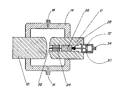
The invention will now be disclosed, by way of example,
with reference to the accompanying drawing which illustrates
a preferred embodiment of an electromechanically triggered
spark gap switch.
The spark gap switch comprises an anode 10 and a
cathode 12 of a size suffici2nt to handle the current
requirement (possibly in the order of 100 kiloamp~ or
higher) of a capacitor discharge circuit without significant

~4Z8~3~ 7~.
power loss. These Qlectrodes are held together along a
common axis with a predetermined gap therebetween by a
uitable insulating housing 14 equipped with conventional
gas intake 16 and outlet 18 for maintaining a sultable gas
pressure within the housing. The cathode has an op~ning
20 in the surface thereof facing the anode and a trigger
electrode 22 is supported in such opening by an insulating
sleeve 24. However, other means o~ mounting the trigger
electrode in the vicinity o~ tha gap between the anode and
lQ cathode are also anvisaged. A piezoelectric generator 26
is connecked to the trigger electroda with one terminal
and to the cathode with its other terminal. The
piezoelectric generator is provided with a conventional
plunger 28 which is operated by the piston 30 of a small
l; pneumatic cylinder 32 when air prsssure is applied to the
intake nozzle 34 of the cylinder.
Inside the piezoelectric generator, a small hammer
strikes a ceramic rod in a known manner. The
piezoelectricity generated i9 substantial, and usually
sxceeds 10 kV. This voltage causes a sparkover between
the trigger electrode and the cathode first, and
subse~uently between tha cathode and anode by local
ionization.
The piezoelectric generator is a common, mass produced
device used in cigaretto lighters and gas stove or gas
barbe~ue lighter~. Air pressurQ can be applied to the
intake nozzle o~ tha pneumatic cylinder through a long
plastic tube or hose providing safe isolation ~or the

~2~ 7~
-5-
operator of the high voltage equipment. Alternatively,
the piezoelectric generator can be operated through an
insulated push bar manually or by a solenoid or other type
of actuator~
Another advantage of the piezoelectric triggering i~
that it converts readily available mechanical energy to
electrical energy. Conventional electronic trigger
circuits operate from isolated power supplies run off line
voltage. In casQ of power failura, the~e trigg~ circuits
become inoperative, but th~ high voltage ~torage
capacitors could remaln charged. Tha Gl~tromechanically
triggered spark gap switch operakes readily during power
failure, making it ideal for crowbar service.
Although the invention has been disclo ed with
reference to a preferred embodiment, it i~ to be
understood that it i~ not limited to such embodiment and
that other alternatives are also envisaged within the
scope of the following claims.

Dessin représentatif
Une figure unique qui représente un dessin illustrant l'invention.
États administratifs

2024-08-01 : Dans le cadre de la transition vers les Brevets de nouvelle génération (BNG), la base de données sur les brevets canadiens (BDBC) contient désormais un Historique d'événement plus détaillé, qui reproduit le Journal des événements de notre nouvelle solution interne.

Veuillez noter que les événements débutant par « Inactive : » se réfèrent à des événements qui ne sont plus utilisés dans notre nouvelle solution interne.

Pour une meilleure compréhension de l'état de la demande ou brevet qui figure sur cette page, la rubrique Mise en garde , et les descriptions de Brevet , Historique d'événement , Taxes périodiques et Historique des paiements devraient être consultées.

Historique d'événement

Description Date
Inactive : CIB désactivée 2020-02-15
Inactive : CIB en 1re position 2020-01-27
Inactive : CIB attribuée 2020-01-27
Inactive : CIB expirée 2012-01-01
Inactive : CIB de MCD 2006-03-11
Inactive : Demande ad hoc documentée 1995-09-17
Le délai pour l'annulation est expiré 1995-03-18
Lettre envoyée 1994-09-19
Accordé par délivrance 1991-09-17

Historique d'abandonnement

Il n'y a pas d'historique d'abandonnement

Titulaires au dossier

Les titulaires actuels et antérieures au dossier sont affichés en ordre alphabétique.

Titulaires actuels au dossier
NORANDA INC.
Titulaires antérieures au dossier
FRANK KITZINGER
Les propriétaires antérieurs qui ne figurent pas dans la liste des « Propriétaires au dossier » apparaîtront dans d'autres documents au dossier.
Documents

Pour visionner les fichiers sélectionnés, entrer le code reCAPTCHA :


Pour visualiser une image, cliquer sur un lien dans la colonne description du document. Pour télécharger l'image (les images), cliquer l'une ou plusieurs cases à cocher dans la première colonne et ensuite cliquer sur le bouton "Télécharger sélection en format PDF (archive Zip)" ou le bouton "Télécharger sélection (en un fichier PDF fusionné)".

Liste des documents de brevet publiés et non publiés sur la BDBC .

Si vous avez des difficultés à accéder au contenu, veuillez communiquer avec le Centre de services à la clientèle au 1-866-997-1936, ou envoyer un courriel au Centre de service à la clientèle de l'OPIC.


Description du
Document 
Date
(aaaa-mm-jj) 
Nombre de pages   Taille de l'image (Ko) 
Page couverture 1993-10-22 1 11
Abrégé 1993-10-22 1 10
Dessins 1993-10-22 1 23
Revendications 1993-10-22 1 28
Description 1993-10-22 5 164
Dessin représentatif 2000-07-07 1 19
Taxes 1993-07-26 1 23