Note : Les descriptions sont présentées dans la langue officielle dans laquelle elles ont été soumises.
1289220
BACKGROUND OF THE INVENTION
The present invention relates to a method of
adjusting the thermal balance of a rotor for a rotary electric
machine and, more particularly, to a rotor thermal-balance
adjusting method in which the rotor is provided with a coolant
passageway, and coolant such as, for example, hydrogen, or the
like, is caused to pass through the coolant passageway to cool
the rotor.
In general, balance adjustment is applied to a
rotary element to reduce shaft-vibration. A method of this
balance adjustment of the rotary element is generally carried
into effect in such a manner that a balance weight is utilized
and is adjusted in magnitude and position to adjust the
balance of the rotary element. This adjusting method is
relatively simple and can balance the rotary element to a high
degree of accuracy.
In the case of a rotor for a rotary electric
machines, however, since the rotor itself is charged with
heat, there occurs deflection of the rotor shaft due to heat,
and local shaft-deformation due to non-uniformity in heat
radiation from the rotor surface, that is, shaft-deformation
due to a thermal in balance, resulting in shaft-vibration. It
is impossible for mere mechanical or formal balancing to
reduce the shaft-vibration.
It is extremely difficult to eliminate the thermal
imbalance. Various researches have been made until now to
avoid the thermal imbalance, and various thermal-balance
~; adjusting methods have been proposed. However, prior to the
~'''':
!t
-.
: .
. ' : -
1289220
present invention, a sufficiently satisfactory method has not
as yet been proposed.
Of the various conventional methods, a relatively
good thermal-balance adjusting method is known from, for
example, Japanese Patent Publication No. 58-40899. In the
method proposed in the Japanese patent, a cooling-medium flow
passageway within the rotor is regulated to eliminate thermal
imbalance. It is possible for this method to effect a
superior thermal balance, if a main component to be corrected
is made clear. It is a problem, however, that the superiority
of this method depends on accurately detecting which component
is to be corrected.
It will suffice for a general rotary electric
machine that the rotor is driven both under a no load
condition and under an actual load condition, a shaft-
vibration component of the thermal imbalance is detected, and
correction is made correspondingly to the shaft-vibration
component of the thermal imbalance. Accordingly, it is
possible with a general rotary electric machine to effect a
thermal balance without any difficulty. It is usual for a
rotary electric machine having a large capacity, however,
that, in spite of the fact that a balance adjustment has
sufficiently been carried out, the thermal imbalance is not so
sufficiently eliminated. The reason for this is that, since
the balance adjustment is carried out within a factory under a
simulated load, and since some of the rotary electric machines
employ, as cooling medium, special gas such as, for example,
hydrogen gas, the cooling condition due to the coolant at
.~ ., .
~ .
.
' . ' ' ' ' '
.
~Z892ZO
adjustment of the thermal balance differs from that when the
machine is operating in the field. That is, even in a rotary
electric machine of the kind referred to above which employs
hydrogen gas as the coolant, hydrogen gas is not used at the
balance adjustment because of explosive danger. It is usual
for such a rotary electric machine to carry out the balance
adjustment by the use of, in general, cooling air as the
coolant. For this reason, even if the rotor itself is the
same in temperature at the actual load condition, flow rate of
the coolant at each section and cooling performance at the
balance adjustment differ from those during actual operation
because hydrogen gas and air perform differently as a coolant
Accordingly, even if the thermal balance is excellent at the
balance adjustment within the factory, the thermal balance is
not necessarily excellent under the practical-use load
condition.
SUMMARY OF THE INVENTION
It is therefore an object of the present invention
to provide a method of adjusting the thermal balance of a
rotor of the kind referred to above, which can effect an
excellent thermal balance even if the practical-use condition
is different from the factory condition.
In accordance with one aspect of the invention there
is provided a method of adjusting a thermal balance of a rotor
provided therein with a heat generating section and a coolant
passageway for cooling the heat generating section, said
method comprising the steps of: detecting a difference in
.
12892ZO
shaft-vibration component of the rotor rotating at a
predetermined speed between a no-load condition of the rotor
and a condition in which the rotor is heated only from the
outside of the rotor and, detecting a difference in shaft-
vibration component of the rotor rotating at a predetermined
speed between a no-load condition of the rotor and a condition
in which the rotor is heated only from the inside of the
rotor; converting the detected differences in shaft-vibratlon
component respectively to differences in shaft-vibration
component under a temperature at an actual load condition in
accordance with a difference in temperature between the no-
load condition and the actual load condition; adding the
converted dif~erences in shaft-vibration component to each
other ln a vector manner to obtain a difference in shaft-
vibration component at the actual.load condition; and
adjusting a flow rate of the coolant within said rotor in
response to the vector-added difference in shaft-vibration
component so that the vector-added difference in shaft-
vibration component is reduced toward zero.
In the method described above, because the
respective imbalances occur linearly with respect to the
temperature rise, the respective difference in shaft-vibration
components are determined in their respective imbalance
directions, and are determined in their respective quantities
by conversion due to the temperature. Accordingly, the
direction and quantity of the difference in shaft-vibration
component which occurs at the actual load can correctly be
known under the simulated setting conditions, making it
~8~3~20
possible to effect an excellent thermal balance even in the
rotary electric machine of the kind referred to above.
BRIEF DESCRIPTION OF THE DRAWINGS
Figs. 1 and 2 are diagrammatic views respectively
showing balance adjusting states for explanation of a thermal-
balanc~ adjusting method according to the invention;
Fig. 3 is a cross-sectional view of a principal
portion of a rotor body section;
Fig. 4 is a diagrammatic view showing an arrangement
of shaft-vibration detecting sensors;
Figs. 5 and 6 are circle diagrams showing
differences in the shaft-vibration component; and
Fig. 7 is a circle diagram representing the
relationship between an electric output and the difference in
shaft-vibration.
DETAILED DESCRIPTION
The invention will be dèscribed below in detail with
reference to an embodiment illustrated in the drawings. Figs.
1 and 2 show a thermal-balance adjusting method according to
the embodiment.
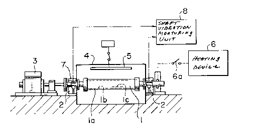
Various component parts and devices will first be
described prior to an explanation of the adjusting method. In
the figures, the reference numeral 1 denotes a rotor to be
adjusted in thermal balance. The rotor 1 comprises a rotor
body section la, and a rotor coil lb which is wound about and
accommodated in the rotor body section la. The rotor 1 is
~289~20
provided therein, for example, with a flow passageway lc for
coolant for cooling the rotor body section la and the rotor
coil lb, as shown in Fig. 3. The flow passageway lc is so
formed as to be capable of adjusting the flow rate of the
coolant to a certain degree.
The rotor 1 is rotatably supported by a pair of
bearings 2, and is adapted to be rotated at a predetermined
rotational speed by an electric drive motor 3 when the rotor 1
is adjusted in balance. Moreover, the body section la of the
rotor 1 is covered by a cover member 4 such that the rotor 1
rotates within the cover member 4-
Arranged in an internal space within the covermember 4 is a heating device 5 for controllably heating the
rotor 1 from the outer peripheral surface of the rotor 1. The
heating device 5 can be replaced with a cooling device if the
rotor surface is excessively hot due to air friction. On the
other hand, a device for heating the rotor 1 from the inside
is designated by the reference numeral 6. That is, the
heating device 6 is an electric power source device which
energizes the rotor coil lb, and heat generated by the copper
loss of the coil lb heats the rotor 1 from the inside. the
electric power source device 6 is.capable of adjusting the
electric current passing through the rotor coil lb. The
reference numeral 6a denotes a switch for the electric power
source device 6.
Designated by the reference numeral 7 at the bearing
2 is a shaft-vibration sensor, and the reference numeral 8
denotes a shaft-vibration measuring device.
~2892ZO
The method of adjusting the thermal balance of the
rotor will now be described. First, as shown in Fig. 1, the
rotor 1 is rotated at the predetermined speed in such a state
that the internal heating device 6 is rendered inoperative
(the switch 6a OFF) and the external heating device 5 heats
the rotor 1. A difference in shaft-vibration of the rotor 1
at this time is detected by the shaft-vibration measuring
device 8 through the shaft-vibration sensor 7. In this case,
a plurality of shaft-vibration sensors 7 are arranged in
circumferentially spaced relation to each other as shown in
Fig. 4, to detect the magnitude of the shaft-vibration and the
direction thereof, that is, a shaft-vibration component.
When the difference in shaft-vibration component
detected at this time is indicated in a circle diagram, there
is obtained a difference in shaft-vibration component P shown
in Fig. 5.
Detection shown in Fig. 2 will next be carried out.
Specifically, the internal heating device 6 heats the rotor 1,
that is, the switch 6a is closed, and a predetermined electric
current is supplied to the rotor coil lb from the electric
power source device 6 so that the rotor 1 is heated from the
inside. In addition, the rotor 1 is rotated and heated also
by the external heating device 5. A difference in the shaft-
vibration component is detected at this time.
lZ89~ZO
When the difference in shaft-vibration component
detected at this time is indicated in a circle diagram, there
is obtained a difference in shaft-vibration component Q shown in
Fig. 5.
The difference in shaft-vibration component Q is a
difference in shaft-vibration component of the rotor heated from
the inside and the outside. From this difference in shaft-
vibration component Q and the aforementioned difference in shaft-
vibration component P, there is obtained a difference in shaft-
vibration component R shown in Fig. 5, that is, a difference in
shaft-vibration component of the rotor heated only from the
inside.
Of course, in this case if the rotor is heated only from
the inside and a difference in shaft-vibration component under the
condition is detected, it is possible to know the component R. In
practice, however, because surface air friction due to rotation of
the rotor causes the rotor surface to be heated, the above-
mentioned process is executed. It is needless to say that if an
especial cooling device is beforehand arranged to prevent the
rotor surface from being heated, the difference in shaft-vibration
component R of the rotor heated only from the inside can easily be
obtained.
The thus detected respective differences in
shaft-vibration component are represented by the following
equations. In the equations, a difference in shaft-vibration
component per one degree of temperature rise of the rotor is A,
and a difference in shaft-vibration component per one degree o~
~.289ZZO
1 temperature rise of the coil is B:
A = - T x P
al aO
1 T x R
b3 bO
where Ta1: rotor shaft temperature after
heating;
Ta0: rotor shaft temperature before
heating;
Tb3: rotor coil temperature after heating;
Tbo: rotor coil temperature before heating;
P : difference in shaft-vibration
component at external heating; and
R : difference in shaft-vibration
component at internal heating.
On the basis of the above results, a vibration
difference vector S at the actual load is indicated as
shown in Fig. 6, because the vibration difference
vector S is the temperature-converted vector sum of
the differences in shaft-vibration component A and B.
If the vibration difference vector S is expressed by
an equation, the equation is represented as follows:
,
( c2 Tc0) x A + (TC3 - Tco) x B
where TC2: rotor shaft temperature after
heating;
1289220
TCo: rotor and shaft temperature before heating; and
Tc3 rotor coil temperature after heating.
The difference in shaft-vibration component ~ is a
thermal imbalance component at the actual load. In practice
use, the coolant flow passageway within the rotor is so
adjusted as to give a component opposite to this difference in
shaft-vibration component S. For instance, as disclosed also
in Japanese Patent Publication No. 58-40899, wedges are moved
axially to adjust the coolant flow rate entering the flow
passageway, thereby adjusting the thermal imbalance occurring
within the rotor of a generator.
The rotor due to the conventional balance adjusting
method and the rotor due to the balance adjusting method
according to the invention will next be compared in effect
with each other, on the basis of the actually measured data
shown in Fig. 7.
Fig. 7 shows the relation between the difference in
shaft-vibration and the output at a predetermined rotational
speed. The rotor offered to the experiment is one generally
called large capacity in which the output is 376 MW and the
rotational speed is 3600 r.p.m.
A straight line Ql indicated by the two-dot chain
line in Fig. 7 represents the difference in the shaft-
vibration component of the rotor not adjusted in thermal
balance, whereas a straight line Q2 represents the difference
in the shaft-vibration component of the rotor adjusted in
thermal balance according to the conventional method. It will
- .
1289220
be seen from Fig. 7 that the difference in shaft-vibration is
considerably reduced by the conventional method. A straight
line Q3, which indicates a further reduction in the difference
in shaft-vibration component than the straight line Q2~
represents the difference in the shaft-vibration component of
the rotor adjusted in thermal balance according to the present
invention. Comparison between these straight lines Qz and Q3
clearly shows that the difference in the shaft-vibration
component in the method of the present invention is
approximately half of the difference of the conventional
method.
As described above, in the present invention, when
obtaining an estimated difference in the shaft-vibration
component of a rotor at an actual load by the use of a
simulated load, at least two independent shaft-vibration
components at the simulated load, that is, a difference in
shaft-vibration component detected while the rotor is heated
from the circumference and a difference in the shaft-vibration
component detected while the rotor coil is energized to heat
the rotor from the inside are detected separately from each
other; these differences in the shaft-vibration component are
theimally converted respectively to the differences in the
shaft-vibration component under a temperature condition at the
actual load. Both the differences in the shaft-vibration
component are added to each other.in a vector manner to obtain
a difference in the shaft-vibration component of the rotor at
the actual load. Accordingly, even if the conditions at the
adjustment of the thermal balance under the simulated load
A
, .
1289220
differs from those at the actual load, and even in the case
where the simulated load largely differs from the actual load,
compensation of the rotor according to the external
temperature and compensation of the rotor according to heating
of the rotor coil are carried out by the temperature
conversion varying linearly, making it possible to find an
excellent thermal balance.
12
'`