Note : Les descriptions sont présentées dans la langue officielle dans laquelle elles ont été soumises.
~2~94~9
-- 2
l~V~ REIAl~?G T~ NOZZLES POR
F~EL INJECIION SYSTE2SS
This invention relates to a method Oc injecting a fuel-air
mi~ture into the cc~mbustion cha~- of an internal cambustion er~ine in
a manner to control the fuel distribution within the chalbber.
The characteristics of the spray of the fuel drcplets issuing
fra:n a nozzle into a c~ustion chamber have major effects on the
efficiency of the bulnir~ of the fuel WhiG~ in turn affects the
stability of the operation of the engine, the fuel efficiency ar~ the
e~aust ~nissions. 1~ optimise these effects m a spark ignited eng~ne
the desirable characteristics of the spray pattern of the fuel issuir~
fram the nozzle include small fuel droplet size, controlled penetration
of the fuel spray into the chamber, and at least at lch~ engine loads a
relatively contained evenly distributed clcud of fuel droplets.
scaTe ~ injèction nozzles, used for 'che delivery of fuel
directly into the c~bbustion chan~er of an engine, are of the pc~pet
valve type fram which the fuel issues in the form of a hollaw diver~ent
conic~l spray, with the fuPl dral?lets form~r~ a continuous wall of the
cone exter~iJ~g frc1m t~ peripheral edge of the pc~pet valve. Ihe
continuous n~ture of the wall of fuel droplets restricts the extent of
atanisation of the fuel, arx3 the dispersion of the fuel droplets in the
a~r to form a fuel mist clcud, which is desirable for ignition and
can~plete combustion of the fuel. Also the continuous wall of fuel
drcplets, issuing as a continuation of the direction of flaw of the
d~oplets fn~m the nozzle, incr~a~es the extent of penetration of the
fuel into the cylinder which is particularly undesirable under light
fuelling conditions.
It is therefore the cibject of the present ir~ention to
pravide a method of injecting fuel t}~h a nozzle into a caribustion
c.hanber, and a nozzle constn~ction, which will contribute to a
reduction in the prcblems experienced with existing nozzles and to
imprcve emissions control and enginR operation s~ability.
~,~
: ~
, ~ . . ..... .
. . . .. .
128942~
-- 3
With this object in view there is provided
according to one aspect of the present invention a method of
injecting fuel into a combustion chamber of a spark ignited
internal combustion engine comprising entraining the fuel in
a gas stream and se.l.ectively opening a port to inject the
fuel-gas mixture so formed into the combustion chamber, and
promoting preferred respective paths for the fue.l-gas mixture
as it passes through the port to produce a c~rcular array of
alternate fi.rst and second flow paths for the fuel-gas
mixture issuing from the open port, with the fuel-gas mixture
following said second paths issuing inwardl.y with respect to
the fue,l,-gas mixture following said first paths.
The fuel,-gas mixture array may be such that the
first and second fl,ow paths diverge outwardly about the axis
of the port to form a generally conical array and the other
regions are in a circu,lar formation about the axis of the
port,~ and are preferably of a converging conical formation.
The dividing of the fuel-gas charge into two flow
:;
paths more widely distributes the charge and so reduces the
ve.l.ocity thereof with resultant reduction in the momentum of
the fue,l droplets and penetration thereof into the combustion
chamber. In this regard it is-
... . .
128942~
-- 4 --desirable for the charge to attain sonic or abcve sonic velocity at the
point of issue from the port in order to promote atomisation. However,
high velocities after entry to the ccmbustion chamker are not desirable
as they result in deep penetration of the fuel into the oombustion
~ mber. me dividing of the fuel-gas charge as currently proposed
assists in permitting sonic velocity of the charge at entry without a
correspondingly high penetration fuel spray.
, m e ~ nge n ~irection of part of the fuel-gas charge to
~J~ ; establish the two~a~r~y6 also reduces the velocity of that part of the
fuel-gas charge with respect to the part that does not change
direction, thus further reducing fuel penetration. Also it is believed
that the change in direction is m~re readily acccm=ol~bed by the gas
than the fuel droplets, due to the relative densities and resulting
~c3entum effects, and so the inner array is of somewhat lower density.
It is believed that the effect of the hollow spray is that, due to
entrainment-induced effects in the gas with m the conioal array,
vortices are produced adjacent the array within the hollow spray of
fuel-gas charge
lssuing from the port. m is vortex production effect ls partlcularly
effective
when the liquid fuel is entrained in a gas as c~mpared with a liquid
fuel alone injection syst~m. In the liquid alone injection system
there is minimum expansion as the fuel issues thrcugh a port and so any
vortex production effects only extend to the gas in the ccmbustion
chamber within the area immediate to the spray.
In contrast in the present proposal, where the liquid fuel is
entrained in gas, the substantial pressure drop through the port w~ll
result in a substantial expansion of the gas issuing into the
~ombustion chlmber with the fuel. m e vortex production effect is thus
m~re widely ~pread and the li~uid fuel droplets r~rried in the gas are
similarly spread. m e above reference to the wide spread of the vortex
production effect refers to a spread within the ambit of the fuRl spray
issu m g from the port and not to substantial spread thrcughout the
whole combustion chamber.
The averall effect of entraining the fuel in a gas and
injecting the fuel-gas charge so created into the comkustion chamber
in the form of two concentric arrays of fuel drcplet streams, i5 to
128942~
limit the extent of penetration of the fuel into the chamber,
and to provide a confined fuel cloud, with fuel distributed
therethroughout, at the injection point.
When the array is circular or conical, a toroidal air
flow is created within the formation generally concentric
therewith. The air flow in the outer region of the toroid
complements that of the fuel droplets issuing from the port,
and fuel becomes entrained in the toroidal air flow to be
carried inward of the formation. This dispersion of the fuel
droplets contributes to the distribution of the fuel while
retaining it within a defined area.
The invention also provides a fuel injection system for
internal combustion engines where fuel entrained in gas is
in~ected into a combustion chamber as a fuel-gas mixture, flow
means for providing a circular array of alternate first and
second flow paths for the fuel-gas mixture when the mixture
is being injected into the combustion chamber with the fuel-
gas mixture following said second flow paths issuing into the
combu~tion chamber inwardly with respect to the fuel-gas
mixture following said first flow paths.
The fuel in~ection system may include a selectively
openable nozzle means through which the fuel-gas mixture is
in~ected into the combustion chamber, and flow divider means
in the path of the mixture issuing through the nozzle when
open, for forming said circular array of alternate fir~t and
second flow paths. The nozzle means may include a port and
a valve element operable to selectively open and close said
port. The valve element and port having respective portions,
defining therebetween when the port is open, a passage from
which the fuel-gas mixture will issue into the combustion
chamber, one of said portions incorporating said flow divider
means. The flow divider means may comprise discontinuitie~
in said one portion at that edge from which the mixture
issues, for deflecting the fuel-gas mixture passing through
the discontinuities from the trajectory of the remainder of
the fuel-gas mixture such that the mixture is deflected
inwardl~ with respect to the mixture passing the remainder of
said edge to follow said second paths. Conveniently the
. .
~289429
-5a-
discontinuities comprise a plurality of spaced notches in the
valve element.
/
128942~
--6--
Preferably the movable valve is provided with a plurality
of notches spaced around the periphery of the terminal edge
portion. The provision of these notches provides two
alternative sets of paths for the fuel-gas mixture, an outer
set formed by the un-notched portions of the terminal edge of
the valve, and the other set passing through the notches to
be thereby displaced radially inward from the terminal edge
of the valve element.
The surface of the valve element which the fuel-gas
mixture passes when the nozzle is open is preferably of a
divergent conical form so that the fuel-gas mixture issuing
from the terminal edge will initially maintain this direction
of flow to form an outer array of gas entrained fuel droplets.
However, where the terminal edge is interrupted by the notches
the fuel and gas presented to the notch will flow therethrough
to issue from the nozzle inwardly of the terminal edge.
The wall attachment effect present when a fluid is
flowing along a surface i8 believed to also contribute to the
nature of the flow of the gas and fuel mixture through the
notches.
~ t is believed that the gas is more susceptible to the
wall attachment effect than the fuel and, together with the
effects of the surface tension of the fuel, result in some
shedding of ~uel from the fuel-gas mixture at the edge of the
notch which is first encountered by the mixture passing over
the valve element. The shed fuel is directed to flow aroundj
rather than through the notch and 80 becomes entrained and
enriches the fuel-gas mixture flowing down the un-notched
areas of the valve element. The momentum effects on the fuel
may also contribute to some shedding of fuel from the gas
diverted through the notches. This breaking up of the fuel-
gas mixture into a plurality of arrays of fuel droplets
streams provides a greater access for the fuel droplets to mix
with the gas, and the additional edge length derived by
1289429
the provision of notches increases the effect of shear mg on the fuel
droplets to achieve greater atomisation of the fuel.
The streams of fuel-gas mixture issuing from the terminal
edge of ~he valve element in a conical formation establishes a tor~idal
like vortex flow within the confines of the conical formation. The
direction of this toroidal vortex flow is such that the radial outer
part thereof, adjacent the fuel-gas streams in the conical formation,
is moving in the same direction as those streams~ m is flow picks up
fuel droplets fram the streams and carries them inwar*ly of the co~ical
formation. m e result is that the fuel-gas streams are further broken
up to increase distribution of the fuel, and to form a contained fuel
mist cloud exbending across the full extent of the conical formation
initiated by the fuel-gas stream issuing from the valve element. m e
breaking up and drawing inwardly of the fuel-gas mixture alsD lImits
the depkh of penetration of the fuel into the combustion chamber and so
may retain a rich mixture in the area of a spark plug in the region of
the fuel injector for ready ignition, and limits dispersion of fuel
into remote areas of the ccmbustion chamber.
Ihe fuel-gas cloud contains a c~nstrained mass of fuel
droplet6 finely dispersed and mixed with sufficient air to provide a
readily ignitable fuel charge.
Ihe i~vention will be more readily urdbr~tood from the
following description of a practic~l arrangement of apparatus for
delivering fuel to an engine and several constructians of the valve
control nozzles thrc~h which a fuel-air mixture is delivered to the
ccmbustion cha~ber of an engine.
In the drawings:-
Figure 1 is a longitudinal sectional view of a tWD strbkecycle engine to which the presently prcposed fuel in~ection method and
apparabus is applied.
Figure 2 is an elevational view partly in section o~ a fuel
metering and injection devioe for which the present invention is
applicable. It is shcwn diagrammatically coupled to its associated
fuel and air supply.
Figures 3 and 4 are ~end and side elevational views of one
form of valve head embodying the present invention.
Figures 5 and 6 are end and side elevation21 views of another
~.X~39~29
form of valve head embodying the present invention.
Figure 7 is a sectional view to a large scale of part of the
valve similar to that shown in Figures 5 and 6 and a complementary port
and valve sea~.
Figure 8 is a perspective view of a valve port incorporating
a further form of the present m vention.
Figure 9 illustrates the fuel cloud formation achie~ed with
the valve head shape shown in Figures 5 to 6.
Figure 10 is a sectional view ~hrough the fuel clcud shown in
Figure 9 illustrating flcw patterns in the fuel cloud.
Fig~re 11 is a graph showing a comparison of the HC content
of the exhaust gas from engines operating with a plain pcppet valve and
the same engine with a notched poppet valve~
Referring now to Figure 1 the engine 9 is a single cylinder
two-stroke cycle engine, of generally conventional construction, having
a cylinder 10, crankcase 11 and piston 12 that reciprocates in the
cylinder 10. The piston 12 is ccupled by the connecting rcd 13 to the
cr~nkshaft 14. The czankc3su is provided with air induction ports 15,
incorporating conventional reed valves lg and three transfer passages
16 (only one shown) ccmmunicate the crankcase with respective transfer
ports, two of which are shown at 17 and 18, the third being the
e~uivalent to 17 on the opposite side of port 18.
The transfer ports are each formed in the wall of the
cylindex 10 normally with their respective upper edge located in the
same diametral plane of the cylinder. An exhaust port 20 is formed in
the wall of the cylinder generally opposite the central transfer port
18. qhe upper edge of the exhaust port is slightly above the diametral
plane of the transfer ports u~per edges, and wilI accordingly close
later in the eng me cycle.
m e detachable cylinder head 21 has a comkustion cavity 22
into which the spark plug 23 and fuel injector nozzle 24 project. The
cavity 22 is located substantially symmetrical with respect to the
axial plane of the cylinder extcnding through the centre of the
transfer port 18 and exhaust port 20. m e cavity 22 extends across the
cylinder from the cyl mder wall immediately above the transfer port 18
to a distance past the cylinder c~ntre line.
The cross sectional shape of the cavity 22 along the abcve
, i
lZ8942~
referred to axial plane of the cylinder is substantially
arcuate at the deepest point to base 28, with the centre line
of the arc somewhat closed to the centre line of the cylinder
than to the cylinder wall above the transfer port 18. The end
of the arcuate base 28 closer to the cylinder wall above the
transfer port 18, merges with a generally straight face 25
extending to the under face 29 of the cylinder head 21 at the
cylinder wall. The face 25 is inclined upwardly from the
cylinder wall to the arcuate base 28 of the cavity.
The opposite or inner end of the arcuate base 28 merges
with a relatively short steep face 26 that extends to the
under face 29 of the cylinder head. The face 26 also meets
the underface 29 at a relatively steep angle. The opposite
side walls of the cavity ~one only being shown at 27) are
generally flat and parallel to the above referred to axial
plane of the cylinder, and so also meet the underface 29 of
the cylinder head at a steep angle.
The injector nozzle 24 is located at the deepest part of
the cavity 22, while the spark plug 23, is located in the face
of the cavity remote from the transfer port 18. Accordingly,
the air charge entering the cylindsr will pass along the
cavity past the injector nozzle 24 toward the spark plug and
BO carries the fuel from the nozzle to the spark plug.
Further details of the form of the cavity 22 and of the
combustion process derived therefrom are disclosed in British
Patent No. 2 175 953 and United States Patent No. 4 719 880.
The in~ector nozzle 24 is an integral part of the fuel
metering and in~ection system whereby fuel entrained in air
is delivered to the combustion chamber of the engine by the
pressure of the air supply. One particular form of fuel
metering and in~ection unit is illustrated in Figure 2 of the
drawings.
The fuel metering and injection unit incorporates a
suitably available metering device 30, such as an automotive
type throttle body injector, coupled to an injector body 31
having a holding chamber 32 therein. Fuel is drawn from the
fuel reservoir 35 delivered by the fuel pump 36 via the
pressure regulator 37 through fuel inlet port 33 to the
metering device 30. The metering device operating in a known
1289429
--10--
manner meters an amount of fuel into the holding chamber 32
in accordance with the engine fuel demand. Excess fuel
supplied to the metering device is returned to the fuel
reservoir 35 via the fuel return port 34. The particular
construction of the fuel metering device 30 is not critical
to the present invention and any suitable device may be used.
In operation, the holding chamber 32 is pressurised by
air supplied from the air source 38 via pressure regular 39
through air inlet port 45 in the body 31. Injection valve 43
is actuated to permit the pressurised air to discharge the
metered amount of fuel through injector tip 42 into a
combustion chamber of the engine. Injection valve 43 is of
the poppet valve construction opening inwardly to the
combustion chamber, that is, outwardly from the holding
chamber.
The injection valve 43 is coupled, via a valve stem 44,
which passes through the holding chamber 32, to the armature
41 of solenoid 47 located within the injector body 31. The
valve 43 is biased to the closed position by the disc spring
40/ and i8 opened by energising the solenoid 47. Energising
of the solenoid 47 is controlled in timed relation to the
engine cycle to effect delivery of the fuel from the holding
chamber 32 to the engine combustion chamber.
Further details of the operation of the fuel injection
system incorporating a holding chamber is disclosed in
Australian Patent No. 567037, U.S. Patent No. 4 693 224 and
Belgian Patent No. 903515.
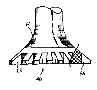
Preferred forms of the head portion of the
in;ection valve 43 are shown in Figures 3 to 6 which
depict two views of two alternative forms of valve head
intended to be used with a basically conventional valve seat.
As seen in each of Figures 3 and 5, there are twelve equally
spaced notches or slots 65 about the periphery of the head 48
of the valve, and an annular sealing face 61, which in
use co-operates with a corresponding sealing face on
a co-operating valve seat as indicated at 68 in Pigure 7.
The included angle of the sealing face in these preferred
forms is 120 but may be at any other appropriate angle
1289429
-- 11 --
such as, for example, the scmetimes used 90 angle. In the cmbodiments
~,hown the annular ~ortion 62 of the valve head, m which the notches
are provided, has the same included angle of taper as the seal mg face
61, however this is not essential. For example, if the included angle
of the sealing face is 90 the angle of the annular portion 62 may be
.20 .
In each of the embod~ments shown the twelve notches 65 are
equally spaced around the perimeter of the head, and the opposite walls
66 are radial and have an included angle therebetween of 15 . In the
specific valves shcwn in the draw mgs the overall diameter of the valve
head is 4.7 mullimetres while the width of the notch at the periphery
is 0.7 millimetres and a total notch depth on the centre line of ~he
notch and in the direction radial to the head is 0.7 miilimetres.
- m e width of notches may vary to suit particular performance
~equ1rcments and preferably the nothces occupy 35 to 65% of the length
of the edge in which they are located. Usually the notches occupy 40
to 60% of said edge length.
In the embodlment shown in Figures 3 and 4 the base 67 of
each nokch is Farallel to the axis of the valve.
~ n alternative ¢cnstructions the base of the notch may be of
a configuration other than parallel to the axis of the valve, and
typically may be mcl med downwardly and inwardly towards the axis of
the valve as at 167 m Figure 6. In this e~bcdiment the angle of the
inclined base to the a~is of the valve is 30 . In other variations
(not shown) the base of the notch is curved in the directian frcm the
top to the baktom of ~he valve head rather than flat.
Further, in the e~bodime~ts shown the oppcsite side walls 66
of the notches are in radial planes parallel to the axis of the valve,
however, the notches may be arranged so that the side walls thereof are
in planes inclined to the valve axis, and typically the inclination ~ay
be of order of 30 .
It is understaad that the base 67, 167 of the not~h in the
above referred to embcdiments need not be sLraight in the plane of the
notch as shown in Figures 4 and 6 but may be of an arcNate form
blending smoothly with the opposite side walls 66 of the nokch. Also
the shape of the land 69 between respective notches may be of generally
semi-circular cross section rather than of an arcuate fa~m as shown in
12~39429
- 12 -
Figures 4 and 5 corresponding to the peripheral contour of the valve.
Figure 7 of the drawings shows in part a poppet type value,
as above described, and the co-operating part of a port. m e CP~ling
face 68 of the port co-operates with the sealing face 61 of the valve
~ead 48 when the valve is in the closed position. An annular p æsage
75 is formd between these sealing faces when the valve is cpen (as
shown) through which the fuel-air mixture flows to be delivered into
the combustion chamber.
me recessed face 76 of the port, downstream fr~m the sealing
face 68, has a clearance with respect to the notched portion 62 of the
v21ve head 48. m is clearance reduces the risk of defective sealing of
the valve as a result of carbon particles or other foreign m~tter on
the face 76. Also as the valvc doe~5not contact the face 76 when closed,
carbon particles initially deposited thereon are likely to be sweeped
off by the fuel-air charge passing when the valve is open.
me notches in the periphery of the valve head divide the air
entrained fuel flow into respective paths, that which p æ ses over the
normal peripheral ed~e of the valve, and that whidh passes thrcugh the
nokche~. Th~P respective flow paths in effect ~orm the ccroentric
arrays of air entrained fuQl dr~plets and are depicted in Figure 9 at
71 and 70. The streams 70 issu m g fram the un-notched portion of the
valve edged may be samewhat richer in fuel than the streams 71, as
previously discussed. It will also be appreciated that the prcvision
of the notches increases the flow pat'h area for the gas and fuel and so
reduces their velocity and thus the extent of penetration into the
c~mbustion chamber. Also the effective functioning of this valve is
less dependent on smooth surfaces and uninterrypbel flow, and so carban
built up on the valve and port surfaces are not a major prcblem.
Figure 9 depicts ~he extern21 apQcar~nce of the two arrays of
fuel streams 70 and 71 and the resulting fuel cloud 72, and show that
as the streams move some distance fram the nozzle and ' hQnce
decellerate, the streams bre~k up into a fuel mist. This mist is
carrled inwzrdly frcm the koundary array to form wlthin the general
confine of the streams a generally continuaus clau~ of fine droplets of
fuel dispersed within a body of air.
Figure 10 is a sectional view which illustrates the baslc
flows associated with the formation of the fuel cloud 72. It will be
1289429
- 13 -
noted that the st~eams 70 of air and fuel issue from the edge of the
pcppet valve on a diveryent path, and so provide a pressure gradient
below the valve head ~3, which develops a generally toroidal air flow
73 within the volume bounded by the fuel-air streams 70. Ihe path of
the toroidal flow adjacent the streams 70 is in the same directicn
thereas, and the outer portion of the toroidal air flcw will take up
fuel drcplets from the streams 70 and 71 and carry them inwardly to be
dispersed within the air moving in the toroidal flow, which assis~s in
breaking up and slowing down the air-fuel streams 70 and 71. mus the
effect of this toroidal air flow 73 is to generally prevent outward
dispersion of the fuel droplets which wol~1d cause a relatively
dispersed fuel cloud, and to carry the fuel drops tcwards the centre so
that a concentrated fuel cloud 72 is established.
Although the preferred form of the invention has a series of
notches in the p~rimetal area of the poppet valve head, keneficial
results are also achieved with a series of notches in the port together
with a ¢onventional poppet valve without notches. A typical
con~iguration of a notched port is ~hcwn in Figure 8.
Ihe port has an annular sealing face 80 which in use
cc-cper~tes with a correspcnding sealing face on a poppet valve
Dcwnstream of the sealing face 80 is an annular end face 81 generally
normal to ~he port axis, and an irtcrccrncct1ng generally cylindrical
internal face 84. Twelve equally spaced notches 82 arei formed in the
end face 81 extend~ng from the ~nternal fa¢e 84 to the external
perl~heral face 83. Preferably ffhe cpposite walls 85 of t;he nokches
are parallel. Ihe base of the nokches is preferably flat, and parall.el
t~ the end face 81. The depth of ffhe n ~ is su~h that ffhat part of
the fuel-air charge travelling thrcugh the port t~wards the not~h when
the valve is open, will not impinge on the cylindrical surfaoe 84 and
will pass through the notch urimpeded. Ihe part of the fuel-air charge
that does impLnge on the cylindri~l surfaoe 84 be*ween the nckdhes 82
is deflected to travel along that face.
Ihe above described arrangement of nc~ches in the port will
divide the fuel-air mlxture issuing fram the port into two arrays of
fuel droplets, an outer array issu mg through the nckches 82 and an
inner array issuing from the un-notched portions of the internal faoe
81. In this arrangement the outer array is divergent with re#pect to
128942~
- 14 -
the axis of the pcrt generally continuing in the ~ ion of the
sealing.faoe 80 while the inner array is generally of a cylindrical
f.orm follow m~ the mtern21 faoe 81.
I~e fuel cloud created by the notched port is mcre widely
~isFersed than the that result mg from a notched valve head of the
~ame angle. It is also less penetrating, ~o the resultant fuel cloud
ray be principally retaLned within a oosbustiQn cavity prcvided in the
cylinder head such as the cavity 22 in Figure 1. Also when using the
abave not~ed port oonfigur~tic~ ays of fuel dr~lets
pravide an ~d e7~ of t~ ~uel to air to pm~
Figure 11 contains plots of hydrocarbon content
in the exhaust gas obtained from operating the same engIne
with a conventional poppet valve in the in~ector and ~ith
a notched poppet valve similar to that sho~n in Figures 3
and 4.
The solid line indicates the hydrocarbon content
oi the exhau~t gas with the conventional poppet valve and
the broken line hydrocarbons with the notched poppet valve.
The engine used in this test was intended for automobile
use where the majority of operation is in the low to medium
power range, and this is the operating range where the
notched poppet valve provided the higher rate of reduction
of hydrocarbon in the exhau~t gas. The notched poppet
also contributes to a reduction in NOx in the exhaust, but
to a lesser extent than the effect on hydrocarbons. The
notched poppet is thus a developmen~ that contributes
significantly to the control of emissions in the exhaust
of internal combustion engines, particularly automobile type
engines.
~28942~
--15--
It is to be understood that the present invention may be
applied to any form of fuel injection system wherein the fuel
is entrained in air or another gas, particularly a combustion
supporting gas, and is delivered into a combustion chamber
through a nozzle.
In one particular fuel injection system a metered
quantity of fuel is delivered into a body of air and the so
formed fuel and air mixture is discharged through a nozzle to
the engine combustion chamber, upon opening of the nozzle by
the pressure differential existing between the body of air and
the combustion chamber. The body of air may be static or
moving as the fuel is metered thereinto. The mode of metering
the fuel may be of any suitable type including pressurised
fuel supplies that issue for an adjustable time period into
the air body, or individual measured quantities of fuel
delivered, such as by a pulse of air, into the body of air.
Fuel injection systems and metering devices suitable for
use in carrying the pre~ent invention into practice are
di~closed in our U.S A. Patents Nos. 4,462,760 4,554,945,
Australian Patent No. 567 037 and Belgian Patent No. 903515.
In the present specification specific reference has been
made to the use of the present invention in con~unction with
an engine operating on the two-stroke cycle and with spark
ignition, however it i5 to be understood that the invention
is equally applicable to spark ignited engines operating on
the four stroke cycle. The invention is applicable to
internal combustion engines all uses but is particularly
useful in contributing to fuel economy and control of exhaust
emissions in engines for or in vehicles, including
automobiles, motor cycles and boats including outboard marine
engines.