Sélection de la langue

Search

Sommaire du brevet 1289481 

Énoncé de désistement de responsabilité concernant l'information provenant de tiers

Une partie des informations de ce site Web a été fournie par des sources externes. Le gouvernement du Canada n'assume aucune responsabilité concernant la précision, l'actualité ou la fiabilité des informations fournies par les sources externes. Les utilisateurs qui désirent employer cette information devraient consulter directement la source des informations. Le contenu fourni par les sources externes n'est pas assujetti aux exigences sur les langues officielles, la protection des renseignements personnels et l'accessibilité.

Disponibilité de l'Abrégé et des Revendications

L'apparition de différences dans le texte et l'image des Revendications et de l'Abrégé dépend du moment auquel le document est publié. Les textes des Revendications et de l'Abrégé sont affichés :

  • lorsque la demande peut être examinée par le public;
  • lorsque le brevet est émis (délivrance).
(12) Brevet: (11) CA 1289481
(21) Numéro de la demande: 1289481
(54) Titre français: DRAIN A INSTALLER DANS DES PLANCHERS DE BOIS
(54) Titre anglais: DRAIN SUITED FOR INSTALLATION IN WOODEN FLOORS
Statut: Périmé et au-delà du délai pour l’annulation
Données bibliographiques
(51) Classification internationale des brevets (CIB):
  • E04F 17/00 (2006.01)
  • E03F 05/04 (2006.01)
  • E04D 13/04 (2006.01)
(72) Inventeurs :
  • EMBERSON, JOHN E. (Canada)
(73) Titulaires :
  • WATTS INDUSTRIES (CANADA) INCORPORATED
(71) Demandeurs :
  • WATTS INDUSTRIES (CANADA) INCORPORATED (Canada)
(74) Agent: MCCARTHY TETRAULT LLP
(74) Co-agent:
(45) Délivré: 1991-09-24
(22) Date de dépôt: 1988-01-14
Licence disponible: S.O.
Cédé au domaine public: S.O.
(25) Langue des documents déposés: Anglais

Traité de coopération en matière de brevets (PCT): Non

(30) Données de priorité de la demande: S.O.

Abrégés

Abrégé anglais


ABSTRACT
A drain suitable for installation in a wooden floor
comprises a body, a grate frame secured to the top of the body, a
grate mounted in the frame and a projecting annular flange
secured between the body and the grate frame for screw attachment
to a deck of the floor.

Revendications

Note : Les revendications sont présentées dans la langue officielle dans laquelle elles ont été soumises.


We Claim:
1. A floor drain comprising:
a tubular body;
a grate frame secured to one end of said body;
a grate positioned by said grate frame to overlie said one end;
means to secure said body to said grate frame, and
securing means having upper and lower surfaces and
allowing said body to be secured to said grate frame, said
securing means extending outwardly of said grate frame at a
location so that said lower surface overlies a floor deck and
being dimensioned so that the upper surface thereof is
substantially level with flooring placed on said floor deck.
2. A drain according to claim 1 wherein said securing
means comprises an annular flange.
3. A drain according to claim 2 wherein an inner
peripheral portion of said securing means is held between
adjacent portions of said body and said grate frame.
4. A drain according to claim 3 wherein a sealing compound
is applied to opposing surfaces of said securing means and said
body and said grate frame.
5. A method of installing a drain having a tubular body, a
grate frame secured to one end of said body, a grate positioned
by said grate frame and overlying said one end and securing means
extending outwardly of the grate frame in a floor comprising the
steps of:
forming an opening in the deck of said floor of greater
size than said grate frame;
disposing the drain in said opening with the securing
means extending over the marginal edges of the deck about said
opening; and
fastening said securing means to the deck,
-6-

6. The method of claim 5 wherein said securing means
includes an annular flange overlying the marginal edges of the
deck about said opening and wherein screws are passed through
said flange and into said deck to fasten said flange thereto.
-7-

Description

Note : Les descriptions sont présentées dans la langue officielle dans laquelle elles ont été soumises.

~2~3~48~
-- 2
BACKGROUND OF THE INVENTION
This invention is concerned with floor drains and one
which is particularly but not exclusively, suited for
installation in a wooden floor.
A conventional drain has a body which is set in
concrete, a grate frame secured to the top of the body and a
grate mounted in the frame. Placing such a drain in a new
concrete floor is a simple matter; one merely positions the drain
body and pours the concrete. However, placing such a drain in a
wooden floor is rather more difficult. The standard technique is
to locate a pair of transverse forms between adjacent joists,
secure a base form to the joists and transverse forms, locate the
drain and pour concrete into the form constituted by the
transverse forms, the base form and the ~oists to which they are
attached.
The pre~ent inventlon seeks to simplify the task of
setting a drain into a wooden floor.
SUMMARY OF THE INVENTION
According to one aspect of this invention, there is
provided a floor drain comprising:
a tubular body;
a grate frame secured to one end of said body;
a grate positioned by said grate frame to overlie said
one end;
means to secure said body to said grate frame; and
secur~ng means having upper and lower surfaces and
allowing said body to be secured to sald grate frame, said
securing means extending outwardly of said grate frame at a
location so that said lower surface overlies a floor deck and
. ' ' ' ' -

12894~1
being dimensioned so that the up~er surface thereof is
substantially level with flooring placed on said floor deck.
Preferably, the securing means comprises an annular
flange with screw openings through which screws may be passed to
hold the securing means to the deck. The inner portion of the
securing means is desirably clamped between the body and the
grate frame.
According to another embodiment of this invention,
there is provided a method of installing a drain having a tubular
body, a grate frame secured to one end of said body, a grate
positioned by said grate frame and overlying said one end and
securing means extending outwardly of the grate frame in a floor
comprising the steps of:
orming an opening in the deck of said floor of greater
size than said grate frame;
dlsposing the drain in said opening with the securing
means extending over the marginal edges of the deck about said
opening; and
fastening said securing means to the deck.
An embodiment of the present invention will now be
described with reference to the accompanying drawings in which:
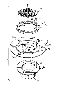
Figure 1 is an exploded perspective view of a floor
drain,
Figure 2 is a perspective view of the drain of Figure 1
in assembled form with parts cut away for the purposes of
illustration; and
Figure 3 is a cross-sectional view showing the drain
installed in a finished floor.
,

1;~8:9~
- 3a -
The drain comprises a body 10 of generally cylindrical
form ~hich, in this instance, is internally threaded as at 12 for
attachment to an appropriately threaded drain pipe. At the upper
edge of the body there is an integral, outwardly directed
peripheral flange 14 with three equi-angularly spaced bosses 16
extending from the lower surface of the flange to the outer
surface of the cylindrical portion of the body 10. Axially
disposed blind threaded holes are formed in the bosses for the
attachment of an annul ar frame grate 18.
The frame grate is of angle section having a radially
-A ` ~
,
.
: .

48~
-- 4
disposed leg 20 which partially overlies the upper surface of
flange 14 of the body and an axial leg 22.
Securing means S comprises a generally axially disposed
annular web 26, a radially disposed flange 28 extends inw~rdly
from the lower edge of web 26 between the upper surface of flange
14 of the body and the lower surface of the radially disposed leg
of the grate frame and has equiangularly disposed holes 28a
formed in it. A radially disposed flange 30 extends radially
outwards from the upper edge of the we~ portion 26. A suitable
sealing compound is disposed between the adjacent surfaces of
flange 28 and the body and grate frame to prevent leakage.
Screws 24 are passed through holes in the leg 20 of the grate
frame and through holes 28a of flange 28 registering with the
blind threaded holes in bosses 16 to secure the grate frame and
the securing means to the body.
The securing means is designed so that the upper
peripheral edge of the grate frame is at a height above the upper
surface of the flange 30 equal to the height of the flooring, be
it linoleum or tile or any other finishing material, to be
applied to the deck in which the drain is to be located.
Set into the grate frame in conventional fashion is a
grate 32.
To install the drain, one simply cuts a circular hole
in the deck 34 of a diameter slightly larger than the diameter of
the web portion of the securing means 24. The drain is then
inserted into that opening with flange 30 of the securing means
24 supported on the deck. The drain is secured in place by
screws passed through the equi-angularly spaced holes 36 of the
flange 30. Thereafter, flooring is applied in conventional
fashion over flange 30 and up to the marginal edges of the grate
.. . .

~2~ 8~
-- 5 --
frame and the piping is connected to the body 10 in conventional
fashion.
It will be recognized by those skilled in the art that
the use of the embodiment of the invention here illustrated means
that drains can be installed in wooden floors in a much more
convenient and simple manner than has been the case in the past.
It is also to be appreciated that the securing means could
conceivably be formed integrally with either the body of the
drain or with the frame grate. However, by the use of the
particular embodiment here illustrated, certain economies of
materials and manufacturing dies and molds are achieved. It is
further to be understood that while the flange of the securing
means is illustrated as being continuous, it is conceivable that
simple lugs could be used for this purpose. If resort would be
had to lugs, they would necessarily have to be more sturdy than
the continuou8 flange of the pre8ent embodlment.
,
'
.

Dessin représentatif
Une figure unique qui représente un dessin illustrant l'invention.
États administratifs

2024-08-01 : Dans le cadre de la transition vers les Brevets de nouvelle génération (BNG), la base de données sur les brevets canadiens (BDBC) contient désormais un Historique d'événement plus détaillé, qui reproduit le Journal des événements de notre nouvelle solution interne.

Veuillez noter que les événements débutant par « Inactive : » se réfèrent à des événements qui ne sont plus utilisés dans notre nouvelle solution interne.

Pour une meilleure compréhension de l'état de la demande ou brevet qui figure sur cette page, la rubrique Mise en garde , et les descriptions de Brevet , Historique d'événement , Taxes périodiques et Historique des paiements devraient être consultées.

Historique d'événement

Description Date
Inactive : CIB de MCD 2006-03-11
Le délai pour l'annulation est expiré 2001-09-24
Inactive : Demande ad hoc documentée 2001-01-16
Lettre envoyée 2000-09-25
Accordé par délivrance 1991-09-24

Historique d'abandonnement

Il n'y a pas d'historique d'abandonnement

Historique des taxes

Type de taxes Anniversaire Échéance Date payée
TM (catégorie 1, 6e anniv.) - petite 1997-09-24 1997-07-25
TM (catégorie 1, 7e anniv.) - petite 1998-09-24 1998-09-23
TM (catégorie 1, 8e anniv.) - petite 1999-09-24 1999-09-03
Titulaires au dossier

Les titulaires actuels et antérieures au dossier sont affichés en ordre alphabétique.

Titulaires actuels au dossier
WATTS INDUSTRIES (CANADA) INCORPORATED
Titulaires antérieures au dossier
JOHN E. EMBERSON
Les propriétaires antérieurs qui ne figurent pas dans la liste des « Propriétaires au dossier » apparaîtront dans d'autres documents au dossier.
Documents

Pour visionner les fichiers sélectionnés, entrer le code reCAPTCHA :


Pour visualiser une image, cliquer sur un lien dans la colonne description du document (Temporairement non-disponible). Pour télécharger l'image (les images), cliquer l'une ou plusieurs cases à cocher dans la première colonne et ensuite cliquer sur le bouton "Télécharger sélection en format PDF (archive Zip)" ou le bouton "Télécharger sélection (en un fichier PDF fusionné)".

Liste des documents de brevet publiés et non publiés sur la BDBC .

Si vous avez des difficultés à accéder au contenu, veuillez communiquer avec le Centre de services à la clientèle au 1-866-997-1936, ou envoyer un courriel au Centre de service à la clientèle de l'OPIC.

({010=Tous les documents, 020=Au moment du dépôt, 030=Au moment de la mise à la disponibilité du public, 040=À la délivrance, 050=Examen, 060=Correspondance reçue, 070=Divers, 080=Correspondance envoyée, 090=Paiement})


Description du
Document 
Date
(aaaa-mm-jj) 
Nombre de pages   Taille de l'image (Ko) 
Abrégé 1993-10-21 1 16
Revendications 1993-10-21 2 46
Dessins 1993-10-21 2 55
Description 1993-10-21 5 149
Dessin représentatif 2002-01-20 1 10
Avis concernant la taxe de maintien 2000-10-22 1 178
Correspondance 2000-10-22 2 130
Taxes 1998-09-22 1 39
Taxes 1997-07-24 1 40
Taxes 1999-09-02 1 33
Taxes 1996-09-30 1 47
Taxes 1995-07-04 1 34
Taxes 1994-06-20 1 42
Taxes 1993-09-23 1 30