Sélection de la langue

Search

Sommaire du brevet 1289587 

Énoncé de désistement de responsabilité concernant l'information provenant de tiers

Une partie des informations de ce site Web a été fournie par des sources externes. Le gouvernement du Canada n'assume aucune responsabilité concernant la précision, l'actualité ou la fiabilité des informations fournies par les sources externes. Les utilisateurs qui désirent employer cette information devraient consulter directement la source des informations. Le contenu fourni par les sources externes n'est pas assujetti aux exigences sur les langues officielles, la protection des renseignements personnels et l'accessibilité.

Disponibilité de l'Abrégé et des Revendications

L'apparition de différences dans le texte et l'image des Revendications et de l'Abrégé dépend du moment auquel le document est publié. Les textes des Revendications et de l'Abrégé sont affichés :

  • lorsque la demande peut être examinée par le public;
  • lorsque le brevet est émis (délivrance).
(12) Brevet: (11) CA 1289587
(21) Numéro de la demande: 1289587
(54) Titre français: DISPOSITIF POUR FERMER LE JOINT AUX LANCES RETRACTILES DE SOUFFLAGE SES SUIES
(54) Titre anglais: APPARATUS FOR SEALING RETRACTABLE SOOT-BLOWER LANCES
Statut: Périmé et au-delà du délai pour l’annulation
Données bibliographiques
(51) Classification internationale des brevets (CIB):
  • F28G 03/16 (2006.01)
  • F28G 01/16 (2006.01)
  • F28G 15/00 (2006.01)
(72) Inventeurs :
  • ALBERS, KARL (Allemagne)
  • TEMMINGHOFF, ALFONS (Allemagne)
(73) Titulaires :
  • GERGEMANN GMBH
(71) Demandeurs :
  • GERGEMANN GMBH (Allemagne)
(74) Agent: BORDEN LADNER GERVAIS LLP
(74) Co-agent:
(45) Délivré: 1991-09-24
(22) Date de dépôt: 1987-07-22
Licence disponible: S.O.
Cédé au domaine public: S.O.
(25) Langue des documents déposés: Anglais

Traité de coopération en matière de brevets (PCT): Non

(30) Données de priorité de la demande:
Numéro de la demande Pays / territoire Date
P 36 33 980.6 (Allemagne) 1986-10-06

Abrégés

Abrégé anglais


ABSTRACT
A labyrinth seal, secured in a wallbox 3, connected tightly to the wall
1 of a heat exchanger and fitted with a compressed-air connection 4 is used to
seal retractable soot-blower lances 5, 6, where they pass through the heat
exchanger wall. The plates 7, 8 of the labyrinth seal fit closely,
alternately around respective one and other of the lances 5, 6 so as to seal
each lance against gas pressure but to leave relative radial free play between
the lances.

Revendications

Note : Les revendications sont présentées dans la langue officielle dans laquelle elles ont été soumises.


THE EMBODIMENTS OF THE INVENTION IN WHICH AN EXCLUSIVE PROPERTY OR
PRIVILEGE IS CLAIMED ARE DEFINED AS FOLLOWS:
1. An arrangement for sealing retractable soot-blower lances at a
location where said lances are inserted through a wall of a heat exchanger,
comprising: a labyrinth box having lamellas surrounding tightly said
soot-blower lances with predetermined play; said labyrinth box comprising a
wall box sealed tightly to a wall of a heat exchanger, said lamellas having an
outer edge secured in said wall box; an air-barrier connection on said wall
box; said soot-blower lances extending through said wall box; said lamellas
radially surrounding tightly alternate ones of said lances with predetermined
play.
2. An arrangement as defined in claim 1, wherein said lamellas
surrounding tightly alternate lances are positioned directly adjacent to one
another in sections.
3. An arrangement as defined in claim 1, wherein said wall box has a
rear side, said lances leaving said rear side of said wall box; and a stuffing
box for sealing off said lances where they leave said rear side of said wall
box.
4. An arrangement for sealing retractable soot-blower lances at a
location where said lances are inserted through a wall of a heat exchanger,
comprising: a labyrinth box having lamellas surrounding tightly said
soot-blower lances; said labyrinth box comprising a wall box sealed tightly to
a wall of a heat exchanger, said lamellas having an outer edge secured in said
wall box; an air-barrier connection on said wall box; said soot-blower lances
extending through said wall box; said lamellas radially surrounding alternate
ones of said lances with a radial gap therebetween to provide play between
said lamellas and said alternate ones of said radial gap.
5. An arrangement as defined in claim 4, wherein said wall box has a
rear side, said lances leaving said rear side of said wall box; and a stuffing
box for sealing off said lances where they leave said rear side of said wall
box.
6. An arrangement as defined in claim 4, wherein said lamellas
surrounding alternate lances with said radial gap are positioned directly
adjacent to one another in sections.
PAT 11136-1
-3-

7. An arrangement for sealing retractable soot-blower lances,
comprising: a soot blower with a wall, said lances passing through said wall
at a location and being sealed at said location where said lances pass through
said wall; a wall box arranged at said location and connected tightly to said
wall with an air-tight connection; a plurality of soot-blower lances passing
through said wall box; labyrinth sealing means with lamellas surrounding said
lances with radial play between said lamellas and said lances; said lamellas
having an outer rim held in said wall box; said lamellas surrounding
alternatingly one lance with less play than another lance.
8. An arrangement as defined in claim 7, wherein said lamellas
surrounding tightly alternate lances are positioned directly adjacent to one
another in sections.
9. An arrangement as defined in claim 7, wherein said wall box has a
rear side, said lances leaving said rear side of said wall box; and a stuffing
box for sealing off said lances where they leave said rear side of said wall
box.
PAT 11136-1 -4-

Description

Note : Les descriptions sont présentées dans la langue officielle dans laquelle elles ont été soumises.
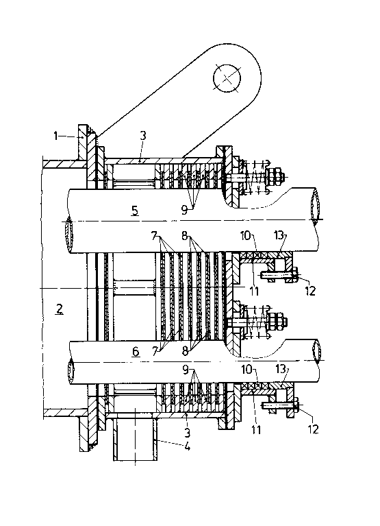

The present invention relates to apparatus for sealing retractable
soot-blower lances, at those locations where they pass through the wall of a
heat exchanger.
Each soot-blower lance has its own wallbox at such a seal against
pressure on the smoke-gas side of the heat exchanger. Such soot-blower lances
move either axially or in a helical path and labyrinth seals are usually
employed. For those soot-blowers which have solely a rotating movement, a
stuffing-box packing is used in place of a labyrinth seal.
It is an object of the present invention to configure a soot blower
seal such that one wall box can contain a plurality of soot-blower lances
which themselves can, in addition, be of different outside diameters.
In the seal herein described, lamellas are so arranged that a labyrinth
seal is produced and, simultaneously, each lance is allowed its own free play
movement. Soot-blower lances of various diameters, providing various cleaning
media, (air, stream, gas, water etc.) can thus be operated either
independently, or together.
More particularly, a sealing arrangement in accordance with the
invention comprises a labyrinth box having lamellas tightly surrounding the
soot-blower lances with predetermined play. The labyrinth box comprises a
wall box sealed tightly to a wall of the heat exchanger. The lamellas have
their outer edges secured in the wall box and tightly surro~nd alternate
lances with predetermined play so that each lance has enough room to move
freely whilst also being sealed off.
Embodiments of the invention will now be described with reference to
the accompanying drawing wherein the sole Figure is a longitudinal
cross-section through a wallbox with a seal embodying the present invention.
The wall 1 of a heat exchanger ~not shown), has a passage opening 2,
which is enclosed by a wallbox 3 secured to the wall 1. The wallbox 3 is
fitted with a connector 4 for compressed air which prevents smoke gas, usually
under pressure, from escaping from the heat exchanger.
A plurality of soot-blower lances, in this instance two, numbered 5 and
6 are housed within the wallbox 3 and operate using a gaseous cleaning agent
such as steam or air, or a liquid cleaning agent such as water. To clean the
tubes of the heat exchanger, the soot-blower lances 5, 6 are moved into the
heat exchanger through the passage opening 2, at which time they can move
PAT 11136-1

lX89587
axially or along a helical path. Once the blow~ng procedure has been
completed, the lances 5, 6 sre retracted into the wallbox 3. It is also
possible in some instances that one soot-blower lance can extend permanently
into the heat exchanger, and simply rotate when in operation. The two
soot-blowers 5, 6 -- which can be of different diameters -- are preferably
operated using different cleaning agents.
The lances 5, 6 are sealed by labyrinth seals, which consist of a
plurality of units comprising pairs of lamellas 7, 8 located at the outer
periphery by spacer rings 9, supported on the outer wall of the wallbox 3,
Lamellas 7, 8 are positioned very close to one another in each pair and each
respective lamella 7 or 8 is a tight fit around a respective one of the
soot-blower lances 5,6, and encloses the other respective soot-blower lance 5,
6 but with an amount of radial free play. Thus each respective soot-blower
lance 5, 6 has sufficient free play for movement, with respect to the other
blower, required for trouble-free operation, while being fully sealed by its
tight fitting respective lamella 7 or 8. This is achieved by the lamellas 7
and 8 being free to slide with respect to one another and within the spacer
rings 9.
In embodiments where more than two lances are included in a single wall
box, a respective lamella is provided in each unit of the labyrinth seal so
that each lance is tightly sealed by its respective lamella in each unit.
In addition, each of the soot-blower lances 5, 6 can be sealed at the
rear exit from the wallbox 3 by a stuffing-box seal. This consists of
stuffing-box packing 10 in contact with the respective lance 5,6, and enclosed
by the housing 11. The packing can be tightened down by way of a gland 13
using the screws 12.
PAT 11136-1
~ . - 2 -

Dessin représentatif
Une figure unique qui représente un dessin illustrant l'invention.
États administratifs

2024-08-01 : Dans le cadre de la transition vers les Brevets de nouvelle génération (BNG), la base de données sur les brevets canadiens (BDBC) contient désormais un Historique d'événement plus détaillé, qui reproduit le Journal des événements de notre nouvelle solution interne.

Veuillez noter que les événements débutant par « Inactive : » se réfèrent à des événements qui ne sont plus utilisés dans notre nouvelle solution interne.

Pour une meilleure compréhension de l'état de la demande ou brevet qui figure sur cette page, la rubrique Mise en garde , et les descriptions de Brevet , Historique d'événement , Taxes périodiques et Historique des paiements devraient être consultées.

Historique d'événement

Description Date
Inactive : CIB de MCD 2006-03-11
Inactive : Demande ad hoc documentée 1996-09-24
Le délai pour l'annulation est expiré 1996-03-24
Lettre envoyée 1995-09-25
Accordé par délivrance 1991-09-24

Historique d'abandonnement

Il n'y a pas d'historique d'abandonnement

Titulaires au dossier

Les titulaires actuels et antérieures au dossier sont affichés en ordre alphabétique.

Titulaires actuels au dossier
GERGEMANN GMBH
Titulaires antérieures au dossier
ALFONS TEMMINGHOFF
KARL ALBERS
Les propriétaires antérieurs qui ne figurent pas dans la liste des « Propriétaires au dossier » apparaîtront dans d'autres documents au dossier.
Documents

Pour visionner les fichiers sélectionnés, entrer le code reCAPTCHA :


Pour visualiser une image, cliquer sur un lien dans la colonne description du document (Temporairement non-disponible). Pour télécharger l'image (les images), cliquer l'une ou plusieurs cases à cocher dans la première colonne et ensuite cliquer sur le bouton "Télécharger sélection en format PDF (archive Zip)" ou le bouton "Télécharger sélection (en un fichier PDF fusionné)".

Liste des documents de brevet publiés et non publiés sur la BDBC .

Si vous avez des difficultés à accéder au contenu, veuillez communiquer avec le Centre de services à la clientèle au 1-866-997-1936, ou envoyer un courriel au Centre de service à la clientèle de l'OPIC.

({010=Tous les documents, 020=Au moment du dépôt, 030=Au moment de la mise à la disponibilité du public, 040=À la délivrance, 050=Examen, 060=Correspondance reçue, 070=Divers, 080=Correspondance envoyée, 090=Paiement})


Description du
Document 
Date
(aaaa-mm-jj) 
Nombre de pages   Taille de l'image (Ko) 
Revendications 1993-10-21 2 58
Abrégé 1993-10-21 1 10
Dessins 1993-10-21 1 26
Description 1993-10-21 2 72
Dessin représentatif 2001-07-18 1 28
Taxes 1994-08-24 1 50
Taxes 1993-08-10 1 60