Note : Les descriptions sont présentées dans la langue officielle dans laquelle elles ont été soumises.
~ACE-TYPE SHAFT SEAL WITH SHROUD
The present invention relates to an improved
shaft seal. More specifically, the present invention
relates to a shroud for a face seal having a resilient
bellows or diaphragm urging a rotating seal component
axially of a shaft against a stationary seal component,
particularly in a centrifugal pump adapted for pumping
liquids or slurries containing particulates.
A representative shaft seal used in
connection with a centrifugal pump is shown in Rockwood
et al. U.S. patent NO. 4,406,465, issued September 27,
1983. In such an application, it has been found to be
desirable to use a "face seal" which has a stationary
component with a flat, precisely machined, radial
surface and a rotating component having an abutting
flat radial surface similarly precisely machined. A
resilient member biases the rotating component against
the stationary component.
To assure a reliable leak-proof seal in a
variety of applications, the construction of face seals
has become increasingly complex, as illustrated by the
seal constructions shown in Van Vleet U.S. patent No.
3,188,095, issued June 8, 1965; Van Vleet U.S~ patent
No. 3,184,244, issued May 18, 1965; Azibert U.S. patent
No. 4,576,384, issued March 18, 1986; and Azibert et
al. U.S. patent No. 4,625,977, issued December 2, 1986
An economical alternative is a "welded metal
bellows seal" which has a set of stacked rings acting
similarly to a Belleville spring but with edges of
adjacent rings welded together. The stack of rings
form the resilient member for biasing the rotating seal
~X~0981
component axially of the shaft against the stationary
seal component. The "Type 680" seal available from
EG&G SE~LOL of Cranston, Rhode Island, is
representative of the bellows seal. Such seal works
quite well in some centrifugal pump applications. In
some applications, however, the liquid or slurry to be
pumped contains abrasive particulates. Vaughan V.S.
patent No. 3,774,323, issued November 27, 1973, for
example, shows a centrifugal pump used for dredging.
The dredged material may contain grit such as sand.
Similarly, Vaughan U.S. patent No. 3,973,866, issued
August 10, 1976, discloses a pump for slurries
containing solids which may include abrasive
particulates. For such applications, the gritty or
abrasive material can cause premature deterioration of
the exposed welds of the resilient bellows, destroying
the integrity of the economical welded metal bellows
seal.
The principal object of the present invention
is to provide an improvement for a conventional
bellows-type face seal allowing such seal to be used
reliably over an extended period in a centrifugal pump
when liquids or slurries containing abrasive
particulates are to be pumped, which improvement is of
inexpensive construction and easy to install and will
greatly increase the life of the seal assembly.
The foregoing objects can be accomplished by
providing in a liquid pump having a casing, a rotary
pumping member mounted for rotation in such casing, a
rotary drive shaft extending into the casing for
rotating the rotary pumping member, bearing means
mountiny the shaft and sealing means for preventing
1~909~31
access to the beariny means of the liquid being pumped
from the casing including a first seal component
encircling the drive shaft and mounted stationarily
relative to the casing, a second seal component
encircling and mounted for rotation with the drive
shaft and a genexally cylindrical liquid tight axially
resilient member encircling the drive shaft, extending
lengthwise therealong, having one end portion bearing
on the second seal component and biasing such second
seal component toward the first seal component to an
abutting sealing condition, the improvement comprising
a shroud attachment including a collar encircling and
fitted on the shaft adjacent to the end of the
resilient member remote from the sealing means, a
shroud portion extending from said collar lengthwise of
the drive shaft into overlapping relationship with the
second seal component and enclosing the resilient
member to shield the exterior of the resilient member
and a third seal component carried by said shroud in
slidable relationship axially of the shaft to the
second seal component.
Such objects also can be accomplished by
providing in a liquid pump having a casing, a rotary
pumping member mounted for rotation in such casing, a
rotary drive shaft extending into the casing for
rotating the rotary pumping member, bearing means
mounting the shaft and sealing means for preventing
access to the bearing means of the liquid being pumped
from the casing includiny a first seal component
encircling the drive shaft and mounted stationarily
relative to the casing, a second seal component
encircling and mounted for rotation with the drive
1~30~81
shaft and a generally cylindrical liquid tight axially
resilient metal bellows assembly encireling the drive
shaft, extending lengthwise therealong, having one end
portion carrying the second seal component, said one
end portion having an axial flange encircling the
second seal eomponent ancl said metal bellows biasing
such second seal component toward the first component
to an abutting sealing condition, the improvement
eomprising a shroud attaehment including a collar
encircling and fitted on the shaft adjacent to the end
of the resilient member remote from the sealing means,
a shroud portion extending from said collar lengthwise
of the drive shaft into overlapping relationship with
the seeond seal eomponent, having 2n inner, generally
eylindrical cavity with an inner wall portion extending
close alongside the resilient metal bellows for at
least substantially the full axial extent of the
resilient metal bellows to shield the exterior of the
resilient metal bellows and a third seal component
earried by said shroud in slidable relationship axially
of the shaft to the seeond seal component.
Such objects also can be aeeomplished by
providing in a liquid pump having a easing, a rotary
pumping member mounted for rotation in such casing, a
drive shaft extending into the casing for rotating the
rotary pumping member, bearing means mounting the shaft
and a seal for preventing aeeess of the liquid being
pumped from the easing to the bearing means ineluding a
first seal eomponent eneireling the drive shaft and
mounted substantially stationarily relative to the
easing, a seeond seal component eneireling and mounted
for rotation with the drive shaft and a generally
~9()~1
cylindrical liguid tight resilient member carrying the
second seal component, encircling the drive shaft,
mounted for rotation therewith and biasing the second
seal component toward the first seal component
generally axially of the drive shaft to an abutting
sealiny condition, the improvement comprising a shroud
elongated axially of the drive shaft and having an
inner, generally cylindrical cavity with an inner wall
portion extending close alongside the resilient member
for at least substantially the full axial extent of the
resilient member to limit exposure of the resilient
member to the liquid heing pumped, one end portion of
said shroud encircling the portion of the resilient
member axially remote from the first seal component and
the other end portion of said shroud encircling the
second seal component, means mounting said shroud for
rotation with the drive shaft and the resilient member,
and third resilient seal means for limiting flow of
liquid between said shroud and the second seal
component.
Such objects also can be accomplished by
providing in a liquid pump having a casing, a rotary
pumping member mounted for rotation in such casing, a
drive shaft extending into the casing for rotating the
rotary pumping me~ber, bearing means mounting the shaft
and a face seal for preventing access to the bearing
means of the liquid being pumped including a first seal
component encircling the drive shaft and mounted
stationarily relative to the casing, a second seal
component encircling and mounted for rotation with the
drive shaft and a generally cylindrical, li~uid tiyht,
axially resilient/ metal bellows assembly encircling
8:1;
the drive shaft, carrying the second seal component,
having an axial flange at one axial end portion
encircling the second seal component and biasing such
second seal component toward the first seal component
to an abutting sealing condition, the improvement
comprising an axially elongated rigid shroud attachment
including a collar encircling and clamped to the drive
shaft adjacent to the end portion of the bellows
assembly remote from the first seal component, an
intermediate portion having an inner, generally
cylindrical cavity encircling the metal bellows
assembly with an inner wall portion extending close
alongside the bellows assembly for at least
substantially the full axial extent of the bellows
assembly to shield the exterior of the bellows assembly
from the liquid being pumped, a free end portion
encircling the second seal component and the axial
flange of the metal bellows assembly and a third seal
component carried by said shroud in slidable relation-
ship axially of the shaft to the second seal component.
In drawings which illustrate the preferred
embodiments of the invention:
Figure 1 is a somewhat diagrammatic side
elevation of a centrifugal pump of the type with which
the shaft seal shroud in accordance with the present
invention can be used, with parts broken away;
Figure 2 is an enlarged, fragmentary,
longitudinal section through the pump of Figure 1, but
showing a conventional seal construction;
Figure 3 is a fragmentary longitudinal
section corresponding to Figure 2 but improved by
lX90981
addition of the shaft seal shroud in accordance withthe present invention; and
Figure 4 is a further enlarged fragmentary
longitudinal section through the shaft seal shroud in
accordance with the present invention, with parts
broken away.
Figure 1 illustrates the general environment
in which the shaft seal shroud in accordance with the
present invention is intended to be used. A
representative centrifugal pump 1 has a casing 2 with
axial inlet apertures 3 at the bottom. The upright
drive shaft 4 for the internal impeller 5 and external
booster propeller-chopper 6 is journaled in upper
bearings 7. Slurry or liquid containing grit or other
particulate matter is drawn upward through the inlet
apertures 3 and is discharged generally
circumferentially through the outlet pipe 8. The shaft
seal assembly 9 improved in accordance with the present
invention prevents the liquid being pumped from leaking
out the top of the casing alongside the drive shaft 4.
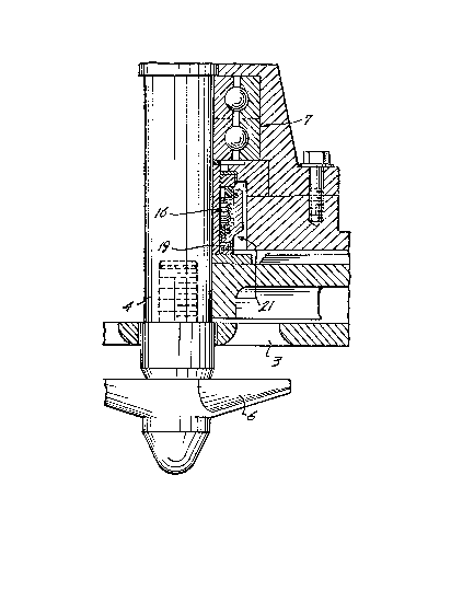
The conventional bellows seal construction is
illustrated in Figure 2. A bushing 10 is fixed to the
drive shaft 4 for axial positioning of the drive shaft
in the pump casing 2. A resilient O-ring 11 is
positioned between the top of bushing 10 and the bottom
of the rotating inner race 12 of the lower shaft
bearing 7.
The stationary seal ring component 13 is held
in the stationary seal yland assembly 14 which is
clamped to the pump casing 2. Such stationary
component 13 has a flat radial bottom surface.
~X~30981
The rotating seal ring component 15 is
carried by one end of a resilient, welded metal bellows
assembly 16 having inclined rings 17 welded together at
their inner and outer peripheral adjacent edges. The
other end portion of such bellows assembly is encircled
by a mounting ring 18 having setscrews 19 for clamping
the bellows assembly to the close-fitting bushing 10
encircling the drive shaft 4. A resilient O-ring 20 is
engaged between the inner surface of the bellows and
the shaft bushing slightly above the mountiny ring 18.
In the improved construction shown in Figures
3 and 4, the seal assembly is identical to that shown
in figure 2 with the exception that the mounting ring
18 of the Figure 2 seal is deleted and replaced with a
generally cylindrical shroud 1 in accordance with the
present invention. The bottom end portion of the
shroud forms a collar having an internal cylindrical
recess which fits closely over the bottom end portion
of the bellows assembly 16 and has threaded bores for
the setscrews 19 to clamp the shroud and the bellows
assembly to the shaft bushing 10 and shaft 4.
From its clamping bottom end portion, the
shroud is stepped outward to extend alongside
substantially the full axial length of the rotatiny
bellows assembly. Preferably there are resilient O-
rings 23 partially received in grooves 24 at opposite
sides of the welded bellows rings 17 to deter intrusion
of liquid to the inside of the shroud into engagement
with the bellows rings. nevertheless, such O-rings 23
need not assure a liquid tight seal in order that the
bellows rings be protected against the rapid
deterioration from abrasion which can occur in the
1'~90981
convention construction shown in Figure 2. In fact,
the fit of the O-rings 2~ against the bellows assembly
16 is sufficiently loose so as not to interfere with
axial extension and contraction of the bellows as
required to maintain the desired pressure of the
rotating seal ring component 15 against the stationary
seal ring component 13.
The effect of the shroud of the present
invention on the life of the seal assembly can be
dramatic. In one application where the liquid to be
pumped contained sand and possibly other abrasive
particulates, failure of the conventional seal
construction occurred in a matter of a few weeks as
compared to at least several months for the improved
construction. With reference to Figure 1, prior to
start up, slurry or liquid containing the gritty
material can pass through the inlet apertures 3,
between the outer edge of the impeller 5 and the inner
upright surface of the casing 2, along the top of the
impeller and into the casing recess in which the seal
assembly is mounted. In the conventional construction
shown in Figure 2, when the drive shaft 4 is rotated at
high speed rotating the bellows assembly 16 with it,
the slurry or liquid containing gritty material is
caught between the stationary casing 2 and the exposed
outer edge welds of the rings 17. Such welds are
prematurely worn by abrasive high speed contact with
the gritty material.
In the improved construction shown in Figures
1, 3 and 4, the bellows assembly is shielded by the
shroud 21 which also rotates with the drive shaft 4.
Even if liquid containing gritty material works its way
~909~3~
into the cavity between the shroud and the bellows
assembly, the contact of gritty material with the
bellows welds is not nearly so abrasive because such
trapped liquid is quickly induced to rotary movement
with the bellows and the shroud. At the exterior of
such cavity, the thick rigid shroud is not prone to
premature ~ailure by abrasion. As shown in Figures 3
and 4, the radial thickness of the shroud 21 is several
times as great as the radial thickness of the bellows
16.