Note : Les descriptions sont présentées dans la langue officielle dans laquelle elles ont été soumises.
1~9178~
Background of the Invention
~ he present invention relates generally to spray
nozzles and, more particularly, to spray nozzles which are
adapted for the application of liquids such as a~ricultural
chemicals.
Agricultural chemicals commonly are applied through
a multiplicity of spray nozzles which are supported on and
spaced along a common support boom. Particularly in recent
years, it has been found that such chèmicals can be
efficiently applied through air assisted nozzles such as that
shown in applicant's British Patent No. 2,157,591 of November
25, 1987 entitled "Air Assisted Nozzle With Deflector
Discharge Means". In such a nozzle, a pressurized air stream
is in~ected into the body of the nozzle to pre-atomize the
liguid before it i discharged from the ~pray tip of the
nozzie.
In some instances, however, it is preferred to apply
chemicals through non-air assisted nozzles (i.e.,
conventional hydraulic nozzles) in whlch the spray pattern is
formed as the pressurized liquid is discharged from the
nozzle tip. Because of the relatively large number of
individual spray nozzles which are mounted on a typical
agricultural spray boom, it can be time consuming to replace
air assisted nozzles with hydraulic nozzles or vice versa.
In addition, one wishing the option of both air assisted
application and conventional hydraulic application usually
must purchase a supply of both types of nozzles
q~
LCM:jj 1
~9178~
Summarv of the Invention
The general aim of the present invention is to
provide a new and improved spray nozzle which may be
used either as an air assisted nozzle or as a hydraulic
nozzle by making a relatively simple and easy
conversion to the nozzle.
A more detailed object of the invention is to
achieve the foregoing by providing a unique nozzle
having internal components which make the nozzle usable
as an air assi~ted nozzle but which may be easily
removed from the nozzle body to enable the n~zzle to be
used as a hydraulic nozzle.
Still another object is to provide a kit
comprising a relatively simple and inexpensive nozzle
body and comprising internal components adapted to be
inserted in~erchangeably into the body to enable the
same body to be used either as part of an air assisted
nozzle or as part o a hydraulic nozzle.
The invention also resides in the novel
construction of an insert which, when used in the
nozzle body, effects turbulent mixing of pressurized
air and liquid so as to produce good preatomization of
the liquid before the liquid is discharged from the
nozzle.
These and other objects and advantages of the
invention will become more apparent from the following
detailed description when taken in conjunction with the
accompanying drawings.
Brief Description of the Drawinqs
FIGURE 1 is a fragmentary end elevational view,
partially in cross-section, of a new and improved spray
nozzle incorporating the unique features of the present
~9178~
invention, the view being taken substantially along the
line 1-1 of FIG. 2.
FIG. 2 is a fragmentary cross-section taken
substantially along the line 2-2 of FIG. 1.
FIG. 3 is a fragmentary cross-section taken
substantially along the line 3-3 of FIG. 2 and shows
certain parts of the nozzle in moved positions.
FIG. 4 is a fragmentary cross-section taken
substantially along the line 4-4 of FIG. 2.
FIG. S is an exploded perspective view of certain
parts of the nozzle.
FIG. 6 is an exploded perspective view showing a
modified version of one of the nozzle parts.
FIG. 7 is a view similar to FIG. 2 but shows the
nozzle as having been converted from an air assisted
nozzle to a hydraulic nozzle.
While the invention is susceptible of various
modifications and alternative constructions, certain
preferred embodiments have been shown in the drawings
and will be described below in detail. It should be
understood, however, that there is no intention to
limit the invention to the specific forms described
but, on the contrary, the intention is to cover all
modifications, alternative constructions and
equivalents falling within the spirt and scope of the
invention.
Detailed Description of the Preferred Embodiments
For purposes of illustration, the invention is
shown in the drawings as embodied in a spray nozzle 10
which is adapted for use in spraying liquid and
particularly for spraying liquid fertili~er or
insecticide on an agricultural field. When used for
agricultural purposes, several nozzles are secured to
1~91~i
and are spaced along an elongated hollow boom (not
shown) which also serves as a manifold for delivering
liquid under high pressure to the nozzles. Reference
is made to Butterfield et al United States Patent
4,527,745 for an explanation as to how a nozzle of the
same general type as the present nozzle may be secured
to a boom or pipe and receive pressurized liquid
therefrom.
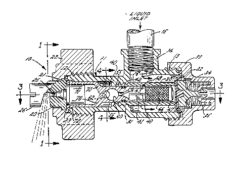
The nozzle 10 includes an elongated hollow body 11
molded of plastic and having opposite end hubs 12 and
13 which are externally threaded. An internally
threaded hub 14 is formed integrally with and projects
from one side of the body and receives a threaded pipe
15 which communicates with the boom to receive
pressurized liquid therefrom. The lower end of the hub
14 defines a circular inlet port 16 (FIG. 2) through
which liquid is introduced into the nozzle body 11.
As shown most clearly in FIG. 2, a discharge
nozzle tip 20 is located adjacent the end of the hub 12
of the body 11. To mount the tip, the latter is formed
with a radially extending peripheral flange 21 which is
clamped to the end of the hub 12 by a clamping nut or
cap 22 adapted to be ,thread'ed onto the hub. An annular
gasket 23 is interposed between the tip 21, the cap 22
and the end of the hub'12 in order to seal the
perimeter of the tip.
An axially extending discharge orifice 25 is
formed through the nozzle tip 20. Formed integrally
with the nozzle tip is a deflector flange 26 (FIG. 2)
whicn is disposed transversely to the line of travel of
the liquid flowing through the discharge orifice 25.
Such liquid forcefully strikes the deflector flange 26
and is broken down and atomized into particles of
relatively small size. In addition, the deflector
flange directs the particles into a well-defined flat
~L;2 917~
fan spray pattern transverse to the axis of the nozzle body
11. The construction, operation and advantages of the nozzle
tip 20 and the discharge flange 26 are disclosed in greater
detail in aforementioned British Patent No. 2,157,591.
Liquid which is admitted into the nozzle body 11 via
the inlet port 16 is shaped into a longitudinally flowing
stream by a cylindrical tube 30 (FIG. 2). The tube is
coaxial with and is spaced inwardly from the wall of the body
and its downstream end is threadably connected to the body at
31. As disclosed in commonly assigned Canadian Patent
Application Serial No. 526,336 of October 30, 1990, the tube
coacts with a resiliently flexible diaphragm 32 to form an
anti-drip valve which prevents liquid from dripping from the
nozzle tip 20 after the supply of pressurized liquid to the
inlet pipe 15 has been cut off. For this purpose, the
diaphragm is located adjacent the upstream end of the tube 30
and it~ peripheral margln i8 clamped between the end of the
hub 13 and a cap 33 which i5 threaded onto the hub. A valve
~ollower 34 iB supported slidably within the cap and is
operably connected to the diaphragm. Telescoped into the cap
is a coiled compression spring 35 which urges the diaphragm
toward a closed position against the upstream end of the tube
30 as shown in FIG. 2. When liquid u~der pressure is
delivered to the nozzle body 11 via the inlet pipe lS, the
pressurized liquid urges the diaphragm 32 away from the
upstream end of the tube as shown in FIG. 3 so as to enable
the liquid to flow through the tube and to be sprayed from
the nozzle tip 20. Upon cutting off of the liquid at the
pressure source, the spring 35 forces the diaphragm 32 into
sealing engagement with the upstream end of the tube 30 so as
to substantially prevent liquid from dripping out of the
nozzle tip.
LCM:jj 5
, :~
1;291t78~L
As described thus far, the nozzle 10 is basically
suitable for use as a hydraulic or non-air assisted nozzle in
the same general manner as the nozzle disclosed in the
aforementioned Canadian Application Serial No. 526,336. In a
pure hydraulic nozzle (i.e., a non-air assisted nozzle), the
pressurized liquid is delivered through the nozzle at a
relatively high flow rate and is broken up into relatively
large particles upon being sprayed from the nozzle tip 20.
Hydraulic nozzles are generally preferred for use under
conditions where it is desired to spray a field with
relatively large quantities of a liquid chemical solution
having a high percentage of water.
For other agricultural applications, air assisted
nozzles are preferred over pure hydraulic nozzles. In
general terms, an air assisted nozzle is a nozzle in which
the liguid flows through the nozzle at a comparatively slow
flow rate and in which a pressurized stream of air is
injected into the nozzle in order to preliminarily beak up or
atomize the li~uid prior to the liguid being spxayed ~rom the
nozzle tip. ~ir assisted nozzles are generally used in
situations where a comparatively small quantity of a more
highly concentrated chemical solution is to be sprayed on a
~ield of given area.
In accordance with the present invention, the nozzle
10 is provided with a unique insert member 40 (FIGS. 2 and 5)
which may be placed in the nozzle to enable the nozzle to
operate in an air assisted mode and which may be removed
easily from the nozzle to convert the nozzle for use in a
hydraulic mode. As will become apparent, the insert 40
permits the nozzle 10 to be easily changed over from air
assisted to hydraulic, or vice versa, without need o~
maintaining a supply of each type of nozzle and without need
of
LCM:jj 6
,
8~
removing one type of nozzle from the boom and
installing the other type of nozzle on the boom each
time a conversion is made.
More specifically, the insert 40 includes a
tubular orifice member 41 (FIGS. 2 and 5) made of brass
or the like. The orifice member is cylindrical and is
telescoped into the downstream end of the tube 30 with
a tight but sliding fit. An O-ring 42 (FIG. 2) fits
within a groove 43 (FIG. 5) around the outer periphery
of the orifice member 41 and is compressed against the
inner wall of the tube 30 to establish a seal between
the orifice member and the tube.
Formed through the downstream end portion of the
orifice member 41 is a flow restricting orifice 45
which serves to reduce the flow rate of liquid flowing
from the tube 30 toward the nozzle tip 20. In this
particular instance, the orifice includes a
frustoconical upstream portion whose small diameter end
joins a cylindrical downstream portion
Dlrt and other foreign particles are ~iltered from
the liquid before the liquid flows through the orifice
45. For this purpose, a tubular screen-like strainer
46 extends from the upstream end of the orifice member
41 and is spaced radially inwardly from the wall of the
tube 30 so that liquid entering the tube must pass
radially through the strainer before flowing to the
orifice 45. One end of the strainer 46 abuts the
upstream end of the orifice member 41 while the other
end of the strainer abuts and is closed off by the head
47 (FIG. 5) of a pin 48. The latter is telescoped
slidably into both the strainer and the upstream end of
the orifice member. In the embodiment shown in FIGS. 1
to 5, the pin is of cruciform cross-section and is
formed with four angularly spaced fins 49 (FIG. 5)
which define flow passages permitting liquid to flow
. .
~L~.9178~
through the strainer and into the orifice member. When
the insert 40 is removed from the nozzle body 11, the
pin 48 may be pulled out of the orifice member 4i and
then the strainer 46 may be pulled off of the pin to
permit cleaning or replacement of the strainer.
A modified pin 48 for supporting the strainer 46
is shown in FIG. 6. In this instance, the pin is
hollow and generally cylindrical and is formed with
four angularly spaced and longitudinally extending
slots 49' which permit liquid to flow into the pin and
then to the orifice member 41. Two axially spaced
rings 50 extend circumferentially around the pin 48 and
hold the strainer in radially outwardly spaced relation
with the body of th~ pin.
In carrying out the invention, the insert 40
includes an elongated impingement element 55 (FIG. 5)
for breaking up the stream of liquid flowing through
the orifice 45 and for causing the liquid to mix with a
pressurlzed air stream which also is broken up by the
impingement element. Herein, the impingement element
55 is in the form of an elongated and flat bar formed
integrally with the downstream end of the orifice
member 41, the bar being of rectangular cross-
section. The bar 55 extends longitudinally into an
axially elongated mixing chamber 56 of circular cross-
section defined within the nozzle body 11. As shown in
FIGS. 2 and 3, the rectangular bar 55 is spaced
inwardly from the circular wall of the chamber around
the entire periphery of the bar.
A transversely extending circular hole 60 is
formed through the bar 55 immediately downstream o~ the
orifice 45. The hole 60 communicates with the orifice
45 and, as pressurized liquid is discharged from the
orifice, it strikes the downstream wall of the hole.
The downstream wall thus defines an impingement surface
1;?.9~781
which deflects the liquid transversely to break up the
liquid and cause the liquid to flow through the chamber
56 along the sides of the bar 55.
As the liquid flows through the chamber 56, it is
preliminarily broken up by a pressurized stream of air
which is admitted into the chamber 56 through a
circular air inlet port 62 (FIG. 3) formed in the
nozzle body 11 and extending transversely to the
chamber and the stream of liquid flowing through the
cham~er. The inlet port 62 is located at the inner end
of a fitting 63 (FIGS. 1 and 3) joined to the nozzle
body 11 and connected to a flexible tube 64 which
communicates with a supply of pressurized air by way of
a shut of f valve 65. When the valve is opened, a
stream of pressurized air is injected transversely into
the chamber 56.
As shown in FIGS. 2 and 3, the axis of the air
inlet port 62 extends parallel to the axis of the hole
60 in the bar 55 but the port 62 is smaller in diameter
than the hole 60 and its axis is offset in a downstream
direction from the ~xis of the hole. As a resu~t, only
about one-half of the area of the air inlet port 62 is
in registry with the hole 60 while the downstream half
of the air inlet port is located in opposing relation
with a side surface aréa 66 (FIG. 4) of the bar 5S. By
virtue of this arrangement, the surface 66 defines an
impingement surface which deflects and breaks up the
air stream. Considerable turbulence for preatomizing
the liquid stream is created by the air stream being
broken up by the impingement surface 66, by the liquid
stream being broken up by the wall o the hole 60 and
as a result of the air stream being injected
transversely into the longitudinally flowing liquid
stream. The liquid thus flows toward the nozzle tip 20
in the form of finely divided particles.
~91781
The insert 40 is completed by two radiall~ spaced
webs 70 (FIG. 5) formed integrally with and extending
axially from the bar 55 and having downstream ends
joined to a cylindrical sleeve 71. Formed on the
downstream end of the sleeve is an outwardly radially
extending flange 72 which is adapted to be clamped by
the cap 22 between the sealing gasket 23 and an
internal shoulder at the downstream end portion of the
nozzle body 11. An axially extending key 73 (FIG. 5)
at the upstream side of the flange 72 fits into a
keyway in the nozzle body 11 so as to orient the insert
40 angularly in the body in such a manner that the axis
of the hole 60 extends parallel to the axis of the air
inlet port 62.
Uhen the insert 40 is in place in the nozzle body
11, the flow rate of the liquid stream is reduced by
the orifice 45 and, in addition, the stream is
preliminarily atomized by the coaction of the wall of
the hole 60, the impingement surace 66 of the bar 55
and the mutually tran~verse flow relation between the
liquid stream and the air stream. The insert 40 may be
removed from the body 11 simply by unscrewing the cap
22 and taking the cap, the nozzle tip 20 and the
sealing gasket 23 off of the body as a unit.
Thereafter, the insert with the attached pin 48 and
strainer 46 may be pulled axially out of the downstream
end of the body 11.
When the insert 40 is out of the body 11, the
nozzle 10 may be converted for use in a hydraulic mode
simply by placing a tubular strainer 80 in the chamber
56 as shown in FIG. 7. The strainer 80 is telescoped
over a pin 81 which may be similar to the pins 48 or
48' and which is formed with a radially extending
flange 83 at its downstream end. The flange 83 is
adapted to be clamped against the internal shoulder in
.,
~;~91'781
the body 11 by the gasket 23 when the cap 22 and the
nozzle tip 20 are screwed back on to the body. To
facilitate even faster assembly and disassembly of the
cap 22, the latter may be of the quick disconnect
bayonet type such as disclosed in Butterfield et al
United States Patent 4,527,745. The strainer 80 also
may be similar to the strainer disclosed in such
patent.
When the nozzle 10 is set up as shown in FIG. 7
for use in the hydraulic mode, the air fitting 63 is
closed o~f to prevent liquid from escaping through the
fitting. This may be accomplished either by shutting
off the valve 65, by pinching the tube 64 closed with a
clamp or by disconnecting the tube from the fitting 63
and inserting a plug into the fitting.
From the foregoing, it will be apparent that the
present invention brings to the art a new and improved
nozzle 10 which may be quickly and easily converted
between an air assisted, relatively low flow rate mode
and a non-air assisted, comparatively h~gh flow rate
mode. When set up in the air assisted mode, the nozzle
e~fects very good preliminary atomization of the liquid
as a result of the interaction of the insert 40 with
the air and liquid streams.
.... . . . .