Sélection de la langue

Search

Sommaire du brevet 1291798 

Énoncé de désistement de responsabilité concernant l'information provenant de tiers

Une partie des informations de ce site Web a été fournie par des sources externes. Le gouvernement du Canada n'assume aucune responsabilité concernant la précision, l'actualité ou la fiabilité des informations fournies par les sources externes. Les utilisateurs qui désirent employer cette information devraient consulter directement la source des informations. Le contenu fourni par les sources externes n'est pas assujetti aux exigences sur les langues officielles, la protection des renseignements personnels et l'accessibilité.

Disponibilité de l'Abrégé et des Revendications

L'apparition de différences dans le texte et l'image des Revendications et de l'Abrégé dépend du moment auquel le document est publié. Les textes des Revendications et de l'Abrégé sont affichés :

  • lorsque la demande peut être examinée par le public;
  • lorsque le brevet est émis (délivrance).
(12) Brevet: (11) CA 1291798
(21) Numéro de la demande: 1291798
(54) Titre français: MODULATEUR D'IMPULSIONS EN DUREE
(54) Titre anglais: PULSE-WIDTH MODULATOR
Statut: Périmé et au-delà du délai pour l’annulation
Données bibliographiques
(51) Classification internationale des brevets (CIB):
  • H03K 7/08 (2006.01)
(72) Inventeurs :
  • RIEDGER, THOMAS (Allemagne)
(73) Titulaires :
  • LUCENT TECHNOLOGIES INC.
(71) Demandeurs :
  • LUCENT TECHNOLOGIES INC. (Etats-Unis d'Amérique)
(74) Agent: KIRBY EADES GALE BAKER
(74) Co-agent:
(45) Délivré: 1991-11-05
(22) Date de dépôt: 1987-06-04
Licence disponible: S.O.
Cédé au domaine public: S.O.
(25) Langue des documents déposés: Anglais

Traité de coopération en matière de brevets (PCT): Non

(30) Données de priorité de la demande:
Numéro de la demande Pays / territoire Date
P 3619353.4 (Allemagne) 1986-06-09

Abrégés

Abrégé anglais


ABSTRACT:
The pulse-width modulator described herein comprises a
square-wave generator, a retriggerable monostable multivibrator, a
gate circuit and a controllable current source, having a capacitor
as a timing element for the multivibrator. If the modulator is
assembled from standard building blocks in CMOS-technology and
several external components, its power dissipation will remain
below 10 mW. If completed by a variable-gain amplifier - likewise
carried out in CMOS-technology - and a reference voltage source,
the pulse width modulator can be advantageously used in the
control circuit of a clocked direct voltage converter. Then the
internal losses of a direct voltage converter constructed thus
will still remain below 25 mW.

Revendications

Note : Les revendications sont présentées dans la langue officielle dans laquelle elles ont été soumises.


6 20104-8320
THE EMBODIMENTS OF THE INVENTION IN WHICH AN EXCLUSIVE
PROPERTY OR PRIVILEGE IS CLAIMED ARE DEFINED AS FOLLOWS:
1. A pulse-width modulator, wherein through a gate circuit
a square-wave oscillation having a fixed duty cycle and a fixed
frequency is pulse-width modulated in proportion to the value of
an input signal, characterized in that a retriggerable monostable
multivibrator is provided, whose timing element comprises a
capacitor charged by a current source controlled by the input
signal, in that the output signal of a square-wave generator is
applied to the trigger input of the multivibrator and to an input
of the gate circuit and in that the output signal of the
multivibrator is applied to the other input of the gate circuit.
2. A pulse-width modulator as claimed in claim 1,
characterized in that the monostable multivibrator is triggered by
the falling edges of the square-wave oscillation and in that the
gate is an AND-gate.
3. A pulse-width modulator as claimed in claim 1 or 2,
characterized in that the controllable current source is a PNP-
transistor with emitter resistance, the collector of the
transistor being connected to a terminal of the capacitor and the
base of the transistor being triggered by the input signal.
4. A pulse-width modulator as claimed in claim 1 or 2,
characterized in that the input signal is the setting quantity
supplied by variable-gain amplifier, the input voltage of the

7 20104-8320
variable-gain amplifier being the controlling variable and the
other input voltage being the reference voltage produced by a
reference voltage source.
5. A pulse-width modulator as claimed in claim 3,
characterized in that the input signal is the setting quantity
supplied by variable-gain amplifier, the input voltage of the
variable-gain amplifier being the controlling variable and the
other input voltage being the reference voltage produced by a
reference voltage source.
6. A pulse-width modulator as claimed in claim 4,
characterized in that the variable-gain amplifier, the reference
voltage source, the square-wave generator, the gate circuit, the
monostable multivibrator and the controllable current source are
monolithically integrated.
7. A pulse-width modulator as claimed in claim 5,
characterized in that the variable-gain amplifier, the reference
voltage source, the square-wave generator, the gate circuit, the
monostable multivibrator and the controllable current source are
monolithically integrated.
8. A pulse-width modulator as claimed in claim 4,
characterized in that the monostable multivibrator, the square-
wave generator, the gate circuit and the variable-gain amplifier
are implemented in CMOS-technology.

8 20104-8320
9. A pulse-width modulator as claimed in claim 5,
characterized in that the monostable multivibrator, the square-
wave generator, the gate circuit and the variable-gain amplifier
are implemented in CMOS-technology.
10. A pulse-width modulator as claimed in any one of claims
1, 2, 5, 6, 7, 8 or 9, characterized in that the frequency of the
square-wave generator is slightly above the hearing threshold.
11. A pulse-width modulator as claimed in claim 3,
characterized in that the frequency of the square-wave generator
is slightly above the hearing threshold.
12. A pulse-width modulator as claimed in claim 4,
characterized in that the frequency of the square-wave generator
is slightly above the hearing threshold.

Description

Note : Les descriptions sont présentées dans la langue officielle dans laquelle elles ont été soumises.

~91798
PHD 86311 1 1.3.1987
Pulse-width modulator.
The invention relates to a pulse-width modulator
wherein through a gate circuit a square-wave oscillation
having a fixed duty cycle and a fixed frequencyis pulse-
width modulated in proportion to the value of an input
signal.
Pulse-width modulators are, for e~ample, used
in clocked and controlled direct voltage converters,
therein converting an analog voltage available as a
setting quantity into a square-wave ~ignal having a
variable duty cycle. With the pulse-width modulated
cignal the switching transistor of the converter i6 opened
or closed depénding on the length of the pulses.
The ~erman Patent DE-PS 32 27 296 discloses a
pulse-width modulator compri~ing a sawtooth oscillator,
two comparators~ an AND-gate and amplifiers, One comparator
compare~ the analog input signal to the sawtooth voltage
and the other comparator compares the sawtooth voltage to
a time-constant voltage. The time-constant voltage i8
derived from the supply voltage by a voltage divider. The
output voltages of the comparators are applied to the
inputs of the AND-gate, whose output signal represents
the pulse-width modulated signal. The duty cycle of the
output signal varies between a maximum value to be
adjusted by the voltage divider and zero value, always
according to the amplitude of the continuous input ~ignal.
As the known pulse-width modulator requires two
oomparators having short-process delay times and a saw-
tooth generator having a linear ramp voltage and as thece
building blocks consist of bipolar transi~tors~ it will
have a relatively large power dis~ipation, ~herefore~
it is~ for example~ unsuitable for use in clocked direct
voltage converters having a switching rate of approxima-
tely 20 kHz~ if extremely low internal los~e~ are

~.sl7sa
PHD 86311 2 1.3.1987
additionall~ required.
The invention has for its object to provide a
pulse-width modulator as defined in the opening paragraph
which can be realized with fast and extremely low-loss
building blocks.
The object is accomplished in that a retriggera-
ble monostable multivibrator is provided, whose timing
element comprises a capacitor charged by a current source
controlled by the input signal, in that the output signal
Of a square-wave generator is applied to the trigger
input of the multivibrator and to an input of the gate
circuit and in that the output signal of the multivibrator
is applied to the other input of the gate circuit.
The monostable multivibrator, the square-wave
generator and the AND-gate mentioned hereinbefore are
obtainable as standard CMOS building blocks; they i.a.
guarantee the extremely low internal lo~ses. ~or all
building blocks together these losses will remain less
than 10 mW.
Advantageous features of the invention are
indicatad in the subcl~ms. An embodiment of the invention
is e~plained and described in further detail with reference
to the drawings in which:
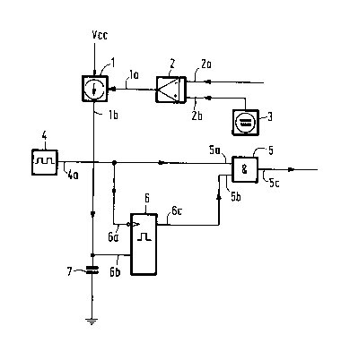
Fig. 1 shows a circuit having ~eatures in
accordance with the invention and
Fig. 2 shows pulse diagrams to elucidate its
mode of operation.
The principal componants of the circuit in
accordance with Figure 1 are a controllable current
source 1, a square-wave generator 4~ an AND_gate 5, a
monostable edge-triggered multivibrator 6 and a capacitor
7. The following building blocks are used: the CMOS-timer
7555 as the square-wave generator 4, the CMOS-multivibrator
MC 14528 B as the monostable multivibrator 6~ a bipolar
transistor with an emitter resistance (Tietze, U. ;
Schenk, Ch.: Halbleiter-Schaltungstechnik, 5. Auflage~
Springer Verlag Berlin, Heidelberg~ New York 1980) as the

~,91798
PHD 86311 3 1.3.1987
controllable current source and the CMOS-building block
MC 14O11 B as the AND-gate.
The capacitor 7, one electrode of which is
connected to the output 1b of the current source 1, is
charged via the controllable current source 1. The other
electrode of capacitor 7 is connected to the reference
potential. The capacitor 7 and the con-trollable current
source 1 constitute the timing element for the monostable
multivibrator 6. If the capacitor voltage exceeds half
the operating voltage VCC/2, the level at the output 6c
of the multivibrator 6 will change from HIGH to LOW. As
the output 4a of the square-wave generator 4 is connected
to the trigger input 6a of the monostable multivibrator 6,
the capacitor 7 is discharged with evePy falling (nega-
tive) slope of the square-wave oscillation.
If the charging current I is sufficiently small,
the voltage at capacitor 7 will not reach half the
operatin~ volta~e VCC/2 during the period ~etween two
discharges and the level at the output 6c will remain HIGH.
The HIGH level at the output 6c - owing to
output 6c being connected to input 5b of AND-gate 5 -
causes the AND-gate 5 to open for the complete pulses of
the square-wave generator 4 which are applied to an input
5a of the AND-gate 5. Consequently, ato~tput 5c a
square-wave oscillation will occur having the same duty
cycle as the oscillation of the square-wave generator 4;
in both cases the duty cycle of the oscillation is O.5.
If the charging current I for the capacitor 7
is larger, the capacitor voltage between two discharges
will exceed half the value of the operating voltage.
Consequently, the level at output 6c of the monostable
multivibrator 6 will change to LOW and the pulses of the
square-wave generator will be present in a narrower shape
at the output 5c of AND-gate 5~ thus reducing the duty
cycle, With the maximum charging current I there are no
pulses present at output 5c.

~91798
PHD 86311 4 1.3.1987
The pulse diagrams of Figure 2 show the
described cycles in more detail. The amplitudes of
the binary signals are represented by their levels H
(HIGH) and L (LOW). The reference character of the
output where the signal occurs is shown on the left of
each diagram. Thus the top diagram shows the pulse
sequence at output 4a of the square-wave generator 4.
The next diagram shows a possible variation of the output
current I of the controllable current source 1. Starting
from a maximum value the current I continuousl~
decreases. The third diagram from the top shows how the
signal at output 6c changes as a function of the current
I; d symbolizes the charging time of the capacitor 7
until half the operating voltage is reached. The bottom
diagram shows the associated signal at output 5c and AND-
gate 5. The change of the duty cycle from O for largecharging currentR I to O.5 for small charging currents is
very distinct.
A variable-gain amplifier 2 and a reference
voltage source 3 in Figure 1 suggest an advantageous use
of the thusfar described pulse~idth modulator, namely its
insertion in the control system of a pulsed direct
voltage converter. The outpùt voltage of the variable-
gain amplifier 2 controls the controllable current
sour¢e 1. The controlled variable - in this case the
output voltage of the converter or a voltage proportional
thereto- is applied to input 2a of the variable-gain
amplifier 2 and the output voltage of the reference
voltage-source 3 is applied to input 2b.
The variable-gain amplifier 2 is likewise
obt~inable in CMOS technology, for example, as a low-
power CMOS operational amplifier 7611, so that the entire
circuit according to Figure 1 - although the reference
voltage source 3 cannot be manufactured in CMOS technology
- has a power dissipation which is still below 10 mW. In
addition, the circuit is integrable and even such that
CMOS-building blocks and bipolar building blocks are
accommodated on one chip.

~917~
PHD 86311 5 1.3.1987
To reduce the power dissipation still the
further frequency of the square-wave generator is lowered
such that it is just above the threshold of hearing, for
example at 18 kHz. This will reduce the switching
operations per time unit for all relevant bu~ding blocks
and hence also the dissipation linked with the switching
operations. The internal losses of a direct voltage
converter can be reduced to below 25 mW when using a
control circuit in accordance with Figure 1.

Dessin représentatif
Une figure unique qui représente un dessin illustrant l'invention.
États administratifs

2024-08-01 : Dans le cadre de la transition vers les Brevets de nouvelle génération (BNG), la base de données sur les brevets canadiens (BDBC) contient désormais un Historique d'événement plus détaillé, qui reproduit le Journal des événements de notre nouvelle solution interne.

Veuillez noter que les événements débutant par « Inactive : » se réfèrent à des événements qui ne sont plus utilisés dans notre nouvelle solution interne.

Pour une meilleure compréhension de l'état de la demande ou brevet qui figure sur cette page, la rubrique Mise en garde , et les descriptions de Brevet , Historique d'événement , Taxes périodiques et Historique des paiements devraient être consultées.

Historique d'événement

Description Date
Lettre envoyée 2005-01-04
Le délai pour l'annulation est expiré 2004-11-05
Inactive : Renversement de l'état sera réputé périmé 2004-01-27
Lettre envoyée 2003-11-05
Inactive : Lettre officielle 1997-10-17
Inactive : Transferts multiples 1997-09-26
Accordé par délivrance 1991-11-05

Historique d'abandonnement

Il n'y a pas d'historique d'abandonnement

Historique des taxes

Type de taxes Anniversaire Échéance Date payée
TM (catégorie 1, 6e anniv.) - générale 1997-11-05 1997-09-30
TM (catégorie 1, 7e anniv.) - générale 1998-11-05 1998-09-24
TM (catégorie 1, 8e anniv.) - générale 1999-11-05 1999-09-20
TM (catégorie 1, 9e anniv.) - générale 2000-11-06 2000-09-15
TM (catégorie 1, 10e anniv.) - générale 2001-11-05 2001-09-20
TM (catégorie 1, 11e anniv.) - générale 2002-11-05 2002-09-19
Titulaires au dossier

Les titulaires actuels et antérieures au dossier sont affichés en ordre alphabétique.

Titulaires actuels au dossier
LUCENT TECHNOLOGIES INC.
Titulaires antérieures au dossier
THOMAS RIEDGER
Les propriétaires antérieurs qui ne figurent pas dans la liste des « Propriétaires au dossier » apparaîtront dans d'autres documents au dossier.
Documents

Pour visionner les fichiers sélectionnés, entrer le code reCAPTCHA :


Pour visualiser une image, cliquer sur un lien dans la colonne description du document. Pour télécharger l'image (les images), cliquer l'une ou plusieurs cases à cocher dans la première colonne et ensuite cliquer sur le bouton "Télécharger sélection en format PDF (archive Zip)" ou le bouton "Télécharger sélection (en un fichier PDF fusionné)".

Liste des documents de brevet publiés et non publiés sur la BDBC .

Si vous avez des difficultés à accéder au contenu, veuillez communiquer avec le Centre de services à la clientèle au 1-866-997-1936, ou envoyer un courriel au Centre de service à la clientèle de l'OPIC.


Description du
Document 
Date
(aaaa-mm-jj) 
Nombre de pages   Taille de l'image (Ko) 
Page couverture 1993-10-23 1 12
Revendications 1993-10-23 3 77
Abrégé 1993-10-23 1 19
Dessins 1993-10-23 1 14
Description 1993-10-23 5 183
Dessin représentatif 2000-07-12 1 5
Avis concernant la taxe de maintien 2004-01-27 1 175
Avis concernant la taxe de maintien 2005-01-04 1 173
Correspondance 1997-10-17 1 15
Correspondance 1997-10-17 3 39
Taxes 1996-09-17 1 79
Taxes 1995-09-22 1 74
Taxes 1994-09-09 1 73
Taxes 1993-09-21 1 57